Service MITSUBISHI L200 2018 (in English) Owners Manual
[x] Cancel search | Manufacturer: MITSUBISHI, Model Year: 2018, Model line: L200, Model: MITSUBISHI L200 2018Pages: 466, PDF Size: 28.42 MB
Page 353 of 466
CAUTIONlBe careful that hands or fingers are not trap-
ped when closing the bonnet.
l Before driving, make sure that the bonnet is
securely locked. An incompletely locked bonnet can suddenly open while driving.
This can be extremely dangerous.NOTEl If this does not close the bonnet, release it
from a slightly higher position.
l Do not press down firmly on the bonnet as
doing so could damage it.Engine oil
E01000404693
To check and refill engine oil
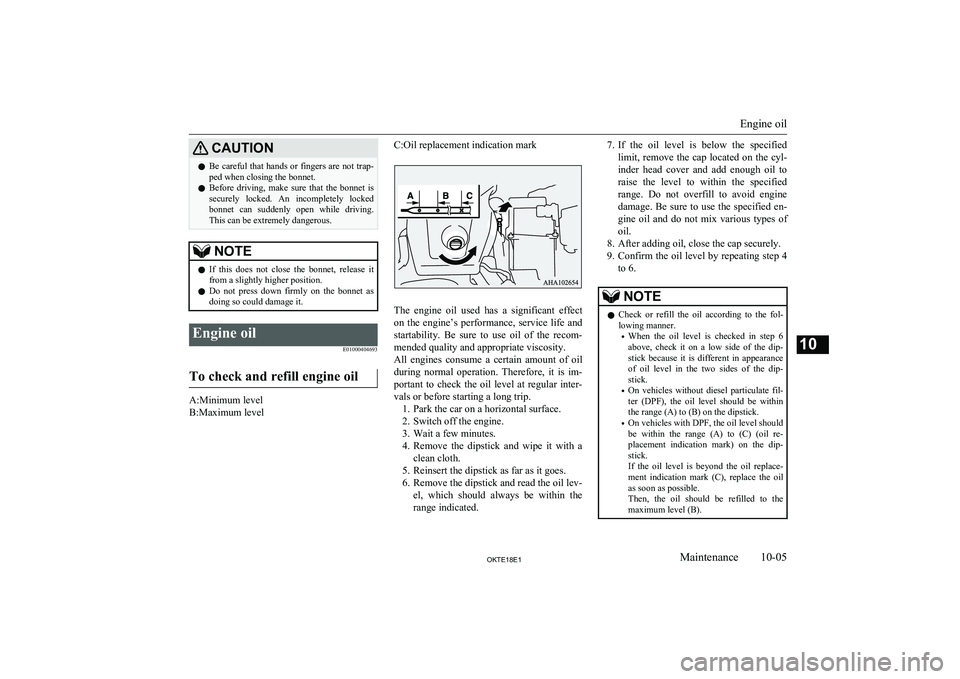
A:Minimum level
B:Maximum level
C:Oil replacement indication mark
The engine oil used has a significant effect on the engine’s performance, service life and
startability. Be sure to use oil of the recom- mended quality and appropriate viscosity.
All engines consume a certain amount of oil during normal operation. Therefore, it is im-portant to check the oil level at regular inter-
vals or before starting a long trip. 1. Park the car on a horizontal surface.
2. Switch off the engine.
3. Wait a few minutes.
4. Remove the dipstick and wipe it with a
clean cloth.
5. Reinsert the dipstick as far as it goes.
6. Remove the dipstick and read the oil lev- el, which should always be within therange indicated.
7. If the oil level is below the specified
limit, remove the cap located on the cyl- inder head cover and add enough oil to
raise the level to within the specified
range. Do not overfill to avoid engine damage. Be sure to use the specified en-
gine oil and do not mix various types of
oil.
8. After adding oil, close the cap securely.
9. Confirm the oil level by repeating step 4
to 6.NOTEl Check or refill the oil according to the fol-
lowing manner.
• When the oil level is checked in step 6
above, check it on a low side of the dip-
stick because it is different in appearance
of oil level in the two sides of the dip-
stick.
• On vehicles without diesel particulate fil-
ter (DPF), the oil level should be within the range (A) to (B) on the dipstick.
• On vehicles with DPF, the oil level should
be within the range (A) to (C) (oil re-
placement indication mark) on the dip-
stick.
If the oil level is beyond the oil replace-
ment indication mark (C), replace the oil as soon as possible.
Then, the oil should be refilled to the maximum level (B).
Engine oil
10-05OKTE18E1Maintenance10
Page 354 of 466
NOTE•On vehicles with DPF, the engine oil will
increase due to a little fuel getting mixed
in the engine oil when the DPF regener- ates to burn away the PM (particulate
matter). However, it does not indicate a
malfunction.
• The engine oil level will be increased due
to an amount of the fuel being mixed in
the engine oil when the DPF regenerates
to burn away the PM (particulate matter). It does not indicate a malfunction.
In the following conditions, the engine oil level may increase easily. We recommendyou to have it checked frequently.
•frequent driving at uphill and down-
hill
• frequent driving at high altitudes
• frequent and extended idling
• frequent driving through a traffic
jam
l The engine oil will deteriorate rapidly if the
vehicle is subjected to severe conditions, re- quiring earlier oil replacement. Please refer
to the maintenance schedule.
l For handling of used engine oils, refer to
page 2-06.Selection of engine oil
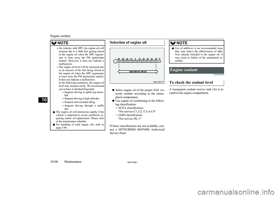
l Select engine oil of the proper SAE vis-
cosity number according to the atmos-pheric temperature.
l Use engine oil conforming to the follow-
ing classification: • ACEA classification: “For service C1, C2, C3 or C4”
• JASO classification: “For service DL-1”
If those classifications are not available, con- tact a MITSUBISHI MOTORS Authorized
Service Point.
NOTEl Use of additives is not recommended since
they may reduce the effectiveness of addi-
tives already included in the engine oil. It may result in failure of the mechanical as-
sembly.Engine coolant
E01000503509
To check the coolant level
A transparent coolant reserve tank (A) is lo-cated in the engine compartment.
Engine coolant
10-06OKTE18E1Maintenance10
Page 357 of 466
CAUTIONlUse only the specified brake fluid.
Do not mix or add different brands of brake fluid to prevent chemical reactions.
Do not let any petroleum-based fluid touch, mix with, or get into the brake fluid.
This will damage the seals.
l Keep the reservoir tank cap closed to pre-
vent the brake fluid from deteriorating ex- cept maintenance.
l Clean the filler cap before removing and
close the cap securely after maintenance.Clutch fluid*
E01001001581
To check the fluid level
The clutch fluid in the master cylinder should
be checked when performing other under- hood service. In addition, the system shouldbe checked for leakage at the same time.
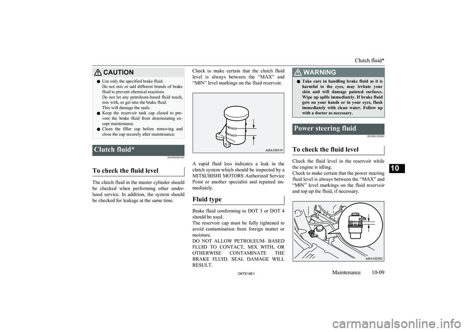
Check to make certain that the clutch fluid
level is always between the “MAX” and
“MIN” level markings on the fluid reservoir.
A rapid fluid loss indicates a leak in the
clutch system which should be inspected by a
MITSUBISHI MOTORS Authorized Service
Point or another specialist and repaired im- mediately.
Fluid type
Brake fluid conforming to DOT 3 or DOT 4 should be used.
The reservoir cap must be fully tightened to avoid contamination from foreign matter or
moisture.
DO NOT ALLOW PETROLEUM- BASED FLUID TO CONTACT, MIX WITH, OR
OTHERWISE CONTAMINATE THE BRAKE FLUID. SEAL DAMAGE WILLRESULT.
WARNINGl Take care in handling brake fluid as it is
harmful to the eyes, may irritate your
skin and will damage painted surfaces. Wipe up spills immediately. If brake fluid
gets on your hands or in your eyes, flush immediately with clean water. Follow up
with a doctor as necessary.Power steering fluid
E01001102491
To check the fluid level
Check the fluid level in the reservoir whilethe engine is idling.
Check to make certain that the power steering
fluid level is always between the “MAX” and
“MIN” level markings on the fluid reservoir
and top up the fluid, if necessary.
Clutch fluid*
10-09OKTE18E1Maintenance10
Page 363 of 466
On 4WD vehicles in which the driving poweris distributed preferentially to the rear
wheels, ensure that the snow traction device (Tyre chains) are fitted on the rear.
Use only snow traction device (Tyre chains)
which are designed for use with the tyres mounted on the vehicle: use of the incorrect size or type of snow traction device (Tyre
chains) could result in damage to the vehicle
body.
Contact a MITSUBISHI MOTORS Author-
ized Service Point before putting on a snow
traction device (tyre chains). The max. snow
traction device (tyre chains) height is as fol- lows.Tyre sizeWheel sizeMax. chain
height [mm]205R16C16x6 J,
16x6 JJ
22
245/70R1616x7 J,
16x7 JJ245/65R1717x7 1/2J
When driving with snow traction device (tyre
chains) on the tyres, do not drive faster than 50 km/h (30 mph). When you reach
roads that are not covered in snow, immedi-
ately remove the snow traction device (tyre
chains).
CAUTIONl Choose a clear straight stretch of road where
you can pull off and still be seen while you
are fitting the snow traction device (Tyre chains).
l Do not fit snow traction device (Tyre chains)
before you need them. This will wear out
your tyres and the road surface.
l After driving around 100-300 metres, stop
and retighten the snow traction device (Tyre chains).
l Drive cautiously and do not exceed 50 km/h
(30 mph). Remember that preventing acci-
dents is not the purpose of snow traction de- vice (tyre chains).
l When snow traction device (Tyre chains) are
installed, take care that they do not damage the disc wheel or body.
l An aluminium wheel can be damaged by a
snow traction device (Tyre chains) while
driving. When fitting a snow traction device (Tyre chains) on an aluminium wheel, take
care that any part of the snow traction device
(Tyre chains) and fitting cannot be brought into contact with the wheel.
l When installing or removing a snow traction
device (Tyre chains), take care that hands
and other parts of your body are not injured by the sharp edges of the vehicle body.
l Install the snow traction device (Tyre
chains) only on the rear tyres and tightenthem as tightly as possible with the ends se-
curely fastened.NOTEl The laws and regulations concerning the use
of snow traction device (tyre chains) vary. Always follow local laws and regulations.
In most countries, it is prohibited by the law to use of snow traction device (tyre chains)
on roads without snow.Wiper blade rubber
replacement E01008201449
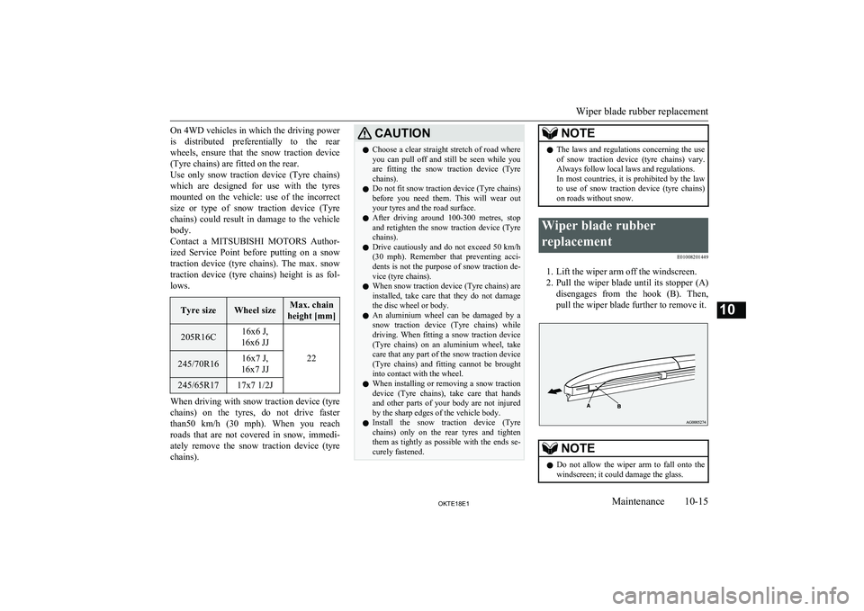
1. Lift the wiper arm off the windscreen.2. Pull the wiper blade until its stopper (A)
disengages from the hook (B). Then, pull the wiper blade further to remove it.
NOTEl Do not allow the wiper arm to fall onto the
windscreen; it could damage the glass.
Wiper blade rubber replacement
10-15OKTE18E1Maintenance10
Page 364 of 466
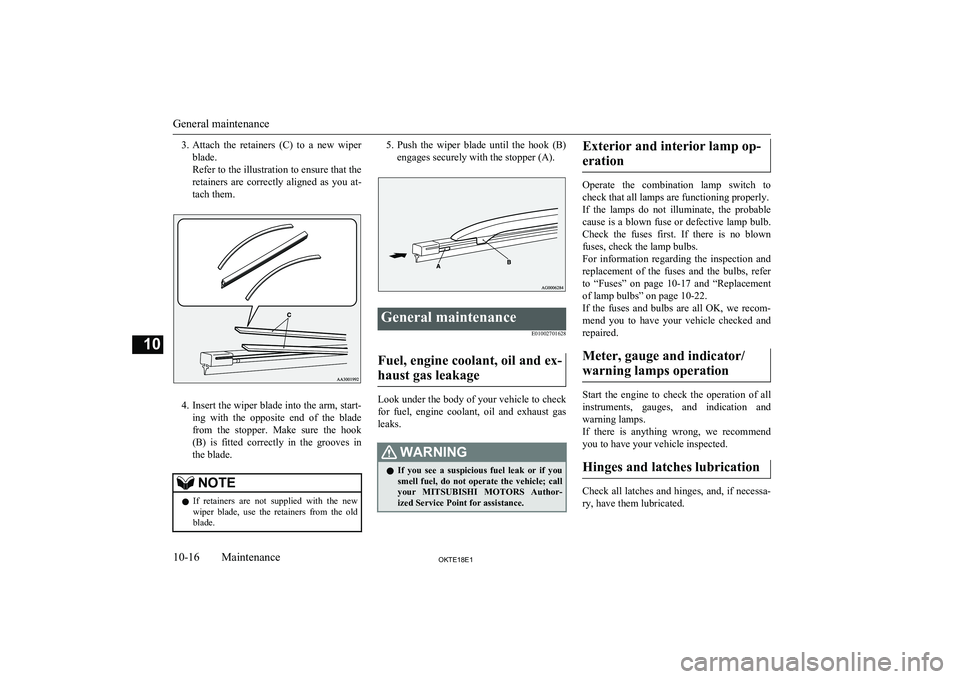
3.Attach the retainers (C) to a new wiper
blade.
Refer to the illustration to ensure that the
retainers are correctly aligned as you at- tach them.
4. Insert the wiper blade into the arm, start-
ing with the opposite end of the blade from the stopper. Make sure the hook
(B) is fitted correctly in the grooves inthe blade.
NOTEl If retainers are not supplied with the new
wiper blade, use the retainers from the old
blade.5. Push the wiper blade until the hook (B)
engages securely with the stopper (A).General maintenance
E01002701628
Fuel, engine coolant, oil and ex-
haust gas leakage
Look under the body of your vehicle to check
for fuel, engine coolant, oil and exhaust gas
leaks.
WARNINGl If you see a suspicious fuel leak or if you
smell fuel, do not operate the vehicle; call
your MITSUBISHI MOTORS Author-
ized Service Point for assistance.Exterior and interior lamp op-
eration
Operate the combination lamp switch to
check that all lamps are functioning properly.
If the lamps do not illuminate, the probable cause is a blown fuse or defective lamp bulb.
Check the fuses first. If there is no blown
fuses, check the lamp bulbs.
For information regarding the inspection and
replacement of the fuses and the bulbs, refer
to “Fuses” on page 10-17 and “Replacement
of lamp bulbs” on page 10-22.
If the fuses and bulbs are all OK, we recom-
mend you to have your vehicle checked and repaired.
Meter, gauge and indicator/ warning lamps operation
Start the engine to check the operation of all
instruments, gauges, and indication and warning lamps.
If there is anything wrong, we recommend
you to have your vehicle inspected.
Hinges and latches lubrication
Check all latches and hinges, and, if necessa- ry, have them lubricated.
General maintenance
10-16OKTE18E1Maintenance10
Page 371 of 466
Outside
E01003305254
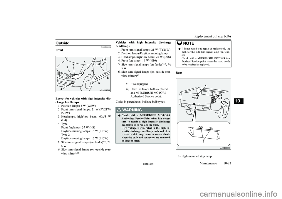
Front
Except for vehicles with high intensity dis-
charge headlamps 1. Position lamps: 5 W (W5W)
2. Front turn-signal lamps: 21 W (PY21W/
P21W)
3. Headlamps, high/low beam: 60/55 W
(H4)
4. Type 1 Front fog lamps: 35 W (H8)
Daytime running lamps: 13 W (P13W)
Type 2
Daytime running lamps: 13 W (P13W)
5. Side turn-signal lamps (on fender)* 1
, * 2
:
5 W
6. Side turn-signal lamps (on outside rear-
view mirror)* 1
Vehicles with high intensity discharge
headlamps 1. Front turn-signal lamps: 21 W (PY21W)
2. Position lamps/Daytime running lamps
3. Headlamps, high/low beam: 25 W (D5S) 4. Front fog lamps: 19 W (H16)
5. Side turn-signal lamps (on fender)* 1
, * 2
:
5 W
6. Side turn-signal lamps (on outside rear-
view mirror)* 1*1
:if so equipped* 2
:Have the lamps bulbs replaced
at a MITSUBISHI MOTORS
Authorized Service point.
Codes in parentheses indicate bulb types.
WARNINGl Check with a
MITSUBISHI MOTORS
Authorized Service Point when it is neces- sary to repair a high intensity discharge
headlamp or to replace the bulb.
High voltage is generated in the high in-
tensity discharge headlamp bulb and elec- trodes, which may cause a severe shock
when the bulb and connector are removed or disconnected.NOTEl It is not possible to repair or replace only the
bulb for the side turn-signal lamp (on fend-
er).
Check with a MITSUBISHI MOTORS Au-
thorized Service point when the lamp needs to be repaired or replaced.
Rear
1- High-mounted stop lamp
Replacement of lamp bulbs
10-23OKTE18E1Maintenance10
Page 379 of 466
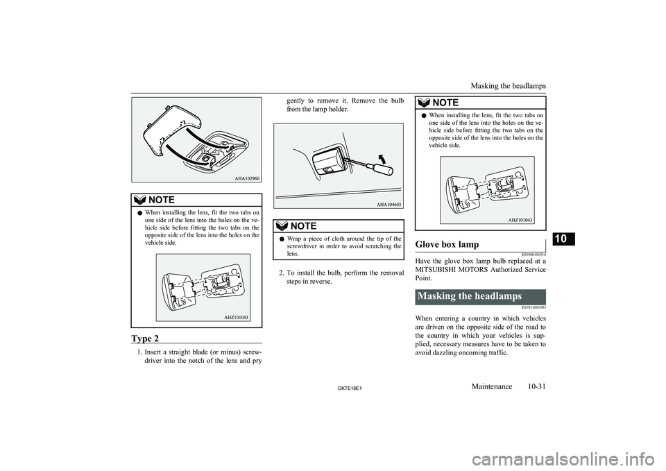
NOTElWhen installing the lens, fit the two tabs on
one side of the lens into the holes on the ve-hicle side before fitting the two tabs on the opposite side of the lens into the holes on the
vehicle side.
Type 2
1. Insert a straight blade (or minus) screw-
driver into the notch of the lens and pry
gently to remove it. Remove the bulb
from the lamp holder.NOTEl Wrap a piece of cloth around the tip of the
screwdriver in order to avoid scratching the
lens.
2. To install the bulb, perform the removal
steps in reverse.
NOTEl When installing the lens, fit the two tabs on
one side of the lens into the holes on the ve-hicle side before fitting the two tabs on the opposite side of the lens into the holes on the
vehicle side.Glove box lamp
E01006101516
Have the glove box lamp bulb replaced at a
MITSUBISHI MOTORS Authorized Service
Point.
Masking the headlamps
E01011601085
When entering a country in which vehiclesare driven on the opposite side of the road to the country in which your vehicles is sup-plied, necessary measures have to be taken to
avoid dazzling oncoming traffic.
Masking the headlamps
10-31OKTE18E1Maintenance10
Page 395 of 466
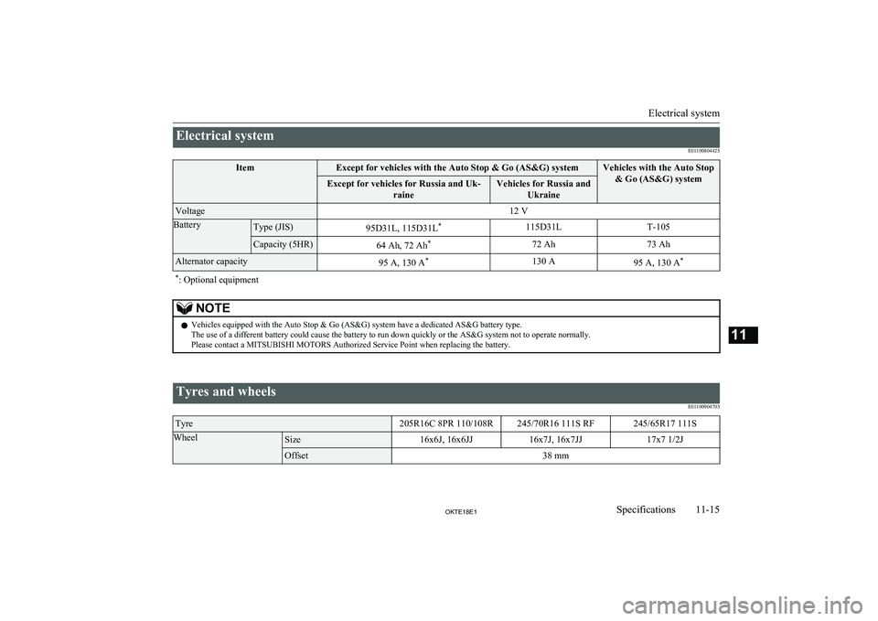
Electrical systemE01100804425ItemExcept for vehicles with the Auto Stop & Go (AS&G) systemVehicles with the Auto Stop& Go (AS&G) systemExcept for vehicles for Russia and Uk- raineVehicles for Russia andUkraineVoltage12 VBatteryType (JIS)95D31L, 115D31L *115D31LT-105Capacity (5HR)64 Ah, 72 Ah*72 Ah73 AhAlternator capacity95 A, 130 A*130 A95 A, 130 A**
: Optional equipmentNOTEl Vehicles equipped with the Auto Stop & Go (AS&G) system have a dedicated AS&G battery type.
The use of a different battery could cause the battery to run down quickly or the AS&G system not to operate normally.
Please contact a MITSUBISHI MOTORS Authorized Service Point when replacing the battery.
Tyres and wheels
E01100904703Tyre205R16C 8PR 110/108R245/70R16 111S RF245/65R17 111SWheelSize16x6J, 16x6JJ16x7J, 16x7JJ17x7 1/2JOffset38 mm
Electrical system
11-15OKTE18E1Specifications11
Page 396 of 466
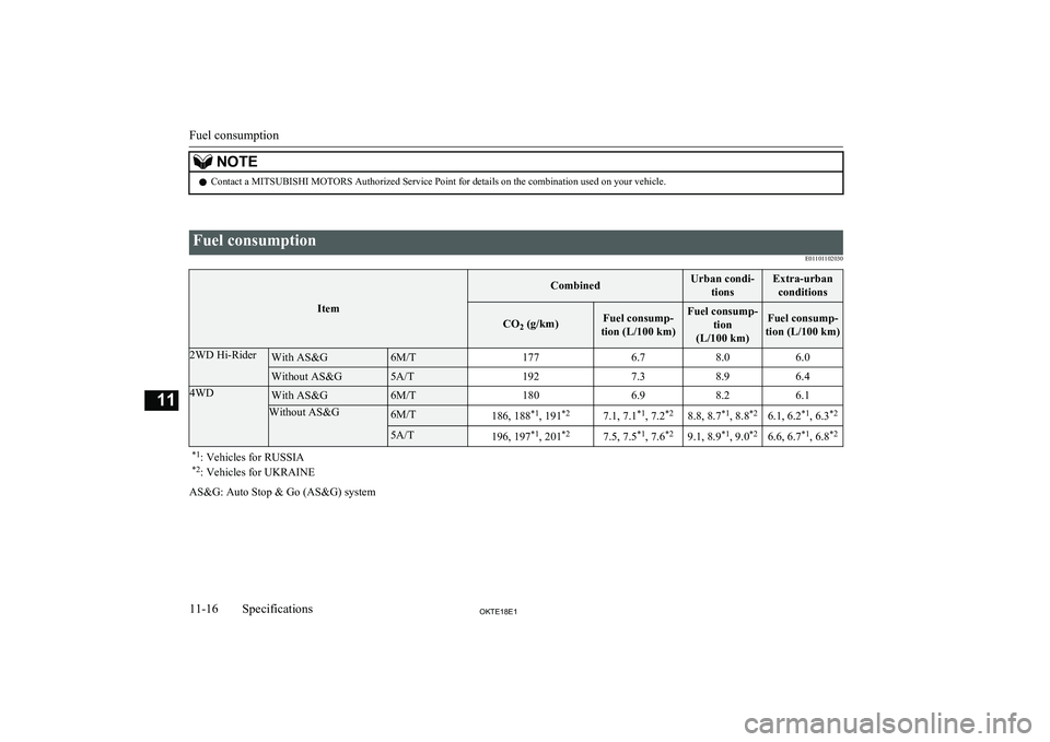
NOTElContact a MITSUBISHI MOTORS Authorized Service Point for details on the combination used on your vehicle.
Fuel consumption
E01101102030
Item
CombinedUrban condi-tionsExtra-urbanconditions
CO 2 (g/km)Fuel consump-
tion (L/100 km)Fuel consump- tion
(L/100 km)Fuel consump-
tion (L/100 km)2WD Hi-RiderWith AS&G6M/T1776.78.06.0Without AS&G5A/T1927.38.96.44WDWith AS&G6M/T1806.98.26.1Without AS&G6M/T186, 188 *1
, 191 *27.1, 7.1 *1
, 7.2 *28.8, 8.7 *1
, 8.8 *26.1, 6.2 *1
, 6.3 *25A/T196, 197 *1
, 201 *27.5, 7.5 *1
, 7.6 *29.1, 8.9 *1
, 9.0 *26.6, 6.7 *1
, 6.8 *2*1
: Vehicles for RUSSIA
*2 : Vehicles for UKRAINE
AS&G: Auto Stop & Go (AS&G) system
Fuel consumption
11-16OKTE18E1Specifications11
Page 405 of 466
Rear turn-signal lampsBulb capacity.............................................. 10-23
Indication lamp............................................. 5-13
Replacement................................................ 10-28
Switch........................................................... 5-20
Rear window demister switch........................... 5-27
Rear-view camera..............................................6-79
Rear-view mirror Inside............................................................. 6-08
Outside.......................................................... 6-09
Removal of water from the fuel filter................8-11
Replacement of lamp bulbs............................. 10-22
Reversing lamps Bulb capacity.............................................. 10-22
Replacement................................................ 10-28
Room lamp...................................................... 7-102
Running-in recommendations........................... 6-04
S
Safe driving techniques..................................... 6-03
Safety and disposal information for used engine oil................................................. 2-06
Seat belt............................................................. 4-07 Adjustable seat belt anchor........................... 4-09Child restraint................................................4-11Force limiter system...................................... 4-11
Inspection...................................................... 4-23
Pregnant women restraint............................. 4-10
Pretensioner system...................................... 4-10
Seat belt reminder..............................................4-08
Seat Adjustment.................................................... 4-02Armrest (Double cab)................................... 4-04
Front seats..................................................... 4-02
Head restraints.............................................. 4-05
Heated seats.................................................. 4-03
Rear seat........................................................ 4-04
Service precaution........................................... 10-02
Side turn-signal lamps Bulb capacity.............................................. 10-22Indication lamp............................................. 5-13
Switch........................................................... 5-21
Snow tyres....................................................... 10-14
Spare wheel....................................................... 8-17
Specifications.................................................. 11-02
Speed Limiter.................................................... 6-69 Switch........................................................... 6-69
Speed Limiter information on the multi information display area......................... 6-70
Starting.............................................................. 6-18
Steering wheel audio remote control switches................................................... 7-28,7-51
Steering Power steering fluid.......................... 10-09,11-17
Power steering system...................................6-58
Steering wheel height and reach adjustment. 6-07
Steering wheel lock....................................... 6-16
Stop lamps
Bulb capacity.............................................. 10-22
Replacement................................................ 10-28
Storage spaces................................................. 7-104
Centre console under tray........................... 7-105Floor console box........................................ 7-105Glove box.................................................... 7-104
Sunglasses holder........................................ 7-106
Sun visors.......................................................... 7-99
Sunglasses holder............................................ 7-106
Super Select 4WD II......................................... 6-40 2WD/4WD operation indication lamp.. 6-40,6-42Low-range indication lamp........................... 6-42
Supplemental restraint system...........................4-24
Curtain airbag system................................... 4-32
Driver’s and front passenger’s air- bag system................................................... 4-28
Driver’s knee airbag system..........................4-28
Front passenger’s airbag indicator................ 4-27
Front passenger’s airbag ON-OFF switch.... 4-27
How the Supplemental Restraint System works...............................................4-25
Servicing....................................................... 4-35
Side airbag system........................................ 4-31
Warning lamp................................................4-34
T
Tail lampsBulb capacity.............................................. 10-23
Replacement................................................ 10-28
Tank capacity.................................................... 2-03
Time Setting.............................................. 7-36,7-70
Tools.................................................................. 8-12 Storage.......................................................... 8-11
Towing.............................................................. 8-23
Trailer Stability Assist (TSA)........................... 6-62
Trailer towing.................................................... 6-84
Transfer oil...................................................... 11-17
Transmission Automatic transmission................................ 6-29Fluid............................................................ 11-17
Manual transmission..................................... 6-27
Turbocharger operation..................................... 6-23
Turn-signal indication lamps.............................5-13
Turn-signal lever............................................... 5-20
Tyres................................................................ 10-12
Alphabetical index
12- 5
OKTE18E1Alphabetical index