ect MITSUBISHI LANCER 2005 Owners Manual
[x] Cancel search | Manufacturer: MITSUBISHI, Model Year: 2005, Model line: LANCER, Model: MITSUBISHI LANCER 2005Pages: 788, PDF Size: 45.98 MB
Page 116 of 788
EMISSION CONTROL
ENGINE AND EMISSION CONTROL17-8
VACUUM HOSE CHECKM1173007300159
1. Using the piping diagram as a guide, check to be
sure that the vacuum hoses are correctly
connected.
2. Check the connection condition of the vacuum
hoses, (removed, loose, etc.) and check to be
sure that there are no bends or damage.
VACUUM HOSE INSTALLATIONM1173007200107
1. When connecting the vacuum hoses, they should
be securely inserted onto the nipples.
2. Connect the hoses correctly, using the vacuum
hose piping diagram as a guide.
CRANKCASE EMISSION CONTROL
SYSTEM
GENERAL INFORMATION (CRANKCASE
EMISSION CONTROL SYSTEM)
M1173005000237
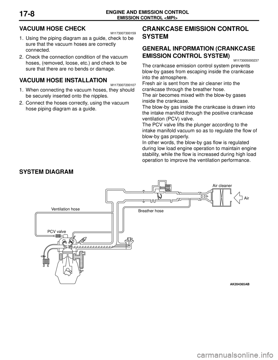
The crankcase emission control system prevents
blow-by gases from escaping inside the crankcase
into the atmosphere.
Fresh air is sent from the air cleaner into the
crankcase through the breather hose.
The air becomes mixed with the blow-by gases
inside the crankcase.
The blow-by gas inside the crankcase is drawn into
the intake manifold through the positive crankcase
ventilation (PCV) valve.
The PCV valve lifts the plunger according to the
intake manifold vacuum so as to regulate the flow of
blow-by gas properly.
In other words, the blow-by gas flow is regulated
during low load engine operation to maintain engine
stability, while the flow is increased during high load
operation to improve the ventilation performance.
SYSTEM DIAGRAM
AK204365
Air cleaner
Air
Ventilation hose
Breather hose
PCV valve
AB
Page 119 of 788
EMISSION CONTROL
ENGINE AND EMISSION CONTROL17-11
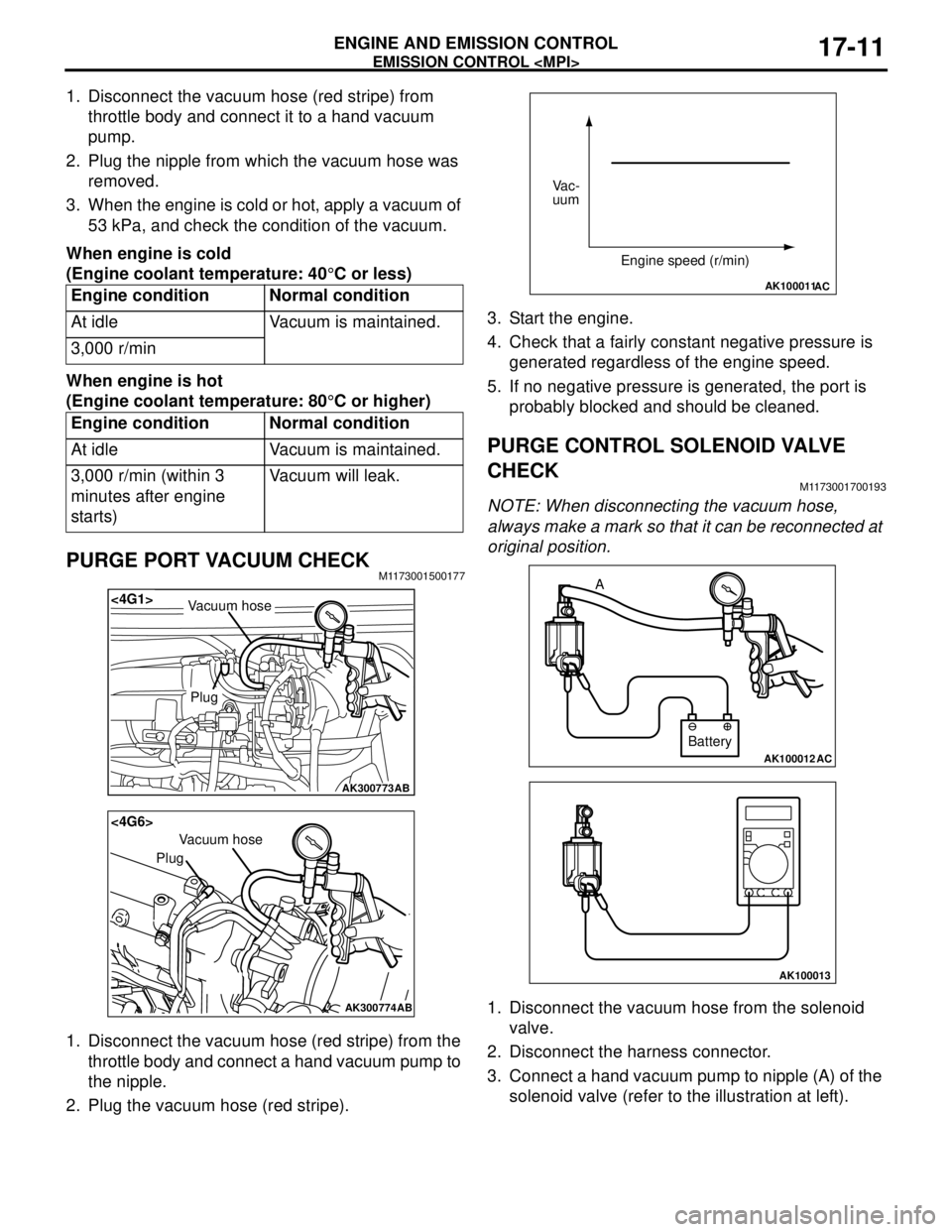
1. Disconnect the vacuum hose (red stripe) from
throttle body and connect it to a hand vacuum
pump.
2. Plug the nipple from which the vacuum hose was
removed.
3. When the engine is cold or hot, apply a vacuum of
53 kPa, and check the condition of the vacuum.
When engine is cold
(Engine coolant temperature: 40°C or less)
When engine is hot
(Engine coolant temperature: 80°C or higher)
PURGE PORT VACUUM CHECKM1173001500177
1. Disconnect the vacuum hose (red stripe) from the
throttle body and connect a hand vacuum pump to
the nipple.
2. Plug the vacuum hose (red stripe).3. Start the engine.
4. Check that a fairly constant negative pressure is
generated regardless of the engine speed.
5. If no negative pressure is generated, the port is
probably blocked and should be cleaned.
PURGE CONTROL SOLENOID VALVE
CHECK
M1173001700193
NOTE: When disconnecting the vacuum hose,
always make a mark so that it can be reconnected at
original position.
1. Disconnect the vacuum hose from the solenoid
valve.
2. Disconnect the harness connector.
3. Connect a hand vacuum pump to nipple (A) of the
solenoid valve (refer to the illustration at left). Engine condition Normal condition
At idle Vacuum is maintained.
3,000 r/min
Engine condition Normal condition
At idle Vacuum is maintained.
3,000 r/min (within 3
minutes after engine
starts)Vacuum will leak.
AK300773
<4G1>
AB
Plug
Vacuum hose
AK300774
<4G6>
AB
Plug
Vacuum hose
AK100011AC
Vac-
uum
Engine speed (r/min)
AK100012AC
Battery A
AK100013
Page 120 of 788
EMISSION CONTROL
ENGINE AND EMISSION CONTROL17-12
4. Check airtightness by applying a vacuum with
voltage applied directly from the battery to the
purge control solenoid valve and without applying
voltage.
5. Measure the resistance between the terminals of
the solenoid valve.
Standard value: 30 − 34 Ω (at 20°C)
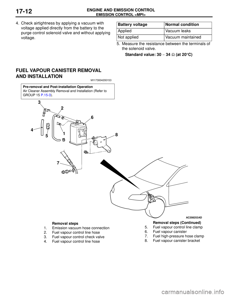
FUEL VAPOUR CANISTER REMOVAL
AND INSTALLATION
M1173004200153
Battery voltage Normal condition
Applied Vacuum leaks
Not applied Vacuum maintained
Pre-removal and Post-installation Operation
Air Cleaner Assembly Removal and Installation (Refer to
GROUP 15 P.15-3).
AC208253
1 2 3
4
56
78
AD
Removal steps
1. Emission vacuum hose connection
2. Fuel vapour control line hose
3. Fuel vapour control check valve
4. Fuel vapour control line hose5. Fuel vapour control line clamp
6. Fuel vapour canister
7. Fuel high-pressure hose clamp
8. Fuel vapour canister bracketRemoval steps (Continued)
Page 123 of 788
EMISSION CONTROL
ENGINE AND EMISSION CONTROL17-15
EGR SYSTEM CHECKM1173002600348
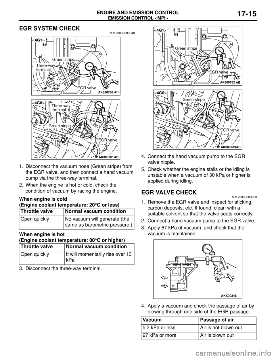
1. Disconnect the vacuum hose (Green stripe) from
the EGR valve, and then connect a hand vacuum
pump via the three-way terminal.
2. When the engine is hot or cold, check the
condition of vacuum by racing the engine.
When engine is cold
(Engine coolant temperature: 20°C or less)
When engine is hot
(Engine coolant temperature: 80°C or higher)
3. Disconnect the three-way terminal.4. Connect the hand vacuum pump to the EGR
valve nipple.
5. Check whether the engine stalls or the idling is
unstable when a vacuum of 30 kPa or higher is
applied during idling.
EGR VALVE CHECKM1173002800223
1. Remove the EGR valve and inspect for sticking,
carbon deposits, etc. If found, clean with a
suitable solvent so that the valve seats correctly.
2. Connect a hand vacuum pump to the EGR valve.
3. Apply 67 kPa of vacuum, and check that the
vacuum is maintained.
4. Apply a vacuum and check the passage of air by
blowing through one side of the EGR passage. Throttle valve Normal vacuum condition
Open quickly No vacuum will generate (the
same as barometric pressure.)
Throttle valve Normal vacuum condition
Open quickly It will momentarily rise over 13
kPa
AK300780AB
<4G1>
EGR valve
Green stripe
Three-way
terminal
AK300781AB
<4G6>
EGR valve
Green stripe
Three-way
terminal
Vacuum Passage of air
5.3 kPa or less Air is not blown out
27 kPa or more Air is blown out
AK300782AB
<4G1>
EGR valve
Green stripe
AK300783AB
<4G6>
EGR valve
Green stripe
AKX00348
Page 124 of 788
EMISSION CONTROL
ENGINE AND EMISSION CONTROL17-16
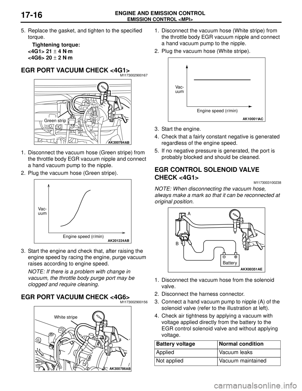
5. Replace the gasket, and tighten to the specified
torque.
Tightening torque:
<4G1> 21 ± 4 N⋅m
<4G6> 20 ± 2 N⋅m
EGR PORT VACUUM CHECK <4G1>M1173002900167
1. Disconnect the vacuum hose (Green stripe) from
the throttle body EGR vacuum nipple and connect
a hand vacuum pump to the nipple.
2. Plug the vacuum hose (Green stripe).
3. Start the engine and check that, after raising the
engine speed by racing the engine, purge vacuum
raises according to engine speed.
NOTE: If there is a problem with change in
vacuum, the throttle body purge port may be
clogged and require cleaning.
EGR PORT VACUUM CHECK <4G6>M1173002900156
1. Disconnect the vacuum hose (White stripe) from
the throttle body EGR vacuum nipple and connect
a hand vacuum pump to the nipple.
2. Plug the vacuum hose (White stripe).
3. Start the engine.
4. Check that a fairly constant negative is generated
regardless of the engine speed.
5. If no negative pressure is generated, the port is
probably blocked and should be cleaned.
EGR CONTROL SOLENOID VALVE
CHECK <4G1>
M1173003100238
NOTE: When disconnecting the vacuum hose,
always make a mark so that it can be reconnected at
original position.
1. Disconnect the vacuum hose from the solenoid
valve.
2. Disconnect the harness connector.
3. Connect a hand vacuum pump to nipple (A) of the
solenoid valve (refer to the illustration at left).
4. Check air tightness by applying a vacuum with
voltage applied directly from the battery to the
EGR control solenoid valve and without applying
voltage.
AK300784AB
Green strip
AK201224AB
Vac-
uum
Engine speed (r/min)
AK300786AB
White stripe
Battery voltage Normal condition
Applied Vacuum leaks
Not applied Vacuum maintained
AK100011AC
Vac-
uum
Engine speed (r/min)
AKX00351
A
B
AE
Battery
Page 125 of 788

EMISSION CONTROL
ENGINE AND EMISSION CONTROL17-17
5. Measure the resistance between the terminals of
the solenoid valve.
Standard value: 29 − 35 Ω (at 20°C)
EGR CONTROL SOLENOID VALVE
CHECK <4G6>
M1173003100249
NOTE: When disconnecting the vacuum hose,
always make a mark so that it can be reconnected at
original position.1. Disconnect the vacuum hose from the solenoid
valve.
2. Disconnect the harness connector.
3. Connect a hand vacuum pump to nipple (A) of the
solenoid valve (refer to the illustration at left).
4. Check air tightness by applying a vacuum with
voltage applied directly from the battery to the
EGR control solenoid valve and without applying
voltage.
5. Measure the resistance between the terminals of
the solenoid valve.
Standard value: 29 − 35 Ω (at 20°C)
AKX00352
AK201251AB
A
B
C
Battery
Battery
voltageB nipple
conditionNormal condition
Not applied Open Vacuum
maintained
Applied Open Vacuum leaks
Closed Vacuum
maintained
AK100016
Page 126 of 788
EMISSION CONTROL
ENGINE AND EMISSION CONTROL17-18
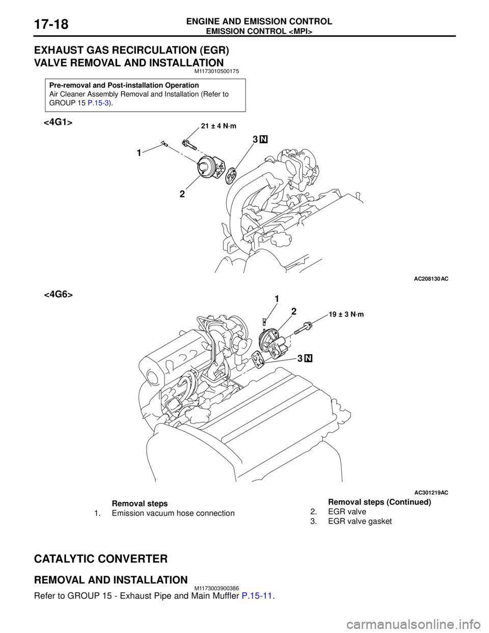
EXHAUST GAS RECIRCULATION (EGR)
VALVE REMOVAL AND INSTALLATION
M1173010500175
CATALYTIC CONVERTER
REMOVAL AND INSTALLATIONM1173003900386
Refer to GROUP 15 - Exhaust Pipe and Main Muffler P.15-11.
Pre-removal and Post-installation Operation
Air Cleaner Assembly Removal and Installation (Refer to
GROUP 15 P.15-3).
AC208130
21 ± 4 N·m
2 13
N
AC
<4G1>
AC301219
19 ± 3 N·m2 1
3
N
AC
<4G6>
Removal steps
1. Emission vacuum hose connection2. EGR valve
3. EGR valve gasketRemoval steps (Continued)
Page 133 of 788
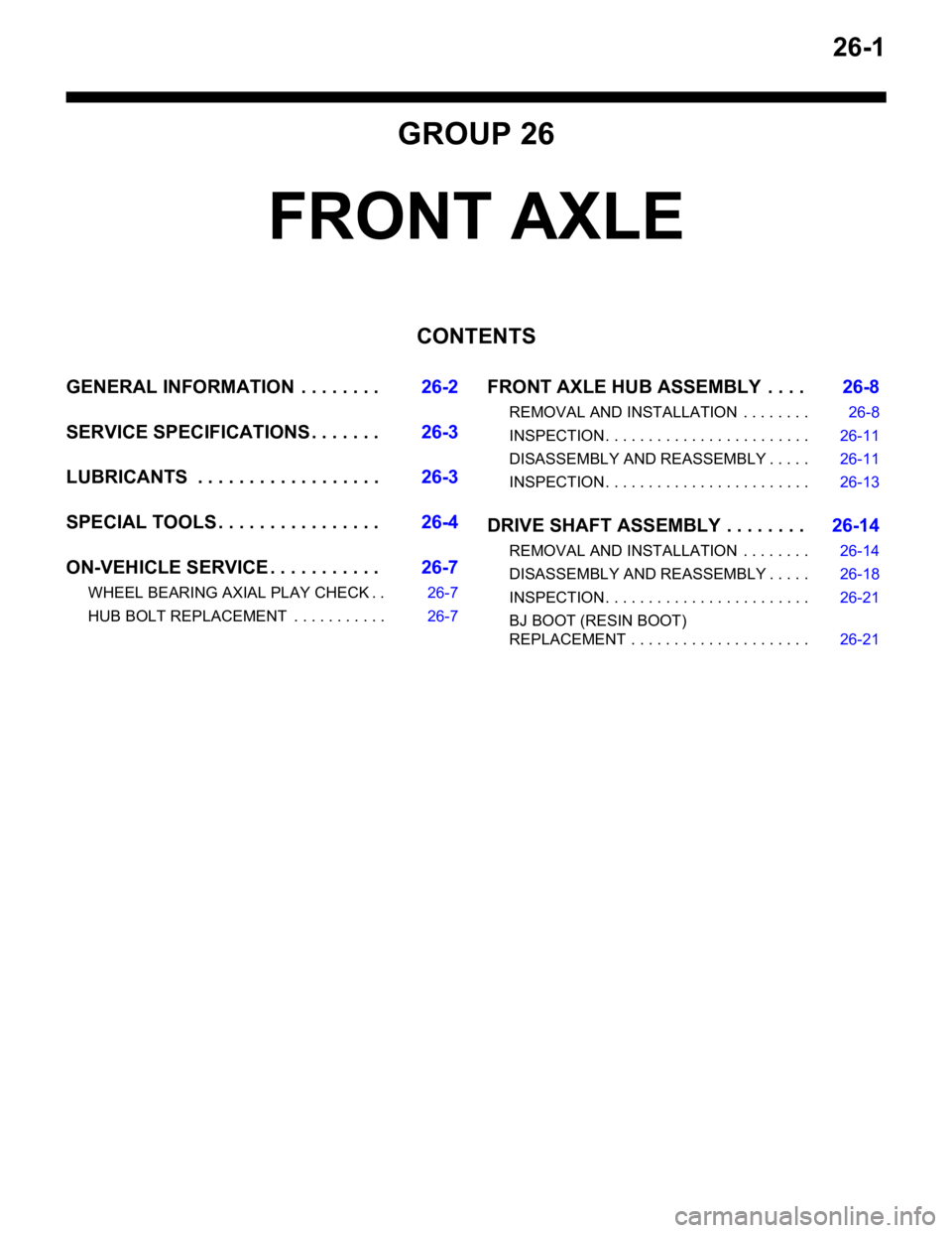
26-1
GROUP 26
FRONT AXLE
CONTENTS
GENERAL INFORMATION . . . . . . . .26-2
SERVICE SPECIFICATIONS . . . . . . .26-3
LUBRICANTS . . . . . . . . . . . . . . . . . .26-3
SPECIAL TOOLS . . . . . . . . . . . . . . . .26-4
ON-VEHICLE SERVICE . . . . . . . . . . .26-7
WHEEL BEARING AXIAL PLAY CHECK . . 26-7
HUB BOLT REPLACEMENT . . . . . . . . . . . 26-7
FRONT AXLE HUB ASSEMBLY . . . .26-8
REMOVAL AND INSTALLATION . . . . . . . . 26-8
INSPECTION . . . . . . . . . . . . . . . . . . . . . . . . 26-11
DISASSEMBLY AND REASSEMBLY . . . . . 26-11
INSPECTION . . . . . . . . . . . . . . . . . . . . . . . . 26-13
DRIVE SHAFT ASSEMBLY . . . . . . . .26-14
REMOVAL AND INSTALLATION . . . . . . . . 26-14
DISASSEMBLY AND REASSEMBLY . . . . . 26-18
INSPECTION . . . . . . . . . . . . . . . . . . . . . . . . 26-21
BJ BOOT (RESIN BOOT)
REPLACEMENT . . . . . . . . . . . . . . . . . . . . . 26-21
Page 134 of 788
GENERAL INFORMATION
FRONT AXLE26-2
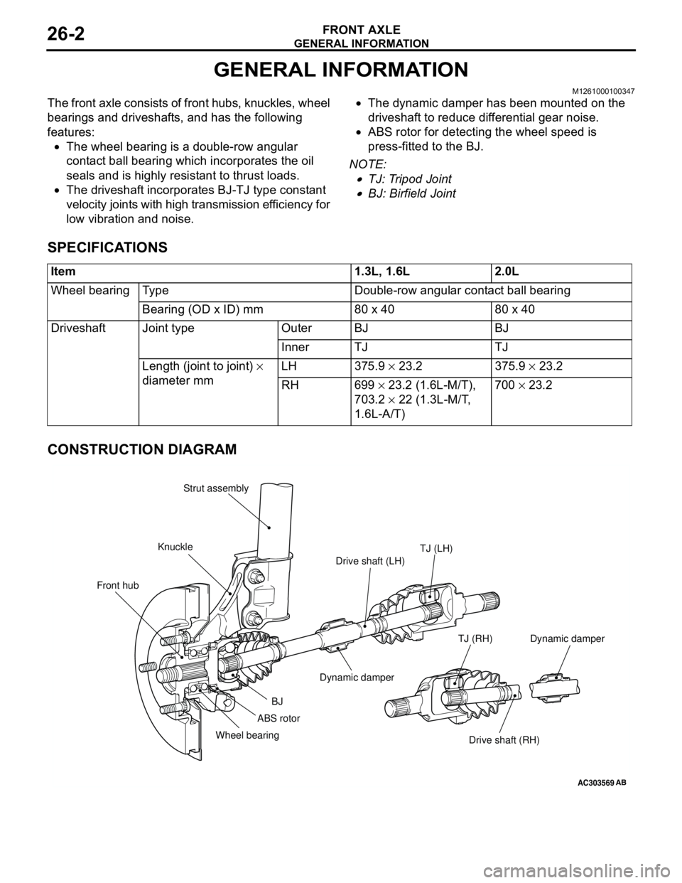
GENERAL INFORMATION
M1261000100347
The front axle consists of front hubs, knuckles, wheel
bearings and driveshafts, and has the following
features:
•The wheel bearing is a double-row angular
contact ball bearing which incorporates the oil
seals and is highly resistant to thrust loads.
•The driveshaft incorporates BJ-TJ type constant
velocity joints with high transmission efficiency for
low vibration and noise.•The dynamic damper has been mounted on the
driveshaft to reduce differential gear noise.
•ABS rotor for detecting the wheel speed is
press-fitted to the BJ.
NOTE: .
•TJ: Tripod Joint
•BJ: Birfield Joint
SPECIFICATIONS
CONSTRUCTION DIAGRAM
Item 1.3L, 1.6L 2.0L
Wheel bearing Type Double-row angular contact ball bearing
Bearing (OD x ID) mm 80 x 40 80 x 40
Driveshaft Joint type Outer BJ BJ
Inner TJ TJ
Length (joint to joint) ×
diameter mm LH 375.9 × 23.2 375.9 × 23.2
RH 699 × 23.2 (1.6L-M/T),
703.2 × 22 (1.3L-M/T,
1.6L-A/T)700 × 23.2
AC303569
Front hubKnuckleStrut assembly
TJ (LH)
Drive shaft (LH)
Dynamic damper
BJ
Wheel bearing
Drive shaft (RH) TJ (RH)
AB
ABS rotorDynamic damper
Page 136 of 788
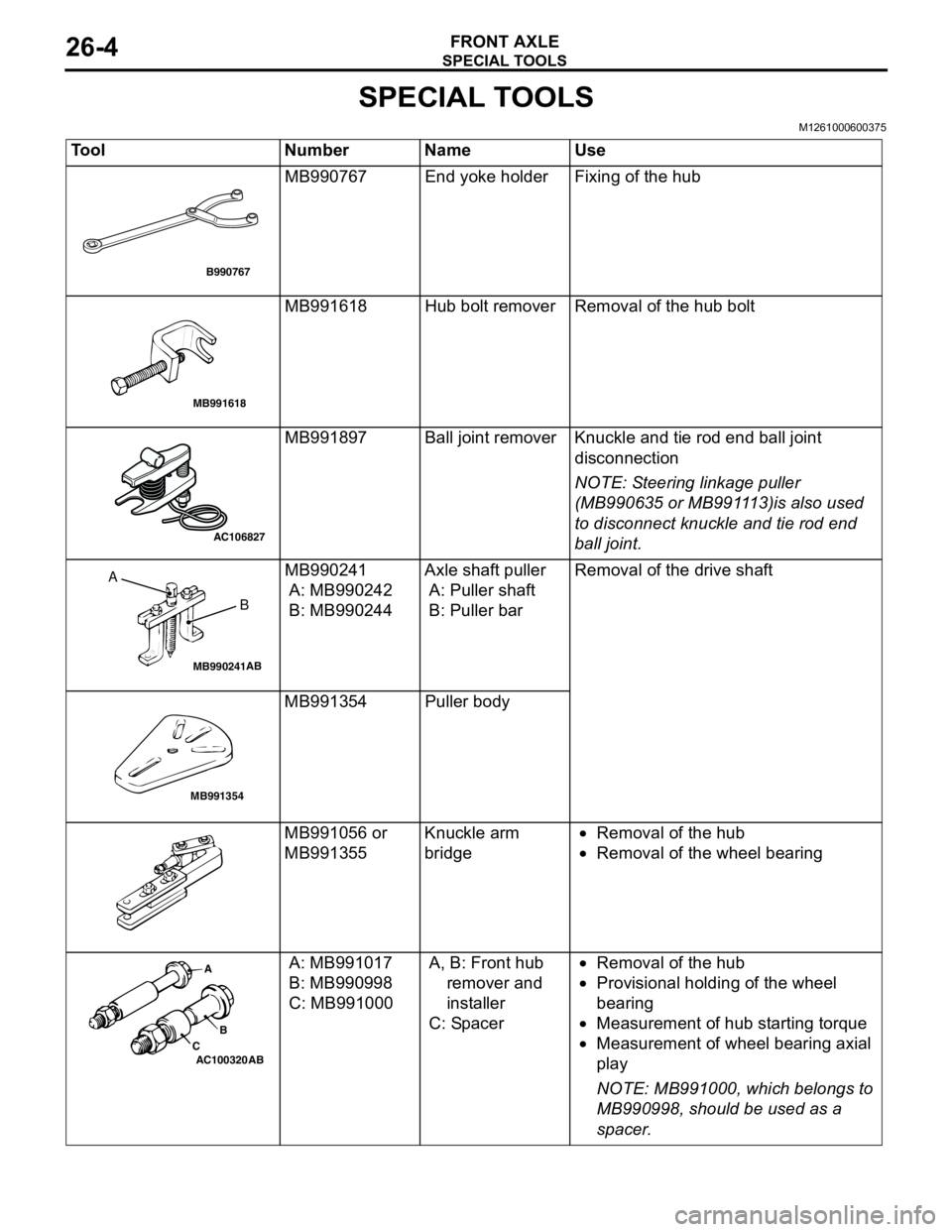
SPECIAL TOOLS
FRONT AXLE26-4
SPECIAL TOOLS
M1261000600375
Tool Number Name Use
MB990767 End yoke holder Fixing of the hub
MB991618 Hub bolt remover Removal of the hub bolt
MB991897 Ball joint remover Knuckle and tie rod end ball joint
disconnection
NOTE: Steering linkage puller
(MB990635 or MB991113)is also used
to disconnect knuckle and tie rod end
ball joint.
MB990241
A: MB990242
B: MB990244Axle shaft puller
A: Puller shaft
B: Puller barRemoval of the drive shaft
MB991354 Puller body
MB991056 or
MB991355Knuckle arm
bridge•Removal of the hub
•Removal of the wheel bearing
A: MB991017
B: MB990998
C: MB991000A, B: Front hub
remover and
installer
C: Spacer•Removal of the hub
•Provisional holding of the wheel
bearing
•Measurement of hub starting torque
•Measurement of wheel bearing axial
play
NOTE: MB991000, which belongs to
MB990998, should be used as a
spacer.
B990767
MB991618
AC106827
MB990241AB
A
B
MB991354
AC100320 ABA
B
C