length MITSUBISHI LANCER 2005 Workshop Manual
[x] Cancel search | Manufacturer: MITSUBISHI, Model Year: 2005, Model line: LANCER, Model: MITSUBISHI LANCER 2005Pages: 788, PDF Size: 45.98 MB
Page 43 of 788
WAT ER P U M P
ENGINE COOLING14-29
WAT E R P U M P
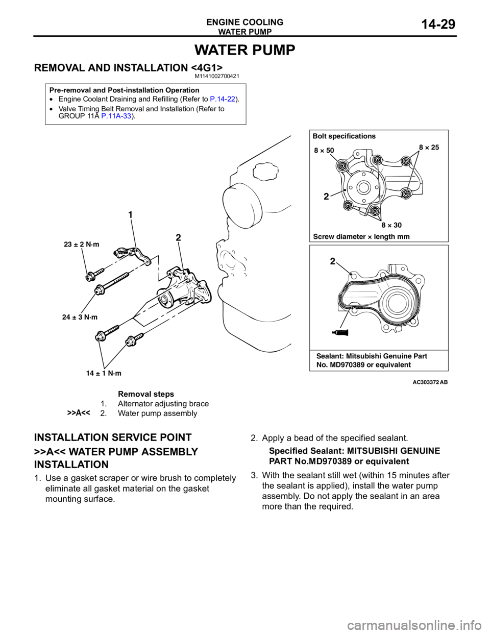
REMOVAL AND INSTALLATION <4G1>M1141002700421
INSTALLATION SERVICE POINT
>>A<< WATER PUMP ASSEMBLY
INSTALLATION
1. Use a gasket scraper or wire brush to completely
eliminate all gasket material on the gasket
mounting surface.2. Apply a bead of the specified sealant.
Specified Sealant: MITSUBISHI GENUINE
PART No.MD970389 or equivalent
3. With the sealant still wet (within 15 minutes after
the sealant is applied), install the water pump
assembly. Do not apply the sealant in an area
more than the required.
Pre-removal and Post-installation Operation
•Engine Coolant Draining and Refilling (Refer to P.14-22).
•Valve Timing Belt Removal and Installation (Refer to
GROUP 11A P.11A-33).
AC303372
24 ± 3 N·m 23 ± 2 N·m
14 ± 1 N·m
1
2
Bolt specifications
Screw diameter × length mm 8 × 50
8 × 308 × 25
AB
2
2
Sealant: Mitsubishi Genuine Part
No. MD970389 or equivalent
Removal steps
1. Alternator adjusting brace
>>A<<2. Water pump assembly
Page 44 of 788
WAT E R P U M P
ENGINE COOLING14-30
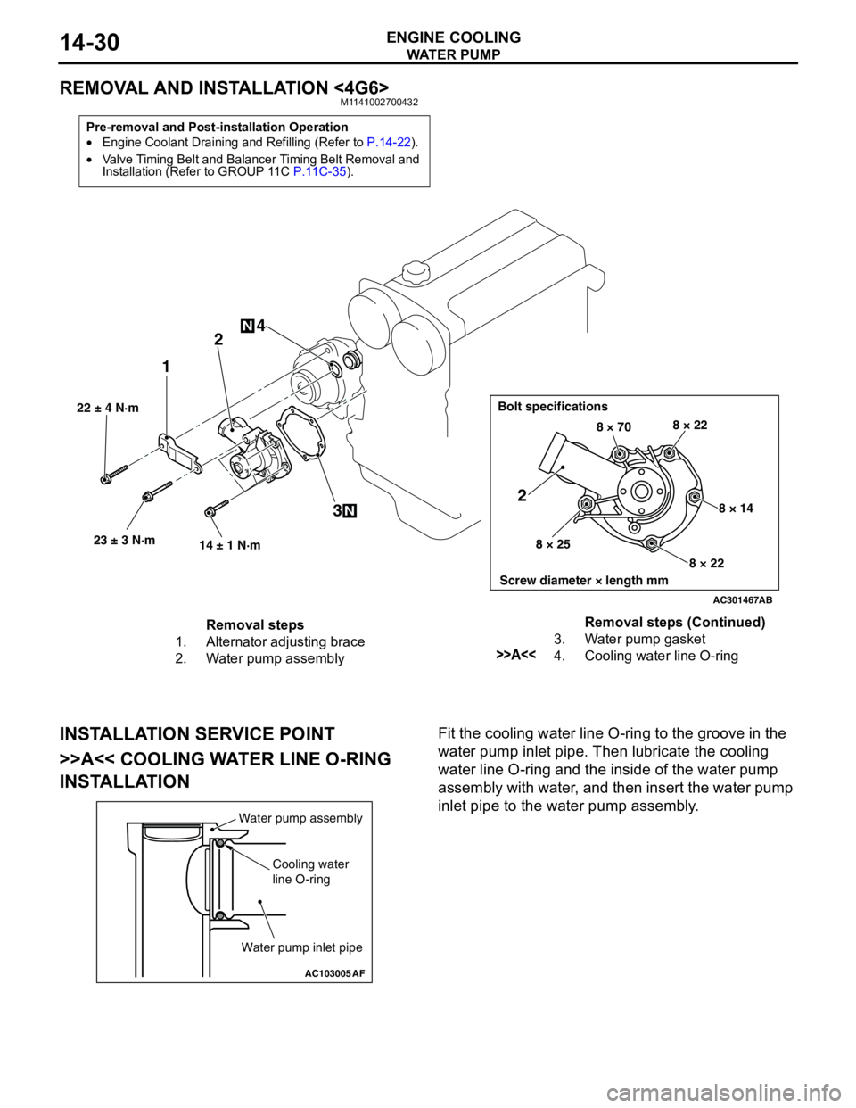
REMOVAL AND INSTALLATION <4G6>M1141002700432
INSTALLATION SERVICE POINT
>>A<< COOLING WATER LINE O-RING
INSTALLATIONFit the cooling water line O-ring to the groove in the
water pump inlet pipe. Then lubricate the cooling
water line O-ring and the inside of the water pump
assembly with water, and then insert the water pump
inlet pipe to the water pump assembly.
Pre-removal and Post-installation Operation
•Engine Coolant Draining and Refilling (Refer to P.14-22).
•Valve Timing Belt and Balancer Timing Belt Removal and
Installation (Refer to GROUP 11C P.11C-35).
AC301467
22 ± 4 N·m
23 ± 3 N·m
14 ± 1 N·m
12
3 4
N
N
Bolt specifications
Screw diameter × length mm
8 × 708 × 22
8 × 14
8 × 22 8 × 25
2
AB
Removal steps
1. Alternator adjusting brace
2. Water pump assembly3. Water pump gasket
>>A<<4. Cooling water line O-ringRemoval steps (Continued)
AC103005
Water pump assembly
Cooling water
line O-ring
Water pump inlet pipe
AF
Page 82 of 788
CHARGING SYSTEM
ENGINE ELECTRICAL16-18
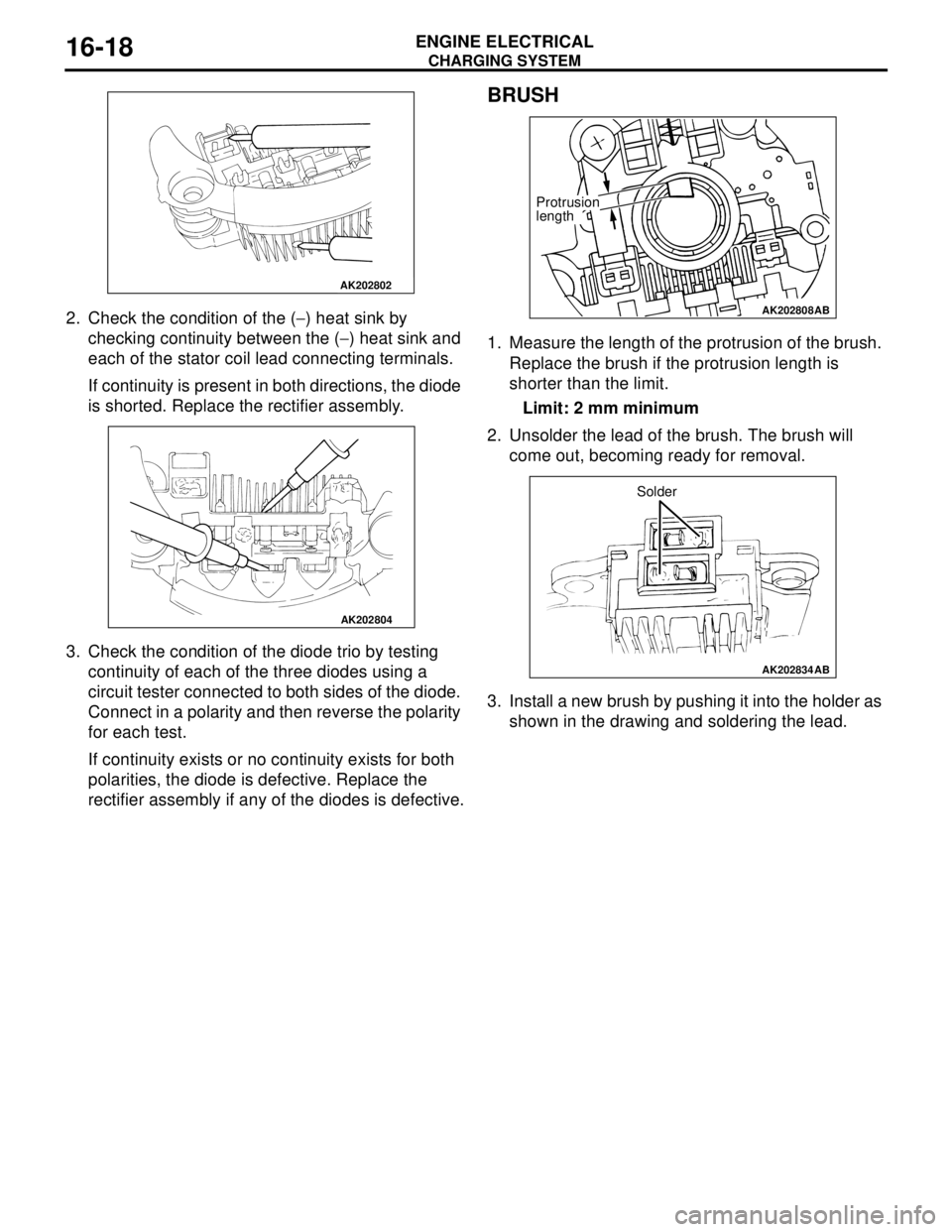
2. Check the condition of the (−) heat sink by
checking continuity between the (−) heat sink and
each of the stator coil lead connecting terminals.
If continuity is present in both directions, the diode
is shorted. Replace the rectifier assembly.
3. Check the condition of the diode trio by testing
continuity of each of the three diodes using a
circuit tester connected to both sides of the diode.
Connect in a polarity and then reverse the polarity
for each test.
If continuity exists or no continuity exists for both
polarities, the diode is defective. Replace the
rectifier assembly if any of the diodes is defective.
BRUSH
1. Measure the length of the protrusion of the brush.
Replace the brush if the protrusion length is
shorter than the limit.
Limit: 2 mm minimum
2. Unsolder the lead of the brush. The brush will
come out, becoming ready for removal.
3. Install a new brush by pushing it into the holder as
shown in the drawing and soldering the lead.
AK202802
AK202804
AK202808
Protrusion
length
AB
AK202834
Solder
AB
Page 99 of 788
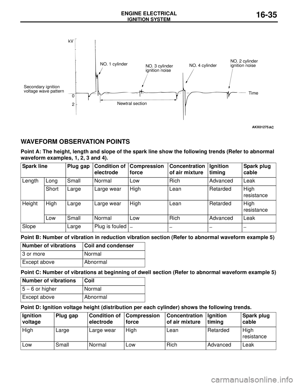
IGNITION SYSTEM
ENGINE ELECTRICAL16-35
WAVEFORM OBSERVATION POINTS
Point A: The height, length and slope of the spark line show the following trends (Refer to abnormal
waveform examples, 1, 2, 3 and 4).
Point B: Number of vibration in reduction vibration section (Refer to abnormal waveform example 5)
Point C: Number of vibrations at beginning of dwell section (Refer to abnormal waveform example 5)
Point D: Ignition voltage height (distribution per each cylinder) shows the following trends.
AKX01275
kV
Secondary ignition
voltage wave pattern
0
2NO. 1 cylinder
NO. 3 cylinder
ignition noise
Newtral sectionNO. 4 cylinderNO. 2 cylinder
ignition noise
Time
AC
Spark line Plug gap Condition of
electrodeCompression
force Concentration
of air mixtureIgnition
timingSpark plug
cable
Length Long Small Normal Low Rich Advanced Leak
Short Large Large wear High Lean Retarded High
resistance
Height High Large Large wear High Lean Retarded High
resistance
Low Small Normal Low Rich Advanced Leak
Slope Large Plug is fouled
−− −−
Number of vibrations Coil and condenser
3 or more Normal
Except above Abnormal
Number of vibrations Coil
5 − 6 or higher Normal
Except above Abnormal
Ignition
voltagePlug gap Condition of
electrodeCompression
forceConcentration
of air mixtureIgnition
timingSpark plug
cable
High Large Large wear High Lean Retarded High
resistance
Low Small Normal Low Rich Advanced Leak
Page 134 of 788
GENERAL INFORMATION
FRONT AXLE26-2
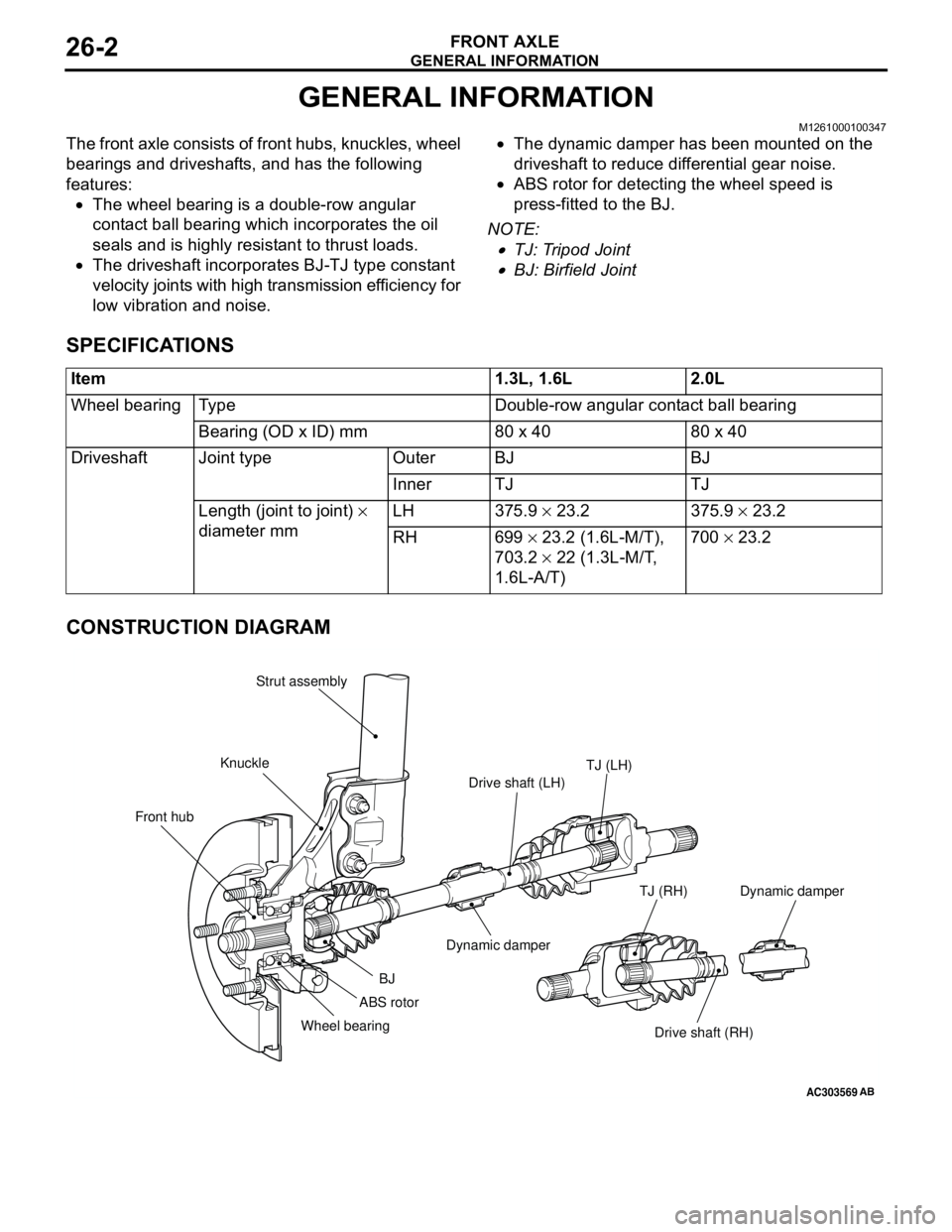
GENERAL INFORMATION
M1261000100347
The front axle consists of front hubs, knuckles, wheel
bearings and driveshafts, and has the following
features:
•The wheel bearing is a double-row angular
contact ball bearing which incorporates the oil
seals and is highly resistant to thrust loads.
•The driveshaft incorporates BJ-TJ type constant
velocity joints with high transmission efficiency for
low vibration and noise.•The dynamic damper has been mounted on the
driveshaft to reduce differential gear noise.
•ABS rotor for detecting the wheel speed is
press-fitted to the BJ.
NOTE: .
•TJ: Tripod Joint
•BJ: Birfield Joint
SPECIFICATIONS
CONSTRUCTION DIAGRAM
Item 1.3L, 1.6L 2.0L
Wheel bearing Type Double-row angular contact ball bearing
Bearing (OD x ID) mm 80 x 40 80 x 40
Driveshaft Joint type Outer BJ BJ
Inner TJ TJ
Length (joint to joint) ×
diameter mm LH 375.9 × 23.2 375.9 × 23.2
RH 699 × 23.2 (1.6L-M/T),
703.2 × 22 (1.3L-M/T,
1.6L-A/T)700 × 23.2
AC303569
Front hubKnuckleStrut assembly
TJ (LH)
Drive shaft (LH)
Dynamic damper
BJ
Wheel bearing
Drive shaft (RH) TJ (RH)
AB
ABS rotorDynamic damper
Page 135 of 788
SERVICE SPECIFICATIONS
FRONT AXLE26-3
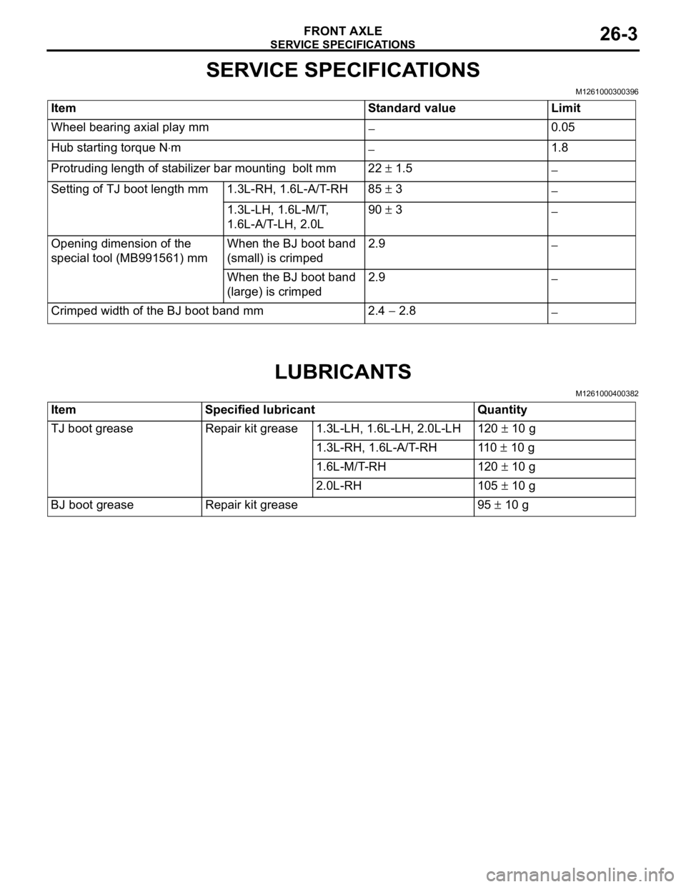
SERVICE SPECIFICATIONS
M1261000300396
LUBRICANTS
M1261000400382
Item Standard value Limit
Wheel bearing axial play mm
−0.05
Hub starting torque N⋅m
−1.8
Protruding length of stabilizer bar mounting bolt mm 22 ± 1.5
−
Setting of TJ boot length mm 1.3L-RH, 1.6L-A/T-RH 85 ± 3
−
1.3L-LH, 1.6L-M/T,
1.6L-A/T-LH, 2.0L90 ± 3
−
Opening dimension of the
special tool (MB991561) mmWhen the BJ boot band
(small) is crimped2.9
−
When the BJ boot band
(large) is crimped2.9
−
Crimped width of the BJ boot band mm 2.4 − 2.8
−
Item Specified lubricant Quantity
TJ boot grease Repair kit grease 1.3L-LH, 1.6L-LH, 2.0L-LH 120 ± 10 g
1.3L-RH, 1.6L-A/T-RH 110 ± 10 g
1.6L-M/T-RH 120 ± 10 g
2.0L-RH 105 ± 10 g
BJ boot grease Repair kit grease 95 ± 10 g
Page 142 of 788
FRONT AXLE HUB ASSEMBLY
FRONT AXLE26-10
<
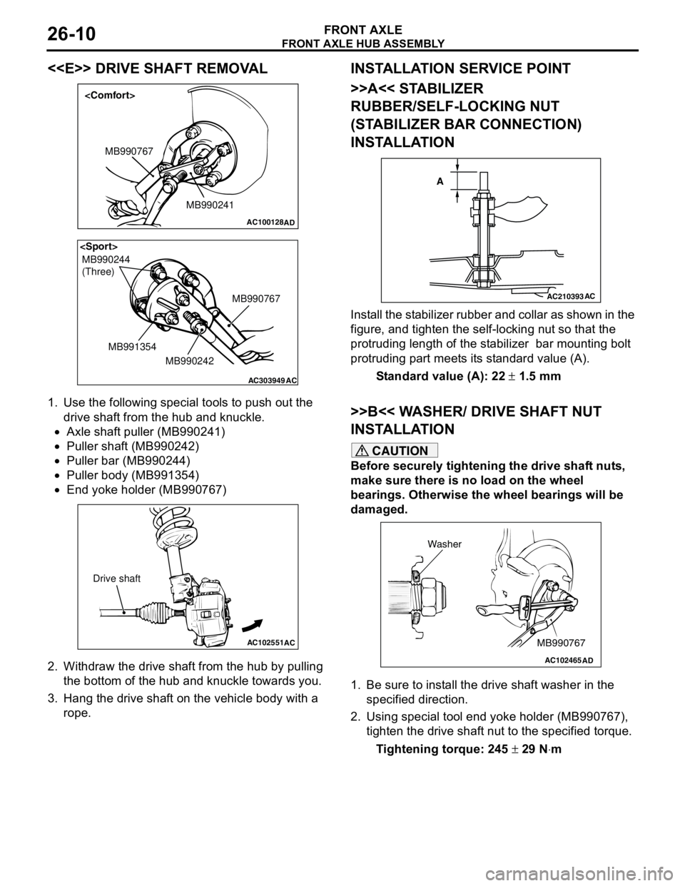
1. Use the following special tools to push out the
drive shaft from the hub and knuckle.
•Axle shaft puller (MB990241)
•Puller shaft (MB990242)
•Puller bar (MB990244)
•Puller body (MB991354)
•End yoke holder (MB990767)
2. Withdraw the drive shaft from the hub by pulling
the bottom of the hub and knuckle towards you.
3. Hang the drive shaft on the vehicle body with a
rope.
INSTALLATION SERVICE POINT
>>A<< STABILIZER
RUBBER/SELF-LOCKING NUT
(STABILIZER BAR CONNECTION)
INSTALLATION
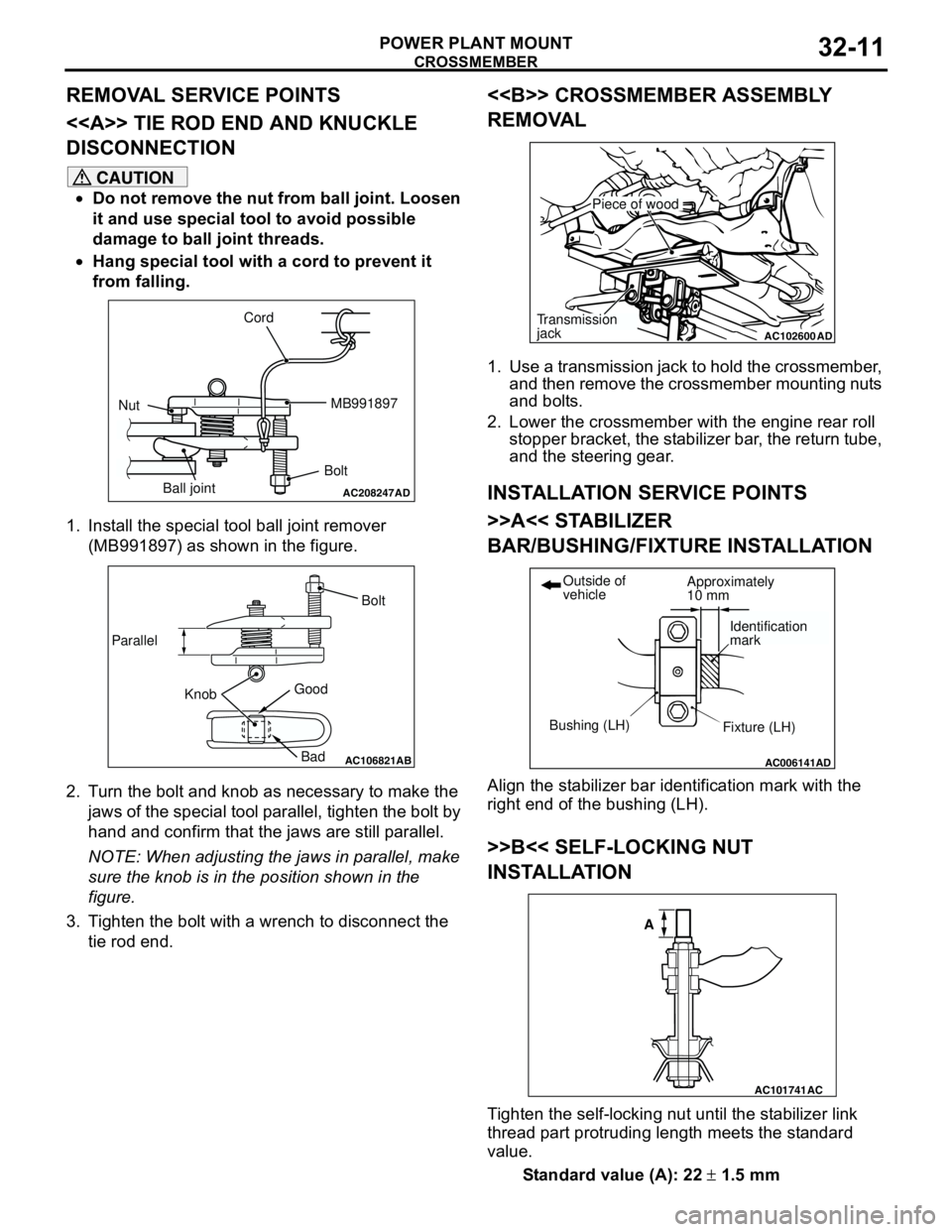
Install the stabilizer rubber and collar as shown in the
figure, and tighten the self-locking nut so that the
protruding length of the stabilizer bar mounting bolt
protruding part meets its standard value (A).
Standard value (A): 22 ± 1.5 mm
>>B<< WASHER/ DRIVE SHAFT NUT
INSTALLATION
CAUTION
Before securely tightening the drive shaft nuts,
make sure there is no load on the wheel
bearings. Otherwise the wheel bearings will be
damaged.
1. Be sure to install the drive shaft washer in the
specified direction.
2. Using special tool end yoke holder (MB990767),
tighten the drive shaft nut to the specified torque.
Tightening torque: 245 ± 29 N⋅m
AC100128
MB990241 MB990767
AD
AC303949
MB990244
(Three)
MB990767
MB990242 MB991354
AC
AC102551
AC
Drive shaft
AC210393AC
A
AC102465AD
MB990767 Washer
Page 149 of 788
DRIVE SHAFT ASSEMBLY
FRONT AXLE26-17
INSTALLATION SERVICE POINTS
>>A<< DRIVE SHAFT INSTALLATION
CAUTION
When installing the drive shaft, be careful that
the spline part of the drive shaft does not
damage the oil seal.
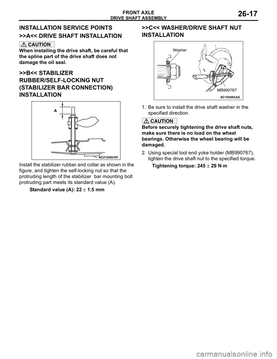
>>B<< STABILIZER
RUBBER/SELF-LOCKING NUT
(STABILIZER BAR CONNECTION)
INSTALLATION
Install the stabilizer rubber and collar as shown in the
figure, and tighten the self-locking nut so that the
protruding length of the stabilizer bar mounting bolt
protruding part meets its standard value (A).
Standard value (A): 22 ± 1.5 mm
>>C<< WASHER/DRIVE SHAFT NUT
INSTALLATION
1. Be sure to install the drive shaft washer in the
specified direction.
CAUTION
Before securely tightening the drive shaft nuts,
make sure there is no load on the wheel
bearings. Otherwise the wheel bearing will be
damaged.
2. Using special tool end yoke holder (MB990767),
tighten the drive shaft nut to the specified torque.
Tightening torque: 245 ± 29 N⋅m
AC210393AC
A
AC102465AD
MB990767 Washer
Page 173 of 788
SERVICE SPECIFICATION
POWER PLANT MOUNT32-3
SERVICE SPECIFICATION
M1321000300333
SPECIAL TOOL
M1321000600378
ItemStandard value
Protruding length of stabilizer link thread part mm 22 ± 1.5
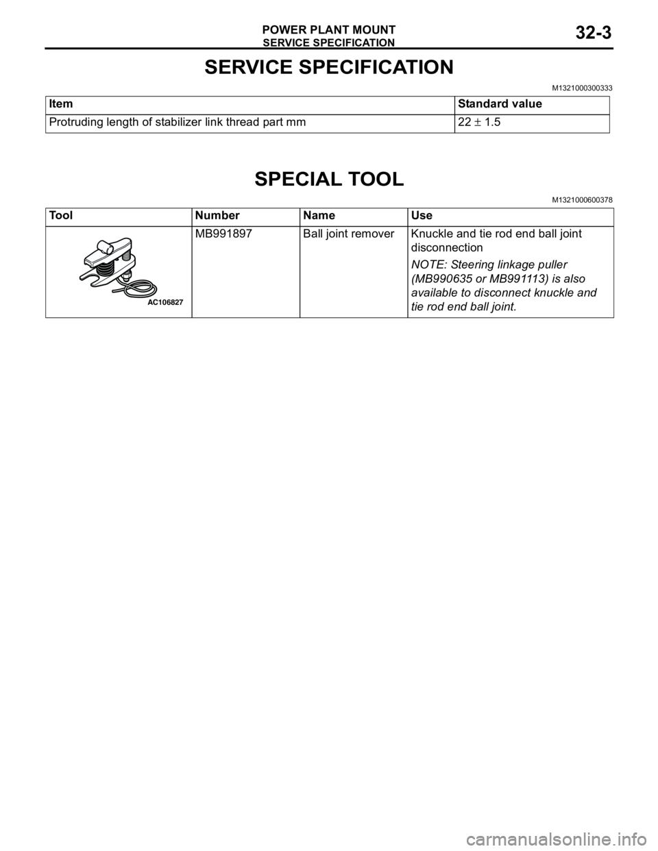
Tool Number Name Use
MB991897 Ball joint remover Knuckle and tie rod end ball joint
disconnection
NOTE: Steering linkage puller
(MB990635 or MB991113) is also
available to disconnect knuckle and
tie rod end ball joint.
AC106827
Page 181 of 788
