front MITSUBISHI LANCER 2005 Workshop Manual
[x] Cancel search | Manufacturer: MITSUBISHI, Model Year: 2005, Model line: LANCER, Model: MITSUBISHI LANCER 2005Pages: 788, PDF Size: 45.98 MB
Page 546 of 788
TROUBLESHOOTING
HEATER, AIR CONDITIONER AND VENTILATION55-62
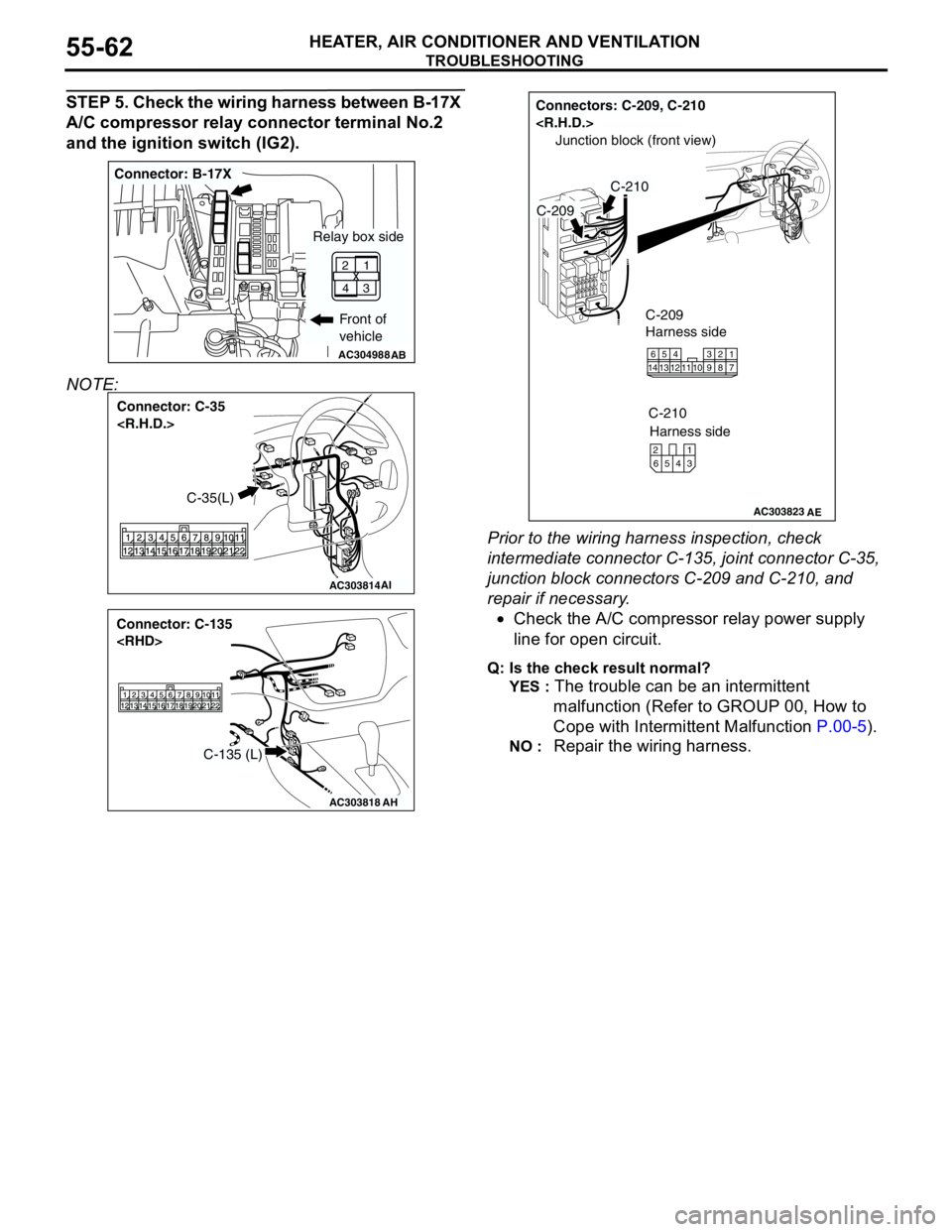
STEP 5. Check the wiring harness between B-17X
A/C compressor relay connector terminal No.2
and the ignition switch (IG2).
NOTE:
Prior to the wiring harness inspection, check
intermediate connector C-135, joint connector C-35,
junction block connectors C-209 and C-210, and
repair if necessary.
•Check the A/C compressor relay power supply
line for open circuit.
Q: Is the check result normal?
YES :
The trouble can be an intermittent
malfunction (Refer to GROUP 00, How to
Cope with Intermittent Malfunction P.00-5).
NO : Repair the wiring harness.
AC304988AB
Connector: B-17X
Front of
vehicle
1
3 2
4
Relay box side
AC303814
Connector: C-35
AI
C-35(L)
AC303818
Connector: C-135
AH
C-135 (L)
AC303823
Connectors: C-209, C-210
AE
C-210
Junction block (front view)
C-209
C-209
Harness side
1016
145
12134117 238 9
C-210
Harness side
4 65321
Page 547 of 788
TROUBLESHOOTING
HEATER, AIR CONDITIONER AND VENTILATION55-63
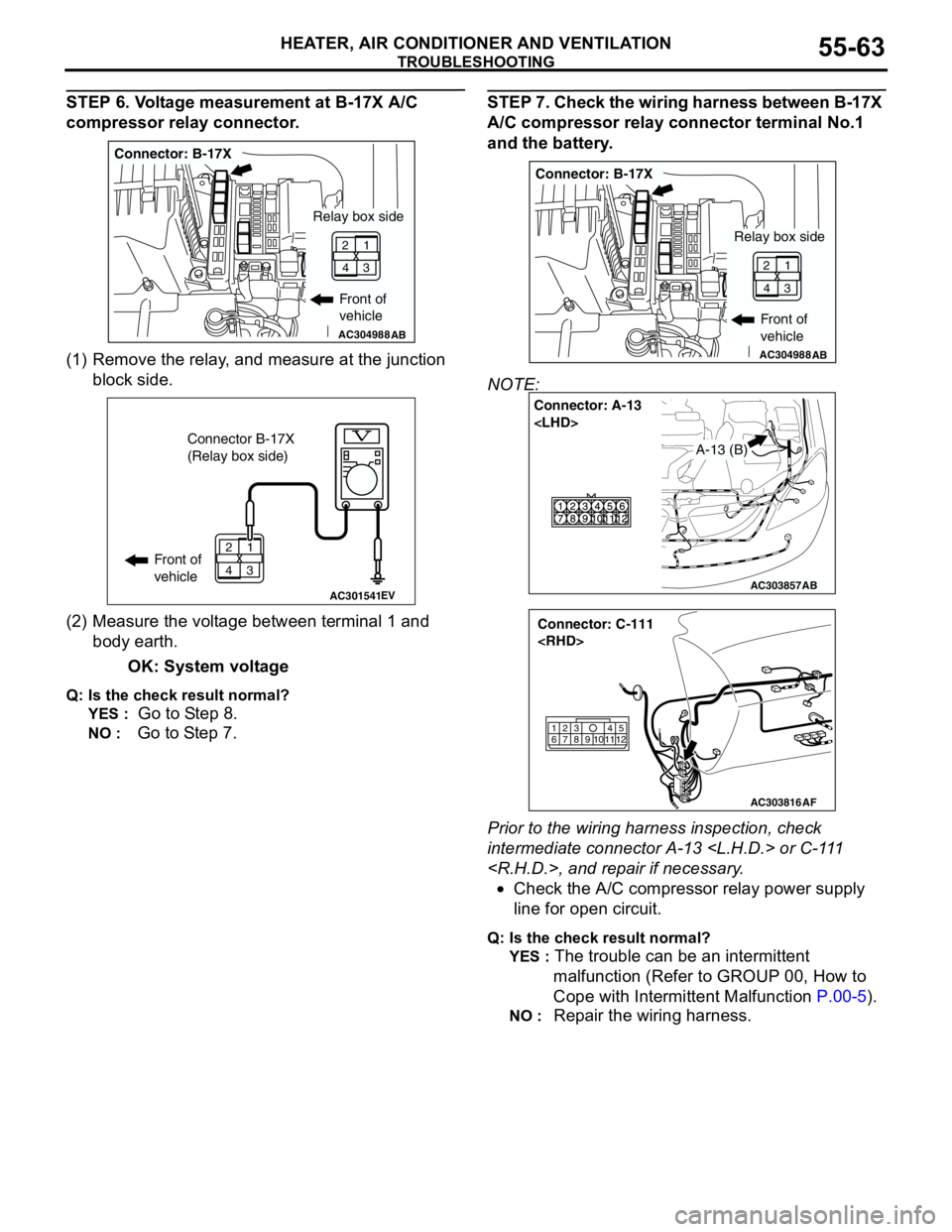
STEP 6. Voltage measurement at B-17X A/C
compressor relay connector.
(1) Remove the relay, and measure at the junction
block side.
(2) Measure the voltage between terminal 1 and
body earth.
OK: System voltage
Q: Is the check result normal?
YES :
Go to Step 8.
NO : Go to Step 7.
STEP 7. Check the wiring harness between B-17X
A/C compressor relay connector terminal No.1
and the battery.
NOTE:
Prior to the wiring harness inspection, check
intermediate connector A-13
•Check the A/C compressor relay power supply
line for open circuit.
Q: Is the check result normal?
YES :
The trouble can be an intermittent
malfunction (Refer to GROUP 00, How to
Cope with Intermittent Malfunction P.00-5).
NO : Repair the wiring harness.
AC304988AB
Connector: B-17X
Front of
vehicle
1
3 2
4
Relay box side
AC301541EV
Connector B-17X
(Relay box side)
Front of
vehicle1
3 2
4
AC304988AB
Connector: B-17X
Front of
vehicle
1
3 2
4
Relay box side
AC303857
Connector: A-13
AB
A-13 (B)
AC303816
Connector: C-111
AF
615
121179
810234
Page 548 of 788
TROUBLESHOOTING
HEATER, AIR CONDITIONER AND VENTILATION55-64
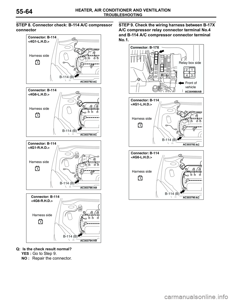
STEP 8. Connector check: B-114 A/C compressor
connector
Q: Is the check result normal?
YES :
Go to Step 9.
NO : Repair the connector.
STEP 9. Check the wiring harness between B-17X
A/C compressor relay connector terminal No.4
and B-114 A/C compressor connector terminal
No.1.
AC303782
Connector: B-114
<4G1-L.H.D.>
AC
Harness side
B-114 (B)
AC303790
Connector: B-114
<4G6-L.H.D.>
AC
Harness side
B-114 (B)
AC303786
Connector: B-114
<4G1-R.H.D.>
AB
Harness side
B-114 (B)
AC303794
Connector: B-114
<4G6-R.H.D.>
AB
Harness side
B-114 (B)
AC304988AB
Connector: B-17X
Front of
vehicle
1
3 2
4
Relay box side
AC303782
Connector: B-114
<4G1-L.H.D.>
AC
Harness side
B-114 (B)
AC303790
Connector: B-114
<4G6-L.H.D.>
AC
Harness side
B-114 (B)
Page 550 of 788
TROUBLESHOOTING
HEATER, AIR CONDITIONER AND VENTILATION55-66
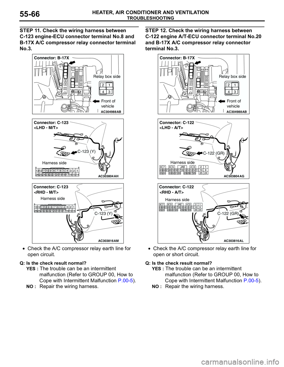
STEP 11. Check the wiring harness between
C-123 engine-ECU connector terminal No.8 and
B-17X A/C compressor relay connector terminal
No.3.
•Check the A/C compressor relay earth line for
open circuit.
Q: Is the check result normal?
YES :
The trouble can be an intermittent
malfunction (Refer to GROUP 00, How to
Cope with Intermittent Malfunction P.00-5).
NO : Repair the wiring harness.
STEP 12. Check the wiring harness between
C-122 engine A/T-ECU connector terminal No.20
and B-17X A/C compressor relay connector
terminal No.3.
•Check the A/C compressor relay earth line for
open or short circuit.
Q: Is the check result normal?
YES :
The trouble can be an intermittent
malfunction (Refer to GROUP 00, How to
Cope with Intermittent Malfunction P.00-5).
NO : Repair the wiring harness.
AC304988AB
Connector: B-17X
Front of
vehicle
1
3 2
4
Relay box side
AC303804
Connector: C-123
AH
Harness side
C-123 (Y)
AC303816
Connector: C-123
AM
Harness side
C-123 (Y)
AC304988AB
Connector: B-17X
Front of
vehicle
1
3 2
4
Relay box side
AC303804
Connector: C-122
AG
Harness side
C-122 (GR)
AC303816
Connector: C-122
AL
Harness side
C-122 (GR)
Page 558 of 788
ON-VEHICLE SERVICE
HEATER, AIR CONDITIONER AND VENTILATION55-74
REFRIGERANT LEAK REPAIR
PROCEDURE
M1552001500277
LOST CHARGE
If the system has lost all charge due to a leak:
1. Evacuate the system (Refer to P.55-72).
2. Charge the system with approximately 480 − 520
g of refrigerant.
3. Check for leaks.
4. Discharge the system.
5. Repair leaks.
CAUTION
Replacement filter-drier units must be sealed
while in storage. The drier used in these units will
saturate water quickly upon exposure to the
atmosphere. When installing a drier, have all
tools and supplies ready for quick assembly to
avoid keeping the system open any longer than
necessary.
6. Replace receiver drier.
7. Evacuate and charge system.
LOW CHARGE
If the system has not lost all of its refrigerant charge;
locate and repair all leaks. If it is necessary to
increase the system pressure to find the leak
(because of an especially low charge) add
refrigerant. If it is possible to repair the leak without
discharging the refrigerant system, use the
procedure for correcting low refrigerant level.
HANDLING TUBING AND FITTINGS
Kinks in the refrigerant tubing or sharp bends in the
refrigerant hose lines will greatly reduce the capacity
of the entire system. High pressures are produced in
the system when it is operating. Extreme care must
be exercised to make sure that all connections are
pressure tight. Dirt and moisture can enter the
system when it is opened for repair or replacement of
lines or components. The following precautions must
be observed. The system must be completely
discharged before opening any fitting of connection
in the refrigeration system. Open fittings with caution
even after the system has been discharged. If any
pressure is noticed as a fitting is loosened, allow
trapped pressure to bleed off very slowly.
Never attempt to rebend formed lines to fit. Use the
correct line for the installation you are servicing. A
good rule for the flexible hose lines is keep the radius
of all bends at least 10 times the diameter of the
hose.Sharper bends will reduce the flow of refrigerant. The
flexible hose lines should be routed so that they are
at least 80 mm from the exhaust manifold. It is good
practice to inspect all flexible hose lines at least once
a year to make sure they are in good condition and
properly routed.
On standard plumbing fittings with O-rings, these
O-rings are not reusable.
COMPRESSOR NOISE CHECKM1552008700272
You must first know the conditions when the noise
occurs. These conditions are: weather, vehicle
speed, in gear or neutral, engine temperature or any
other special conditions.
Noises that develop during A/C operation can often
be misleading. For example: what sounds like a
failed front bearing or connecting rod, may be
caused by loose bolts, nuts, mounting brackets, or a
loose clutch assembly. Verify accessory drive belt
tension (power steering or alternator).
Improper accessory drive belt tension can cause a
misleading noise when the compressor is engaged
and little or no noise when the compressor is
disengaged.
Drive belts are speed-sensitive. That is, at different
engine speeds, and depending upon belt tension,
belts can develop unusual noises that are often
mistaken for mechanical problems within the
compressor.
ADJUSTMENT
1. Select a quiet area for testing. Duplicate
conditions as much as possible. Switch the
compressor on and off several times to clearly
identify compressor noise. To duplicate high
ambient conditions (high head pressure), restrict
air flow through the condenser. Install a manifold
gauge set to make sure discharge pressure
doesn't exceed 2,070 kPa.
2. Tighten all compressor mounting bolts, clutch
mounting bolt, and compressor drive belt. Check
to assure clutch coil is tight (no rotation or
wobble).
3. Check refrigerant hoses for rubbing or
interference that can cause unusual noises.
4. Check refrigerant charge (Refer to P.55-69).
5. Recheck compressor noise as in Step 1.
6. If noise still exists, loosen compressor mounting
bolts and retighten. Repeat Step 1.
7. If noise continues, replace compressor and repeat
Step 1.
Page 559 of 788
ON-VEHICLE SERVICE
HEATER, AIR CONDITIONER AND VENTILATION55-75
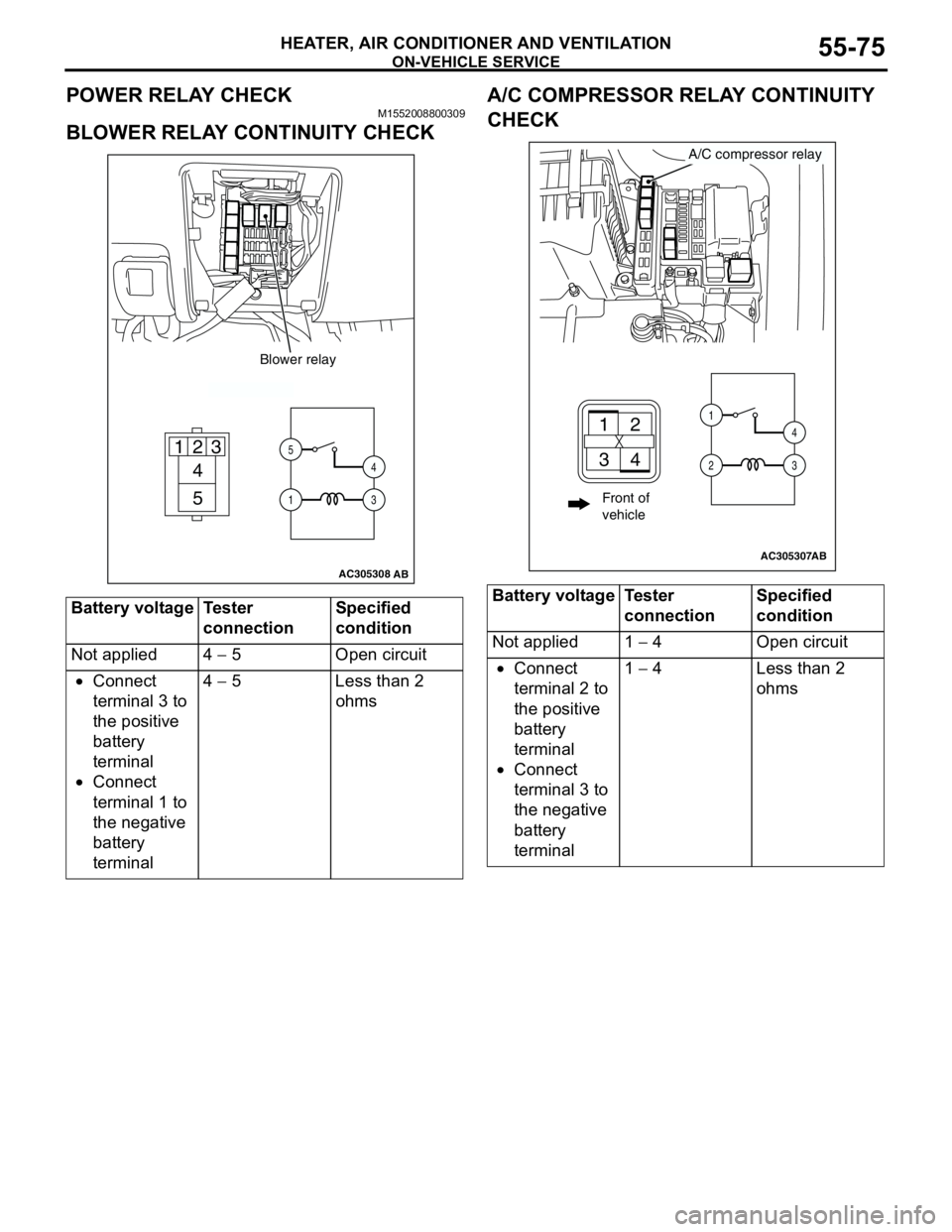
POWER RELAY CHECKM1552008800309
BLOWER RELAY CONTINUITY CHECKA/C COMPRESSOR RELAY CONTINUITY
CHECK
Battery voltage Tester
connectionSpecified
condition
Not applied 4 − 5 Open circuit
•Connect
terminal 3 to
the positive
battery
terminal
•Connect
terminal 1 to
the negative
battery
terminal4 − 5 Less than 2
ohms
AC305308
4
5 1
235
14
3
Blower relay
AB
Battery voltage Tester
connectionSpecified
condition
Not applied 1 − 4 Open circuit
•Connect
terminal 2 to
the positive
battery
terminal
•Connect
terminal 3 to
the negative
battery
terminal1 − 4 Less than 2
ohms
AC305307
A/C compressor relay
AB
21
34
1
24
3
Front of
vehicle
Page 565 of 788
HEATER UNIT, HEATER CORE, BLOWER ASSEMBLY AND EVAPORATOR UNIT
HEATER, AIR CONDITIONER AND VENTILATION55-81
HEATER UNIT, HEATER CORE, BLOWER ASSEMBLY
AND EVAPORATOR UNIT
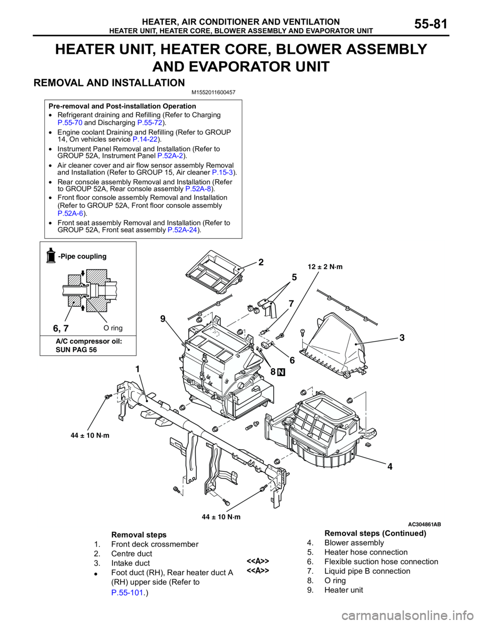
REMOVAL AND INSTALLATION
M1552011600457
Pre-removal and Post-installation Operation
•Refrigerant draining and Refilling (Refer to Charging
P.55-70 and Discharging P.55-72).
•Engine coolant Draining and Refilling (Refer to GROUP
14, On vehicles service P.14-22).
•Instrument Panel Removal and Installation (Refer to
GROUP 52A, Instrument Panel P.52A-2).
•Air cleaner cover and air flow sensor assembly Removal
and Installation (Refer to GROUP 15, Air cleaner P.15-3).
•Rear console assembly Removal and Installation (Refer
to GROUP 52A, Rear console assembly P.52A-8).
•Front floor console assembly Removal and Installation
(Refer to GROUP 52A, Front floor console assembly
P.52A-6).
•Front seat assembly Removal and Installation (Refer to
GROUP 52A, Front seat assembly P.52A-24).
AC304861
1
2
3
4 5
6
7
8
N
9
AB
12 ± 2 N·m
6, 7O ring -Pipe coupling
A/C compressor oil:
SUN PAG 56
44 ± 10 N·m
44 ± 10 N·m
Removal steps
1. Front deck crossmember
2. Centre duct
3. Intake duct
•Foot duct (RH), Rear heater duct A
(RH) upper side (Refer to
P.55-101.)4. Blower assembly
5. Heater hose connection
<>6. Flexible suction hose connection
<>7. Liquid pipe B connection
8. O ring
9. Heater unitRemoval steps (Continued)
Page 569 of 788
BLOWERMOTOR, RESISTOR AND OUTSIDE/ INSIDE AIR SELECTION DAMPER CONTROL MOTOR
HEATER, AIR CONDITIONER AND VENTILATION55-85
BLOWERMOTOR, RESISTOR AND OUTSIDE/
INSIDE AIR SELECTION DAMPER CONTROL MOTOR
REMOVAL AND INSTALLATION
M1551002800320
AC304885AB
2
31
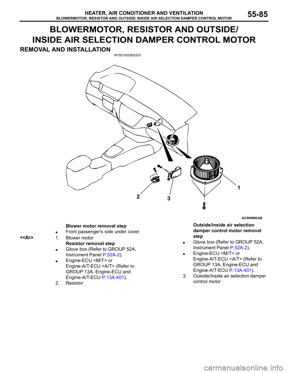
Blower motor removal step
•Front passenger's side under cover
<>1. Blower motor
Resistor removal step
•Glove box (Refer to GROUP 52A,
Instrument Panel P.52A-2).
•Engine-ECU
Engine-A/T-ECU (Refer to
GROUP 13A, Engine-ECU and
Engine-A/T-ECU P.13A-401).
2. ResistorOutside/inside air selection
damper control motor removal
step
•Glove box (Refer to GROUP 52A,
Instrument Panel P.52A-2).
•Engine-ECU
Engine-A/T-ECU (Refer to
GROUP 13A, Engine-ECU and
Engine-A/T-ECU P.13A-401).
3. Outside/inside air selection damper
control motor
Page 582 of 788
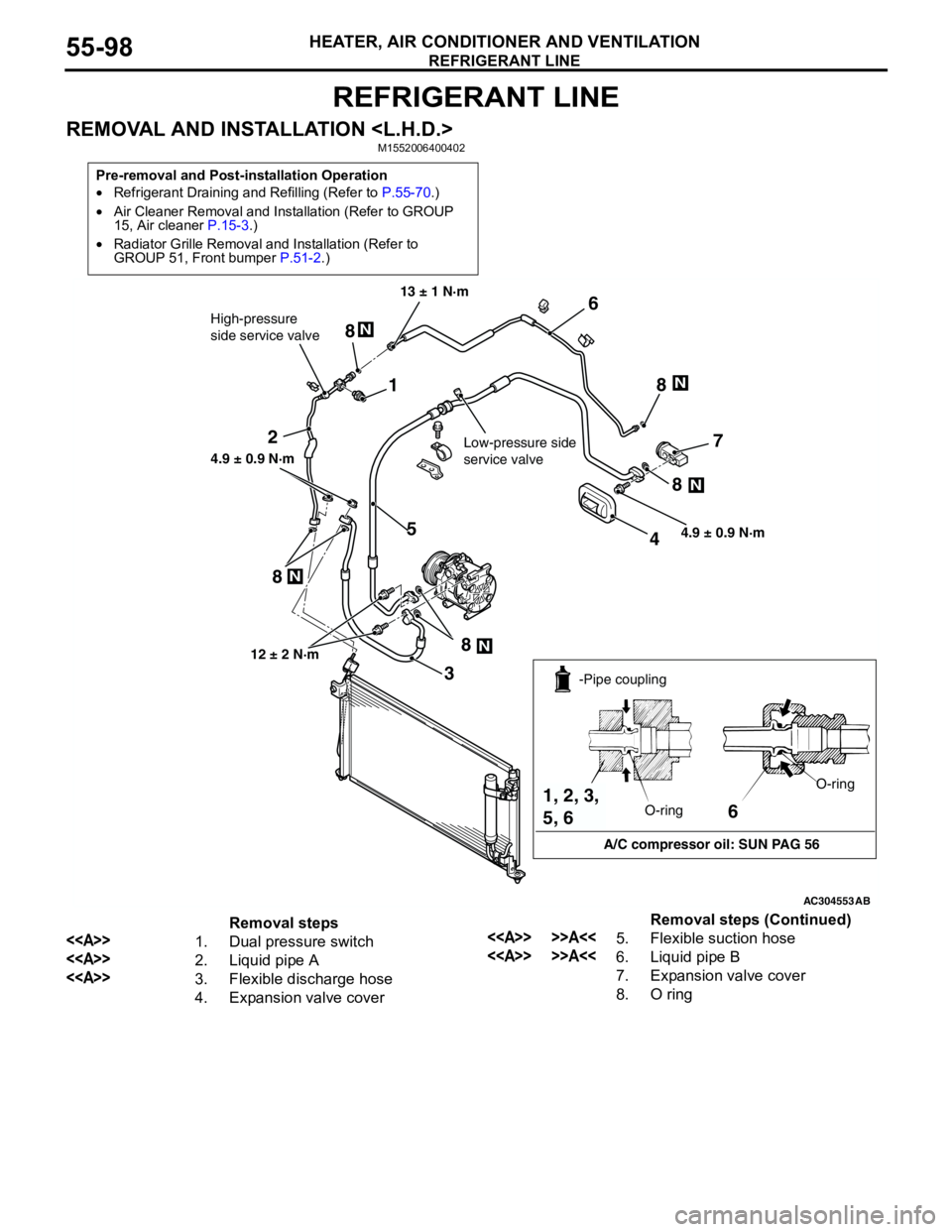
REFRIGERANT LINE
HEATER, AIR CONDITIONER AND VENTILATION55-98
REFRIGERANT LINE
REMOVAL AND INSTALLATION
Pre-removal and Post-installation Operation
•Refrigerant Draining and Refilling (Refer to P.55-70.)
•Air Cleaner Removal and Installation (Refer to GROUP
15, Air cleaner P.15-3.)
•Radiator Grille Removal and Installation (Refer to
GROUP 51, Front bumper P.51-2.)
AC304553
1
2
3
45
6
7
8N
N
N
N
N
8 8
8
8
High-pressure
side service valve
Low-pressure side
service valve
4.9 ± 0.9 N·m 13 ± 1 N·m
4.9 ± 0.9 N·m
12 ± 2 N·m
AB
6
A/C compressor oil: SUN PAG 56 -Pipe coupling
O-ringO-ring
1, 2, 3,
5, 6
Removal steps
<>1. Dual pressure switch
<>2. Liquid pipe A
<>3. Flexible discharge hose
4. Expansion valve cover
<> >>A<<5. Flexible suction hose
<> >>A<<6. Liquid pipe B
7. Expansion valve cover
8. O ringRemoval steps (Continued)
Page 583 of 788
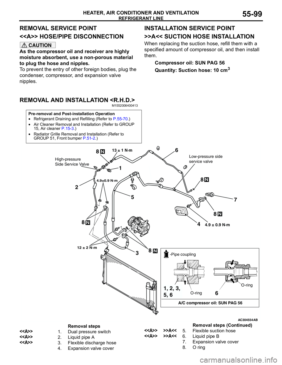
REFRIGERANT LINE
HEATER, AIR CONDITIONER AND VENTILATION55-99
REMOVAL SERVICE POINT
<> HOSE/PIPE DISCONNECTION
CAUTION
As the compressor oil and receiver are highly
moisture absorbent, use a non-porous material
to plug the hose and nipples.
To prevent the entry of other foreign bodies, plug the
condenser, compressor, and expansion valve
nipples.
INSTALLATION SERVICE POINT
>>A<< SUCTION HOSE INSTALLATION
When replacing the suction hose, refill them with a
specified amount of compressor oil, and then install
them.
Compressor oil: SUN PAG 56
Quantity: Suction hose: 10 cm
3
REMOVAL AND INSTALLATION
Pre-removal and Post-installation Operation
•Refrigerant Draining and Refilling (Refer to P.55-70.)
•Air Cleaner Removal and Installation (Refer to GROUP
15, Air cleaner P.15-3.)
•Radiator Grille Removal and Installation (Refer to
GROUP 51, Front bumper P.51-2.)
AC304554
1
2
3
4
5
6
7
8N
8N
8N
N8 8
N
4.9±0.9 N·m
Low-pressure side
service valve 13 ± 1 N·mHigh-pressure
Side Service Valve
12 ± 2 N·m
4.9 ± 0.9 N·m
AB
6
A/C compressor oil: SUN PAG 56 -Pipe coupling
O-ringO-ring
1, 2, 3,
5, 6
Removal steps
<>1. Dual pressure switch
<>2. Liquid pipe A
<>3. Flexible discharge hose
4. Expansion valve cover
<> >>A<<5. Flexible suction hose
<> >>A<<6. Liquid pipe B
7. Expansion valve cover
8. O ringRemoval steps (Continued)