battery location MITSUBISHI LANCER 2005 Workshop Manual
[x] Cancel search | Manufacturer: MITSUBISHI, Model Year: 2005, Model line: LANCER, Model: MITSUBISHI LANCER 2005Pages: 788, PDF Size: 45.98 MB
Page 118 of 788
EMISSION CONTROL
ENGINE AND EMISSION CONTROL17-10
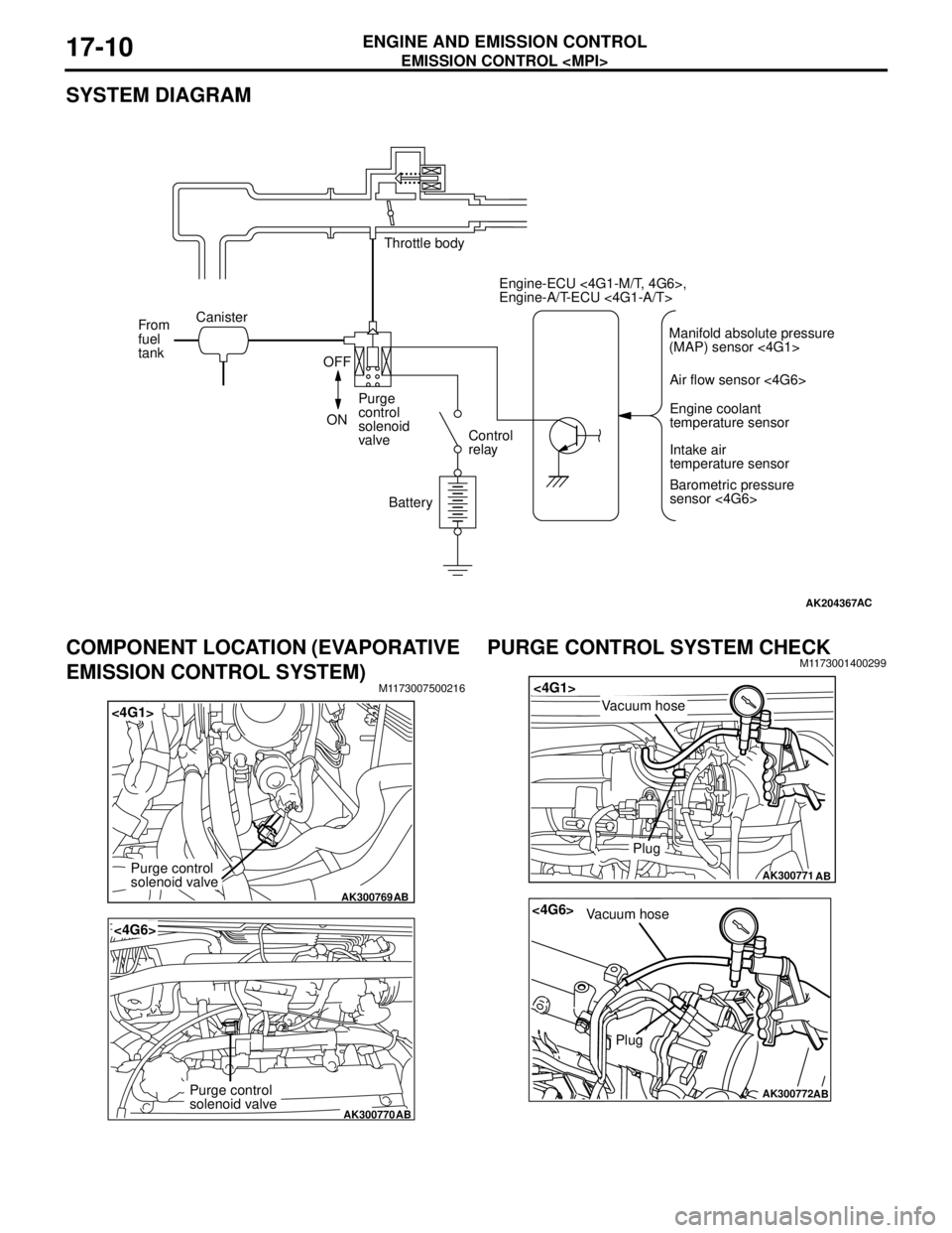
SYSTEM DIAGRAM
COMPONENT LOCATION (EVAPORATIVE
EMISSION CONTROL SYSTEM)
M1173007500216
PURGE CONTROL SYSTEM CHECKM1173001400299
AK204367AC
Throttle body
Canister
From
fuel
tank
OFF
ONPurge
control
solenoid
valveControl
relay
BatteryEngine-ECU <4G1-M/T, 4G6>,
Engine-A/T-ECU <4G1-A/T>
Air flow sensor <4G6>
Engine coolant
temperature sensor
Intake air
temperature sensor
Barometric pressure
sensor <4G6> Manifold absolute pressure
(MAP) sensor <4G1>
AK300769
<4G1>
AB
Purge control
solenoid valve
AK300770
<4G6>
AB
Purge control
solenoid valve
AK300771
<4G1>
AB
Plug
Vacuum hose
AK300772
<4G6>
AB
Plug
Vacuum hose
Page 122 of 788
EMISSION CONTROL
ENGINE AND EMISSION CONTROL17-14
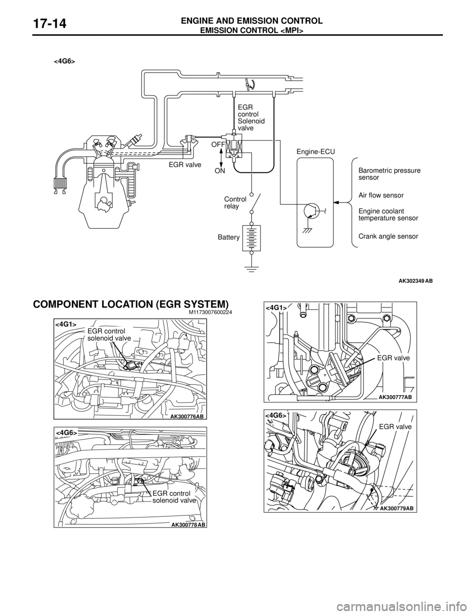
COMPONENT LOCATION (EGR SYSTEM)M1173007600224
AK302349AB
<4G6>
EGR
control
Solenoid
valve
EGR valveOFF
ON
Control
relay
BatteryEngine-ECU
Barometric pressure
sensor
Air flow sensor
Engine coolant
temperature sensor
Crank angle sensor
AK300776
<4G1>
AB
EGR control
solenoid valve
AK300778
<4G6>
AB
EGR control
solenoid valve
AK300777
<4G1>
AB
EGR valve
AK300779AB
<4G6>
EGR valve
Page 392 of 788
BATTERY
CHASSIS ELECTRICAL54A-4
BATTERY
SERVICE SPECIFICATIONSM1541000300209
ON-VEHICLE SERVICE
FLUID LEVEL AND SPECIFIC GRAVITY
CHECK
M1541001000438
CAUTION
•If the battery fluid is below the LOWER
LEVEL, the battery could explode in using.
•If the battery fluid is over the UPPER LEVEL,
leakage could result.
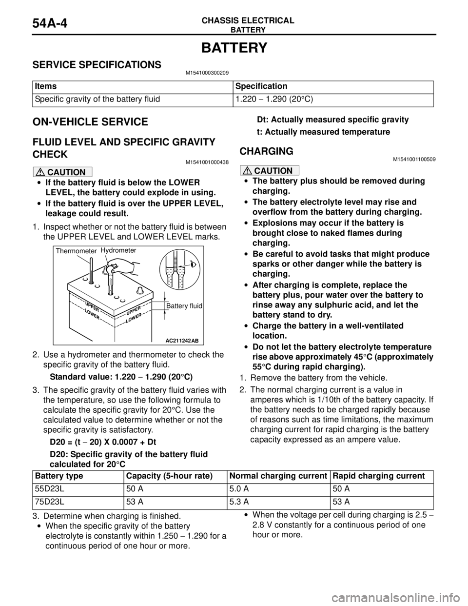
1. Inspect whether or not the battery fluid is between
the UPPER LEVEL and LOWER LEVEL marks.
2. Use a hydrometer and thermometer to check the
specific gravity of the battery fluid.
Standard value: 1.220 − 1.290 (20°C)
3. The specific gravity of the battery fluid varies with
the temperature, so use the following formula to
calculate the specific gravity for 20°C. Use the
calculated value to determine whether or not the
specific gravity is satisfactory.
D20 = (t − 20) X 0.0007 + Dt
D20: Specific gravity of the battery fluid
calculated for 20°CDt: Actually measured specific gravity
t: Actually measured temperature
CHARGINGM1541001100509
CAUTION
•The battery plus should be removed during
charging.
•The battery electrolyte level may rise and
overflow from the battery during charging.
•Explosions may occur if the battery is
brought close to naked flames during
charging.
•Be careful to avoid tasks that might produce
sparks or other danger while the battery is
charging.
•After charging is complete, replace the
battery plus, pour water over the battery to
rinse away any sulphuric acid, and let the
battery stand to dry.
•Charge the battery in a well-ventilated
location.
•Do not let the battery electrolyte temperature
rise above approximately 45°C (approximately
55°C during rapid charging).
1. Remove the battery from the vehicle.
2. The normal charging current is a value in
amperes which is 1/10th of the battery capacity. If
the battery needs to be charged rapidly because
of reasons such as time limitations, the maximum
charging current for rapid charging is the battery
capacity expressed as an ampere value.
3. Determine when charging is finished.
•When the specific gravity of the battery
electrolyte is constantly within 1.250 − 1.290 for a
continuous period of one hour or more.•When the voltage per cell during charging is 2.5 −
2.8 V constantly for a continuous period of one
hour or more. Items Specification
Specific gravity of the battery fluid 1.220 − 1.290 (20°C)
AC211242AB
Battery fluid ThermometerHydrometer
Battery type Capacity (5-hour rate) Normal charging current Rapid charging current
55D23L 50 A 5.0 A 50 A
75D23L 53 A 5.3 A 53 A
Page 455 of 788
HEADLAMP
CHASSIS ELECTRICAL54A-67
NOTE: Height from the floor to the centre of
the headlamps (Reference value): 840 mm
(3) Measure the distance from the centre line of
the vehicle to the centre of each headlamp.
Transfer the measurement to the screen.
Vertical tape or mark on the screen with
reference to the centre line of each headlamp
bulb.
HEADLAMP ADJUSTMENT
CAUTION
•Do not cover a headlamp for more than three
minutes to prevent the plastic headlamp lens
deformation.
•When adjusting one headlamp beam, make
sure that another headlamp is off by
disconnecting the connector from it. When
reconnecting the connector, make sure that
the headlamp beam is not disturbed
accidentally.
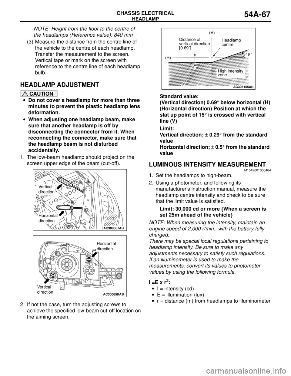
1. The low-beam headlamp should project on the
screen upper edge of the beam (cut-off).
2. If not the case, turn the adjusting screws to
achieve the specified low-beam cut-off location on
the aiming screen.Standard value:
(Vertical direction) 0.69° below horizontal (H)
(Horizontal direction) Position at which the
stat up point of 15° is crossed with vertical
line (V)
Limit:
Vertical direction; ± 0.29° from the standard
value
Horizontal direction; ± 0.5° from the standard
value
LUMINOUS INTENSITY MEASUREMENTM1542001000464
1. Set the headlamps to high-beam.
2. Using a photometer, and following its
manufacturer's instruction manual, measure the
headlamp centre intensity and check to be sure
that the limit value is satisfied.
Limit: 30,000 cd or more {When a screen is
set 25m ahead of the vehicle}
NOTE: When measuring the intensity, maintain an
engine speed of 2,000 r/min., with the battery fully
charged.
There may be special local regulations pertaining to
headlamp intensity. Be sure to make any
adjustments necessary to satisfy such regulations.
If an illuminometer is used to make the
measurements, convert its values to photometer
values by using the following formula.
I =E x r
2:
•I = intensity (cd)
•E = illumination (lux)
•r = distance (m) from headlamps to illuminometer
AC300567AB
Vertical
direction
Horizontal
direction
AC300658AB
Vertical
direction
Horizontal
direction
AC305155
(H)(V)
Distance of
vertical direction
[0.69˚]Headlamp
centre
High intensity
zone
15˚
AB
Page 589 of 788
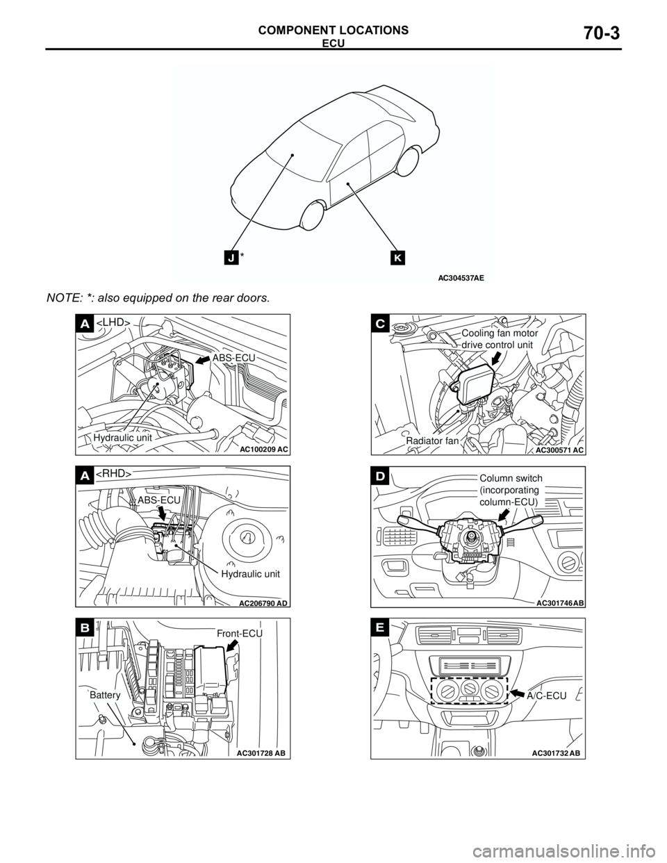
ECU
COMPONENT LOCATIONS70-3
NOTE: *: also equipped on the rear doors.
AC304537
JK*
AE
AC100209AC
A
ABS-ECU
Hydraulic unit
AC206790
A
AD
ABS-ECU
Hydraulic unit
AC301728AB
BFront-ECU
Battery
AC300571
C
ACRadiator fan
Cooling fan motor
drive control unit
AC301746
DColumn switch
(incorporating
column-ECU)
AB
AC301732AB
E
A/C-ECU
Page 596 of 788
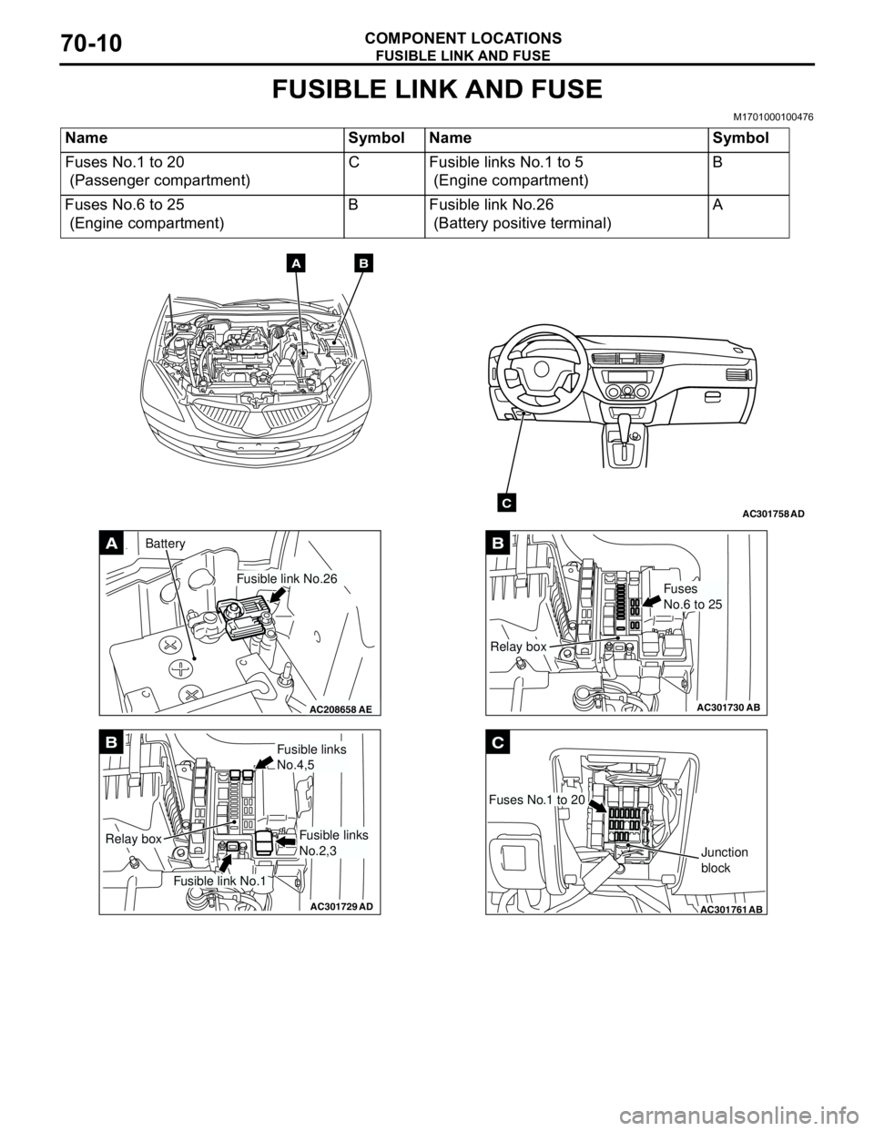
FUSIBLE LINK AND FUSE
COMPONENT LOCATIONS70-10
FUSIBLE LINK AND FUSE
M1701000100476
Name Symbol Name Symbol
Fuses No.1 to 20
(Passenger compartment)C Fusible links No.1 to 5
(Engine compartment)B
Fuses No.6 to 25
(Engine compartment)B Fusible link No.26
(Battery positive terminal)A
AC301758AD
AB
C
AC208658AE
A
Fusible link No.26
Battery
AC301729AD
B
Fusible link No.1
Relay box
Fusible links
No.4,5
Fusible links
No.2,3
AC301730
B
AB
Fuses
No.6 to 25
Relay box
AC301761
C
AB
Fuses No.1 to 20
Junction
block