front MITSUBISHI LANCER 2005 Workshop Manual
[x] Cancel search | Manufacturer: MITSUBISHI, Model Year: 2005, Model line: LANCER, Model: MITSUBISHI LANCER 2005Pages: 788, PDF Size: 45.98 MB
Page 482 of 788
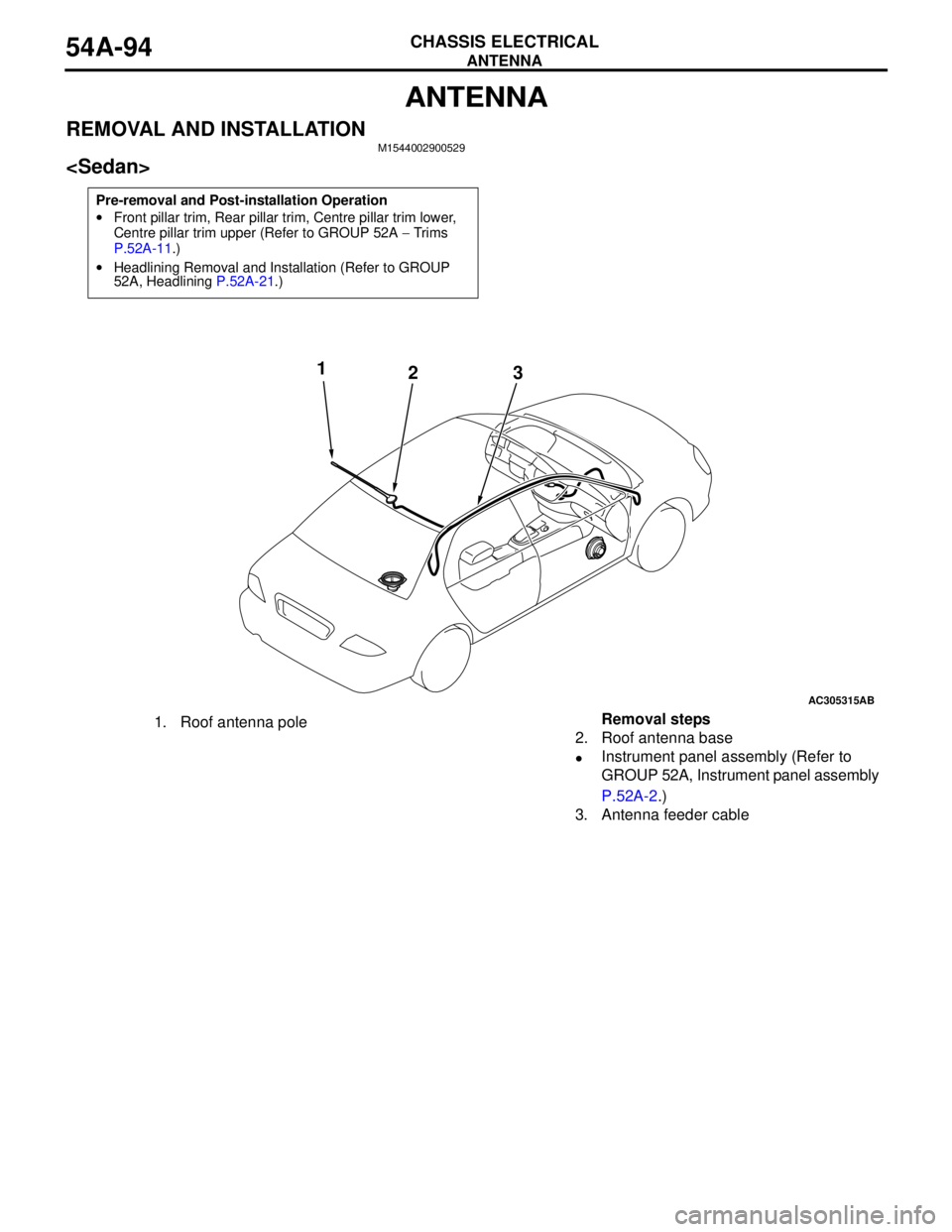
ANTENNA
CHASSIS ELECTRICAL54A-94
ANTENNA
REMOVAL AND INSTALLATIONM1544002900529
Pre-removal and Post-installation Operation
•Front pillar trim, Rear pillar trim, Centre pillar trim lower,
Centre pillar trim upper (Refer to GROUP 52A − Trims
P.52A-11.)
•Headlining Removal and Installation (Refer to GROUP
52A, Headlining P.52A-21.)
AC305315AB
1
23
1. Roof antenna poleRemoval steps
2. Roof antenna base
•Instrument panel assembly (Refer to
GROUP 52A, Instrument panel assembly
P.52A-2.)
3. Antenna feeder cable
Page 483 of 788
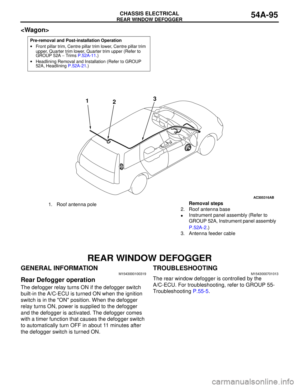
REAR WINDOW DEFOGGER
CHASSIS ELECTRICAL54A-95
REAR WINDOW DEFOGGER
GENERAL INFORMATIONM1543000100319
Rear Defogger operation
The defogger relay turns ON if the defogger switch
built-in the A/C-ECU is turned ON when the ignition
switch is in the "ON" position. When the defogger
relay turns ON, power is supplied to the defogger
and the defogger is activated. The defogger comes
with a timer function that causes the defogger switch
to automatically turn OFF in about 11 minutes after
the defogger switch is turned ON.
TROUBLESHOOTINGM1543000701013
The rear window defogger is controlled by the
A/C-ECU. For troubleshooting, refer to GROUP 55-
Troubleshooting P.55-5.
Pre-removal and Post-installation Operation
•Front pillar trim, Centre pillar trim lower, Centre pillar trim
upper, Quarter trim lower, Quarter trim upper (Refer to
GROUP 52A − Trims P.52A-11.)
•Headlining Removal and Installation (Refer to GROUP
52A, Headlining P.52A-21.)
AC305316
AB
1
23
1. Roof antenna poleRemoval steps
2. Roof antenna base
•Instrument panel assembly (Refer to
GROUP 52A, Instrument panel assembly
P.52A-2.)
3. Antenna feeder cable
Page 485 of 788
55-1
GROUP 55
HEATER, AIR
CONDITIONER AND
VENTILATION
CONTENTS
SERVICE SPECIFICATIONS . . . . . . .55-3
LUBRICANTS . . . . . . . . . . . . . . . . . .55-3
SPECIAL TOOLS . . . . . . . . . . . . . . . .55-4
TROUBLESHOOTING . . . . . . . . . . . .55-5DIAGNOSIS TROUBLESHOOTING
FLOW . . . . . . . . . . . . . . . . . . . . . . . . . . . . . 55-5
SYMPTOM CHART . . . . . . . . . . . . . . . . . . . 55-5
SYMPTOM PROCEDURES . . . . . . . . . . . . 55-5
CHECK AT ECU TERMINAL
CHECK AT ECU TERMINAL
Continued on next page
W ARNING S RE GA RDING S E RV ICIN G O F SUP P LE MEN TAL R ES TRAI NT S Y ST EM (SRS ) E Q UIP PE D VE HICL ES
I mp roper se rvi ce o r m ai nte na nce of a ny c omp onent of the SRS , or an y SRS -re la te d c om pone nt, ca n le a d to
personal injury or death to service personnel (from inadvertent firing of the air bag) or to the driver (from
re nd er ing the S RS inop er ati ve).
S e rvic e or m ai nten anc e of an y SRS com pon ent or SRS -re late d com pone nt m ust be pe rfor me d only a t an
authorized MITSUBISHI dealer.
M ITSUBISHI dealer p erso nnel must thoroughly review th is man ual, and esp ecially its GROU P 52B - Su pplemen tal
Restraint System (SR S) b efore beginn ing an y service o r maintenance of any comp onent of th e SRS or any SRS-
rel ated com ponent.
NOTE
The SRS includes the following components: front impact sens ors , SRS-ECU, SRS warning lamp, air bag module, c lock spring
and interconnecting wiring. Other SRS-related components (that may have to be remov ed/installed in connection with SRS
service or maintenance) are indicated in the table of c ontents by an asterisk (*).
Page 492 of 788
TROUBLESHOOTING
HEATER, AIR CONDITIONER AND VENTILATION55-8
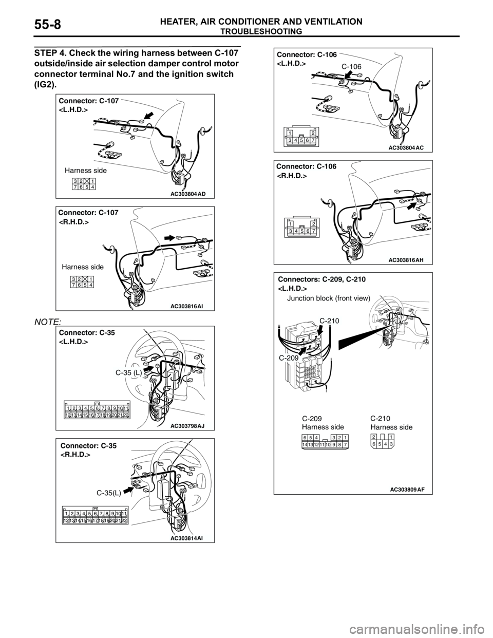
STEP 4. Check the wiring harness between C-107
outside/inside air selection damper control motor
connector terminal No.7 and the ignition switch
(IG2).
NOTE:
AC303804
Connector: C-107
AD
Harness side
AC303816
Connector: C-107
AI
Harness side
AC303798
Connector: C-35
AJ
2 1313 12 1421 105 4616 15 17789
19 18 2011
22
C-35 (L)
AC303814
Connector: C-35
AI
C-35(L)
AC303804
Connector: C-106
AC
C-106
AC303816
Connector: C-106
AH
AC303809
Connectors: C-209, C-210
AF
C-209
C-210
Junction block (front view)
C-209
Harness side
1016
145
12134117 238 9
C-210
Harness side
4 65321
Page 493 of 788
TROUBLESHOOTING
HEATER, AIR CONDITIONER AND VENTILATION55-9
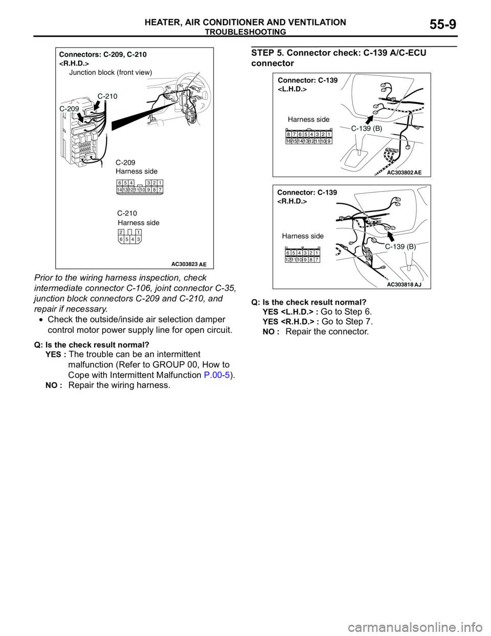
Prior to the wiring harness inspection, check
intermediate connector C-106, joint connector C-35,
junction block connectors C-209 and C-210, and
repair if necessary.
•Check the outside/inside air selection damper
control motor power supply line for open circuit.
Q: Is the check result normal?
YES :
The trouble can be an intermittent
malfunction (Refer to GROUP 00, How to
Cope with Intermittent Malfunction P.00-5).
NO : Repair the wiring harness.
STEP 5. Connector check: C-139 A/C-ECU
connector
Q: Is the check result normal?
YES
Go to Step 6.
YES
NO : Repair the connector.
AC303823
Connectors: C-209, C-210
AE
C-210
Junction block (front view)
C-209
C-209
Harness side
1016
145
12134117 238 9
C-210
Harness side
4 65321
AC303802
Connector: C-139
AE
C-139 (B)
Harness side
AC303818
Connector: C-139
AJ
Harness side
C-139 (B)
11 12657 8 9 103 421
Page 516 of 788
TROUBLESHOOTING
HEATER, AIR CONDITIONER AND VENTILATION55-32
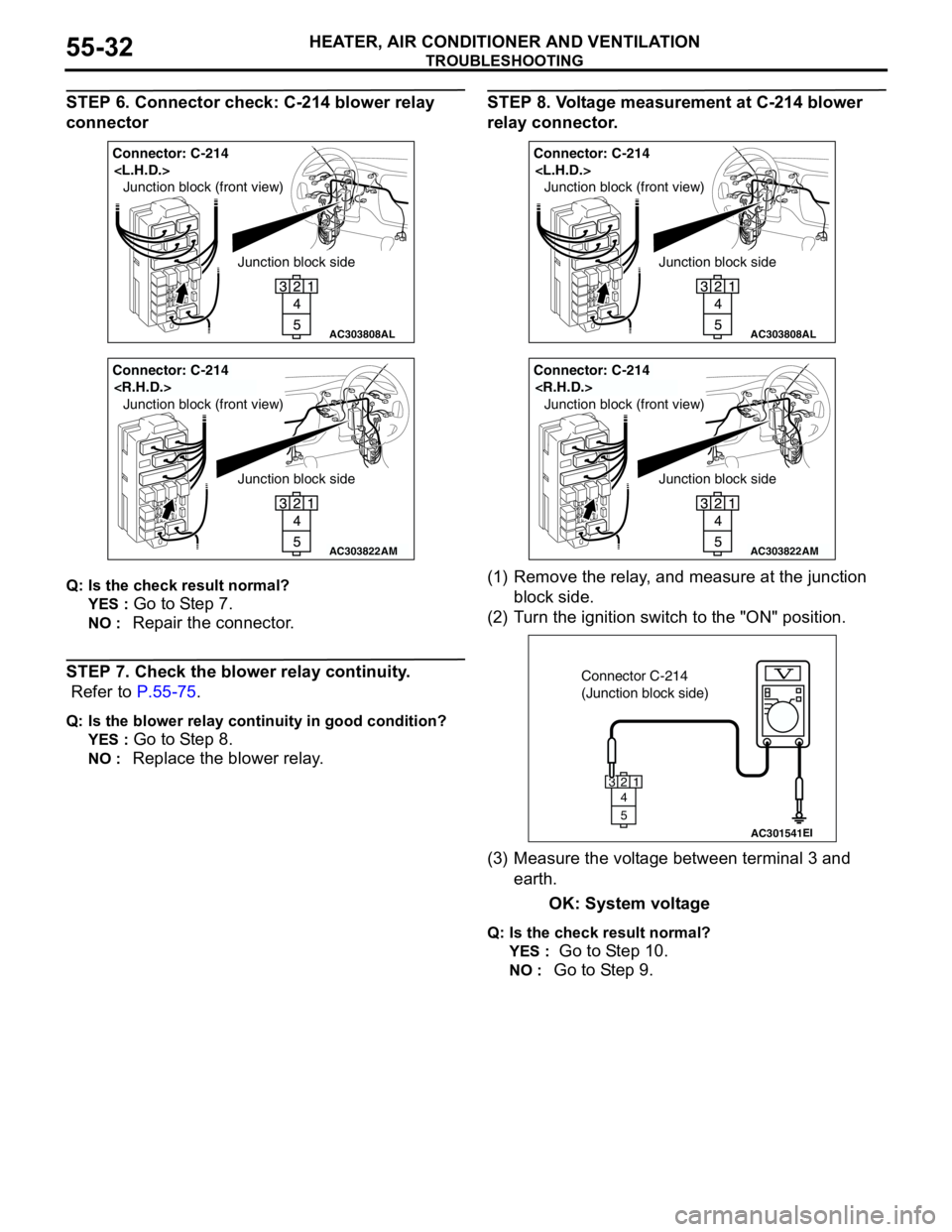
STEP 6. Connector check: C-214 blower relay
connector
Q: Is the check result normal?
YES :
Go to Step 7.
NO : Repair the connector.
STEP 7. Check the blower relay continuity.
Refer to P.55-75.
Q: Is the blower relay continuity in good condition?
YES :
Go to Step 8.
NO : Replace the blower relay.
STEP 8. Voltage measurement at C-214 blower
relay connector.
(1) Remove the relay, and measure at the junction
block side.
(2) Turn the ignition switch to the "ON" position.
(3) Measure the voltage between terminal 3 and
earth.
OK: System voltage
Q: Is the check result normal?
YES :
Go to Step 10.
NO : Go to Step 9.
AC303808
Junction block side Junction block (front view)
Connector: C-214
AL
AC303822
Junction block side Junction block (front view)
Connector: C-214
AM
AC303808
Junction block side Junction block (front view)
Connector: C-214
AL
AC303822
Junction block side Junction block (front view)
Connector: C-214
AM
AC301541EI
Connector C-214
(Junction block side)
3
4
5
12
Page 517 of 788
TROUBLESHOOTING
HEATER, AIR CONDITIONER AND VENTILATION55-33
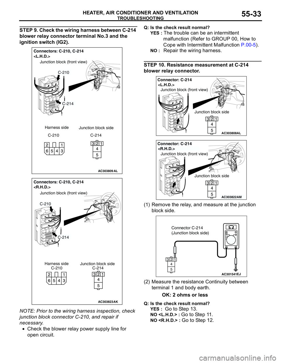
STEP 9. Check the wiring harness between C-214
blower relay connector terminal No.3 and the
ignition switch (IG2).
NOTE: Prior to the wiring harness inspection, check
junction block connector C-210, and repair if
necessary.
•Check the blower relay power supply line for
open circuit.Q: Is the check result normal?
YES :
The trouble can be an intermittent
malfunction (Refer to GROUP 00, How to
Cope with Intermittent Malfunction P.00-5).
NO : Repair the wiring harness.
STEP 10. Resistance measurement at C-214
blower relay connector.
(1) Remove the relay, and measure at the junction
block side.
(2) Measure the resistance Continuity between
terminal 1 and body earth.
OK: 2 ohms or less
Q: Is the check result normal?
YES :
Go to Step 13.
NO
NO
AC303809
Connectors: C-210, C-214
AL
C-214
C-210
Junction block (front view)
C-210 Harness side
Junction block side
C-214
AC303823
Junction block side Junction block (front view)
Connectors: C-210, C-214
C-210C-214 Harness side
C-214
C-210
AK
AC303808
Junction block side Junction block (front view)
Connector: C-214
AL
AC303822
Junction block side Junction block (front view)
Connector: C-214
AM
AC301541EJ
Connector C-214
(Junction block side)
3
4
5
12
Page 518 of 788
TROUBLESHOOTING
HEATER, AIR CONDITIONER AND VENTILATION55-34
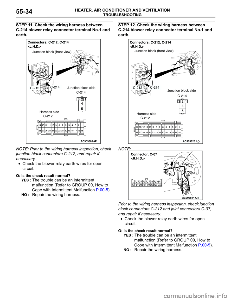
STEP 11. Check the wiring harness between
C-214 blower relay connector terminal No.1 and
earth.
NOTE: Prior to the wiring harness inspection, check
junction block connectors C-212, and repair if
necessary.
•Check the blower relay earth wires for open
circuit.
Q: Is the check result normal?
YES :
The trouble can be an intermittent
malfunction (Refer to GROUP 00, How to
Cope with Intermittent Malfunction P.00-5).
NO : Repair the wiring harness.
STEP 12. Check the wiring harness between
C-214 blower relay connector terminal No.1 and
earth.
NOTE:
Prior to the wiring harness inspection, check junction
block connectors C-212 and joint connectors C-07,
and repair if necessary.
•Check the blower relay earth wires for open
circuit.
Q: Is the check result normal?
YES :
The trouble can be an intermittent
malfunction (Refer to GROUP 00, How to
Cope with Intermittent Malfunction P.00-5).
NO : Repair the wiring harness.
AC303809
Junction block (front view)
Connectors: C-212, C-214
C-212C-214
AP
C-212
Harness side
Junction block side
C-214
AC303823
Connectors: C-212, C-214
AO
Junction block (front view)
C-214C-212Junction block side
C-214
C-212
Harness side
AC303814
Connector: C-07
AR
Page 519 of 788
TROUBLESHOOTING
HEATER, AIR CONDITIONER AND VENTILATION55-35
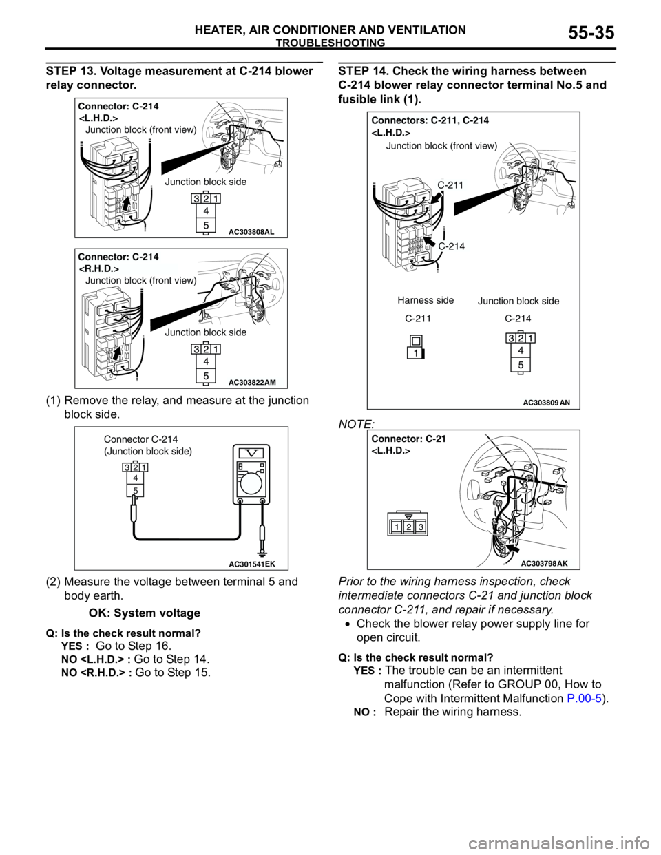
STEP 13. Voltage measurement at C-214 blower
relay connector.
(1) Remove the relay, and measure at the junction
block side.
(2) Measure the voltage between terminal 5 and
body earth.
OK: System voltage
Q: Is the check result normal?
YES :
Go to Step 16.
NO
NO
STEP 14. Check the wiring harness between
C-214 blower relay connector terminal No.5 and
fusible link (1).
NOTE:
Prior to the wiring harness inspection, check
intermediate connectors C-21 and junction block
connector C-211, and repair if necessary.
•Check the blower relay power supply line for
open circuit.
Q: Is the check result normal?
YES :
The trouble can be an intermittent
malfunction (Refer to GROUP 00, How to
Cope with Intermittent Malfunction P.00-5).
NO : Repair the wiring harness.
AC303808
Junction block side Junction block (front view)
Connector: C-214
AL
AC303822
Junction block side Junction block (front view)
Connector: C-214
AM
AC301541EK
Connector C-214
(Junction block side)
3
4
5
12
AC303809
Connectors: C-211, C-214
AN
C-214
C-211
Junction block (front view)
C-211 Harness side
Junction block side
C-214
AC303798
Connector: C-21
AK
Page 520 of 788
TROUBLESHOOTING
HEATER, AIR CONDITIONER AND VENTILATION55-36
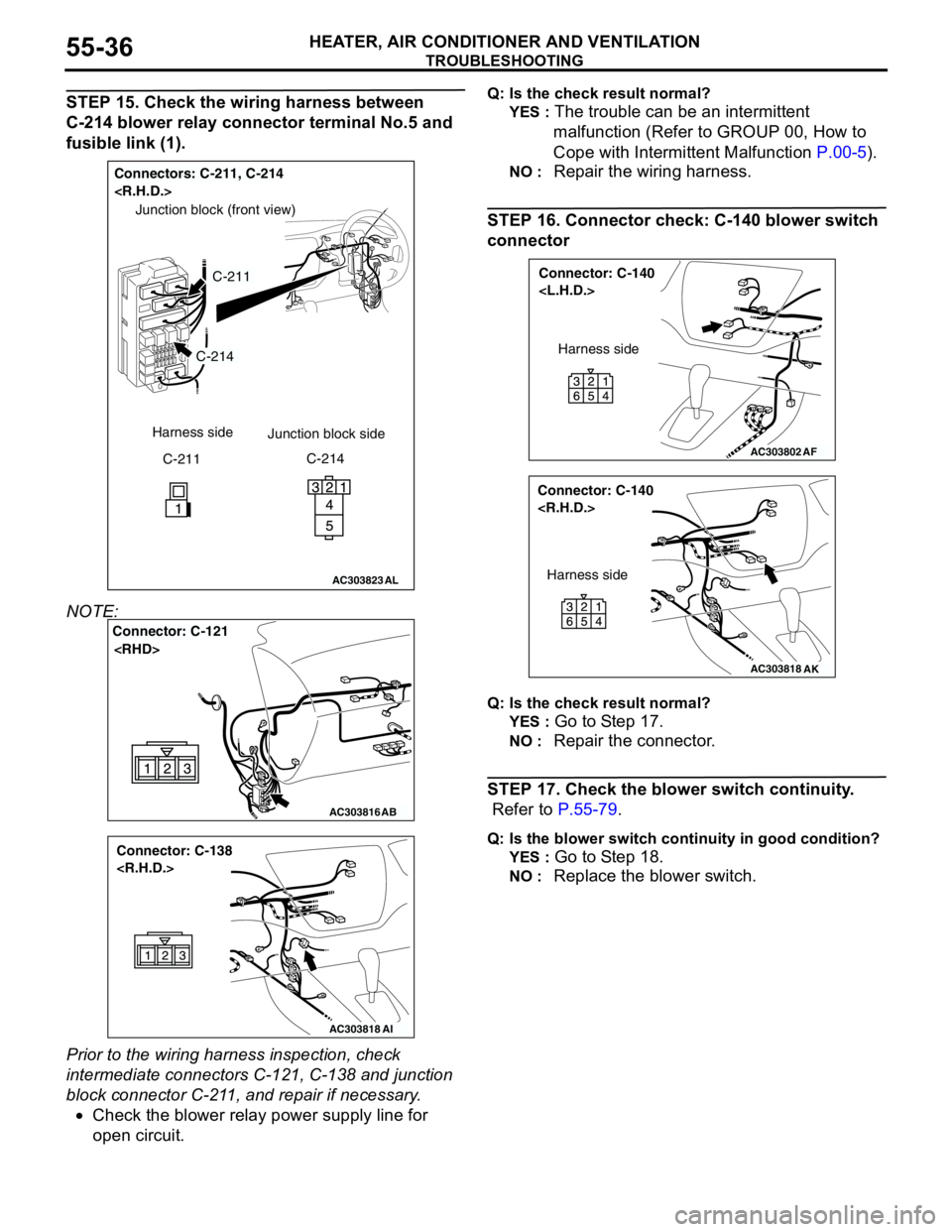
STEP 15. Check the wiring harness between
C-214 blower relay connector terminal No.5 and
fusible link (1).
NOTE:
Prior to the wiring harness inspection, check
intermediate connectors C-121, C-138 and junction
block connector C-211, and repair if necessary.
•Check the blower relay power supply line for
open circuit.Q: Is the check result normal?
YES :
The trouble can be an intermittent
malfunction (Refer to GROUP 00, How to
Cope with Intermittent Malfunction P.00-5).
NO : Repair the wiring harness.
STEP 16. Connector check: C-140 blower switch
connector
Q: Is the check result normal?
YES :
Go to Step 17.
NO : Repair the connector.
STEP 17. Check the blower switch continuity.
Refer to P.55-79.
Q: Is the blower switch continuity in good condition?
YES :
Go to Step 18.
NO : Replace the blower switch.
AC303823
Connectors: C-211, C-214
AL
C-214
C-211
Junction block (front view)
C-211 Harness side
Junction block side
C-214
AC303816
Connector: C-121
AB
AC303818
Connector: C-138
AI
AC303802
Connector: C-140
AF
Harness side
AC303818
Connector: C-140
AK
Harness side