Clutch MITSUBISHI LANCER 2005 User Guide
[x] Cancel search | Manufacturer: MITSUBISHI, Model Year: 2005, Model line: LANCER, Model: MITSUBISHI LANCER 2005Pages: 788, PDF Size: 45.98 MB
Page 496 of 788
TROUBLESHOOTING
HEATER, AIR CONDITIONER AND VENTILATION55-12
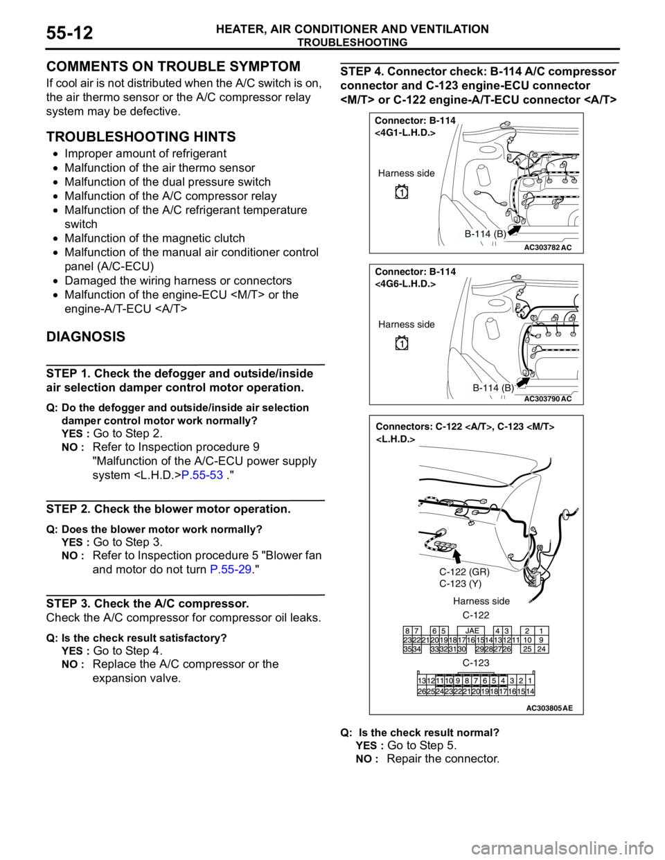
COMMENTS ON TROUBLE SYMPTOM
If cool air is not distributed when the A/C switch is on,
the air thermo sensor or the A/C compressor relay
system may be defective.
TROUBLESHOOTING HINTS
•Improper amount of refrigerant
•Malfunction of the air thermo sensor
•Malfunction of the dual pressure switch
•Malfunction of the A/C compressor relay
•Malfunction of the A/C refrigerant temperature
switch
•Malfunction of the magnetic clutch
•Malfunction of the manual air conditioner control
panel (A/C-ECU)
•Damaged the wiring harness or connectors
•Malfunction of the engine-ECU
engine-A/T-ECU
DIAGNOSIS
STEP 1. Check the defogger and outside/inside
air selection damper control motor operation.
Q: Do the defogger and outside/inside air selection
damper control motor work normally?
YES :
Go to Step 2.
NO : Refer to Inspection procedure 9
"Malfunction of the A/C-ECU power supply
system
STEP 2. Check the blower motor operation.
Q: Does the blower motor work normally?
YES :
Go to Step 3.
NO : Refer to Inspection procedure 5 "Blower fan
and motor do not turn P.55-29."
STEP 3. Check the A/C compressor.
Check the A/C compressor for compressor oil leaks.
Q: Is the check result satisfactory?
YES :
Go to Step 4.
NO : Replace the A/C compressor or the
expansion valve.
STEP 4. Connector check: B-114 A/C compressor
connector and C-123 engine-ECU connector
Q: Is the check result normal?
YES :
Go to Step 5.
NO : Repair the connector.
AC303782
Connector: B-114
<4G1-L.H.D.>
AC
Harness side
B-114 (B)
AC303790
Connector: B-114
<4G6-L.H.D.>
AC
Harness side
B-114 (B)
AC303805
Connectors: C-122 , C-123
C-122 (GR)
C-123 (Y)
C-122 Harness side
C-123
AE
Page 503 of 788
TROUBLESHOOTING
HEATER, AIR CONDITIONER AND VENTILATION55-19
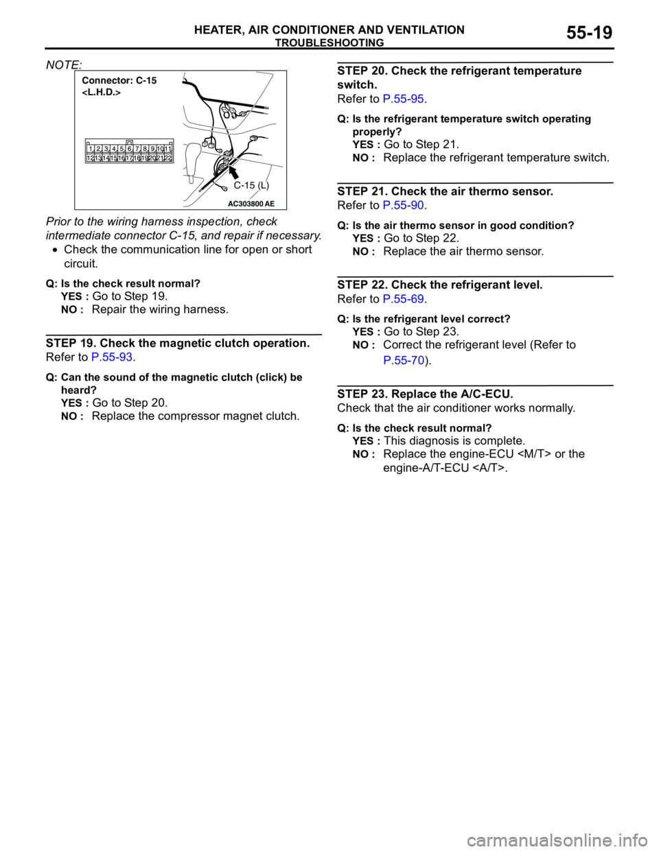
NOTE:
Prior to the wiring harness inspection, check
intermediate connector C-15, and repair if necessary.
•Check the communication line for open or short
circuit.
Q: Is the check result normal?
YES :
Go to Step 19.
NO : Repair the wiring harness.
STEP 19. Check the magnetic clutch operation.
Refer to P.55-93.
Q: Can the sound of the magnetic clutch (click) be
heard?
YES :
Go to Step 20.
NO : Replace the compressor magnet clutch.
STEP 20. Check the refrigerant temperature
switch.
Refer to P.55-95.
Q: Is the refrigerant temperature switch operating
properly?
YES :
Go to Step 21.
NO : Replace the refrigerant temperature switch.
STEP 21. Check the air thermo sensor.
Refer to P.55-90.
Q: Is the air thermo sensor in good condition?
YES :
Go to Step 22.
NO : Replace the air thermo sensor.
STEP 22. Check the refrigerant level.
Refer to P.55-69.
Q: Is the refrigerant level correct?
YES :
Go to Step 23.
NO : Correct the refrigerant level (Refer to
P.55-70).
STEP 23. Replace the A/C-ECU.
Check that the air conditioner works normally.
Q: Is the check result normal?
YES :
This diagnosis is complete.
NO : Replace the engine-ECU
engine-A/T-ECU .
AC303800
Connector: C-15
AE
C-15 (L)
Page 505 of 788
TROUBLESHOOTING
HEATER, AIR CONDITIONER AND VENTILATION55-21
COMMENTS ON TROUBLE SYMPTOM
If cool air is not distributed when the A/C switch is on,
the air thermo sensor or the A/C compressor relay
system may be defective.
TROUBLESHOOTING HINTS
•Improper amount of refrigerant
•Malfunction of the air thermo sensor
•Malfunction of the dual pressure switch
•Malfunction of the A/C compressor relay
•Malfunction of the A/C refrigerant temperature
switch
•Malfunction of the magnetic clutch
•Malfunction of the manual air conditioner control
panel (A/C-ECU)
•Damaged the wiring harness or connectors
•Malfunction of the engine-ECU
engine-A/T-ECU
DIAGNOSIS
STEP 1. Check the defogger and outside/inside
air selection damper control motor operation.
Q: Do the defogger and outside/inside air selection
damper control motor work normally?
YES :
Go to Step 2.
NO : Refer to Inspection procedure 10
"Malfunction of the A/C-ECU power supply
system
STEP 2. Check the blower motor operation.
Q: Does the blower motor work normally?
YES :
Go to Step 3.
NO : Refer to Inspection procedure 5 "Blower fan
and motor do not turn P.55-29."
STEP 3. Check the A/C compressor.
Check the A/C compressor for compressor oil leaks.
Q: Is the check result satisfactory?
YES :
Go to Step 4.
NO : Replace the A/C compressor or the
expansion valve.
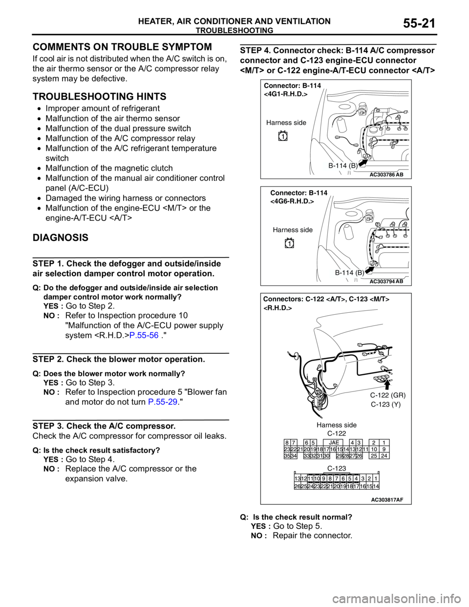
STEP 4. Connector check: B-114 A/C compressor
connector and C-123 engine-ECU connector
Q: Is the check result normal?
YES :
Go to Step 5.
NO : Repair the connector.
AC303786
Connector: B-114
<4G1-R.H.D.>
AB
Harness side
B-114 (B)
AC303794
Connector: B-114
<4G6-R.H.D.>
AB
Harness side
B-114 (B)
AC303817
Connectors: C-122 , C-123
AF
C-122C-122 (GR)
C-123 (Y)
C-123 Harness side
Page 512 of 788
TROUBLESHOOTING
HEATER, AIR CONDITIONER AND VENTILATION55-28
STEP 19. Check the magnetic clutch operation.
Refer to P.55-93.
Q: Can the sound of the magnetic clutch (click) be
heard?
YES :
Go to Step 20.
NO : Replace the compressor magnet clutch.
STEP 20. Check the refrigerant temperature
switch.
Refer to P.55-95.
Q: Is the refrigerant temperature switch operating
properly?
YES :
Go to Step 21.
NO : Replace the refrigerant temperature switch.
STEP 21. Check the air thermo sensor.
Refer to P.55-90.
Q: Is the air thermo sensor in good condition?
YES :
Go to Step 22.
NO : Replace the air thermo sensor.
STEP 22. Check the refrigerant level.
Refer to P.55-69.
Q: Is the refrigerant level correct?
YES :
Go to Step 23.
NO : Correct the refrigerant level (Refer to
On-vehicle Service P.55-70).
STEP 23. Replace the A/C-ECU.
Check that the air conditioner works normally.
Q: Is the check result normal?
YES :
This diagnosis is complete.
NO : Replace the engine-ECU
engine-A/T-ECU .
Page 543 of 788
TROUBLESHOOTING
HEATER, AIR CONDITIONER AND VENTILATION55-59
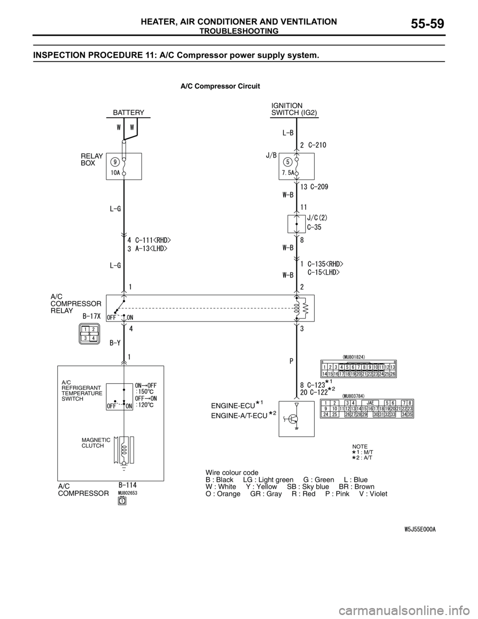
INSPECTION PROCEDURE 11: A/C Compressor power supply system.
A/C
COMPRESSOR
RELAY
A/C
COMPRESSOR
A/C
REFRIGERANT
TEMPERATURE
SWITCH
MAGNETIC
CLUTCH
IGNITION
SWITCH (IG2)
ENGINE-ECU BATTERY
RELAY
BOX
ENGINE-A/T-ECU
Wire colour code
B : Black LG : Light green G : Green L : Blue
W : White Y : Yellow SB : Sky blue BR : Brown
O : Orange GR : Gray R : Red P : Pink V : Violet
: M/T
: A/TNOTE
A/C Compressor Circuit
Page 553 of 788
ON-VEHICLE SERVICE
HEATER, AIR CONDITIONER AND VENTILATION55-69
ON-VEHICLE SERVICE
SIGHT GLASS REFRIGERANT LEVEL
TEST
M1552008400378
1. Start the engine.
2. Operate the air-conditioner, and then set the
temperature to maximum cooling.
3. Hold the engine speed at 1500 r/min.
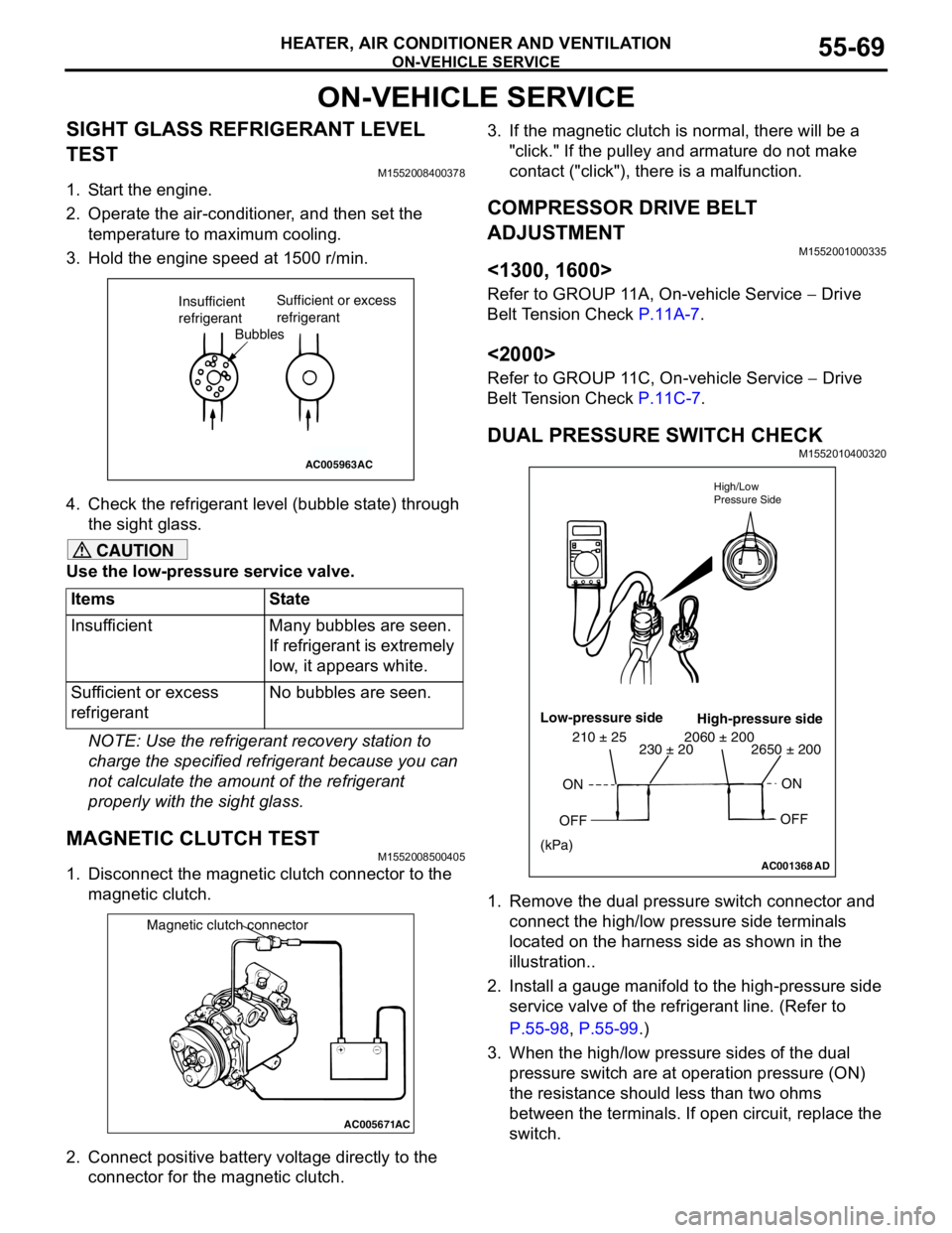
4. Check the refrigerant level (bubble state) through
the sight glass.
CAUTION
Use the low-pressure service valve.
NOTE: Use the refrigerant recovery station to
charge the specified refrigerant because you can
not calculate the amount of the refrigerant
properly with the sight glass.
MAGNETIC CLUTCH TESTM1552008500405
1. Disconnect the magnetic clutch connector to the
magnetic clutch.
2. Connect positive battery voltage directly to the
connector for the magnetic clutch.3. If the magnetic clutch is normal, there will be a
"click." If the pulley and armature do not make
contact ("click"), there is a malfunction.
COMPRESSOR DRIVE BELT
ADJUSTMENT
M1552001000335
<1300, 1600>
Refer to GROUP 11A, On-vehicle Service − Drive
Belt Tension Check P.11A-7.
<2000>
Refer to GROUP 11C, On-vehicle Service − Drive
Belt Tension Check P.11C-7.
DUAL PRESSURE SWITCH CHECKM1552010400320
1. Remove the dual pressure switch connector and
connect the high/low pressure side terminals
located on the harness side as shown in the
illustration..
2. Install a gauge manifold to the high-pressure side
service valve of the refrigerant line. (Refer to
P.55-98, P.55-99.)
3. When the high/low pressure sides of the dual
pressure switch are at operation pressure (ON)
the resistance should less than two ohms
between the terminals. If open circuit, replace the
switch. Items State
Insufficient Many bubbles are seen.
If refrigerant is extremely
low, it appears white.
Sufficient or excess
refrigerantNo bubbles are seen.
AC005963
Bubbles Insufficient
refrigerantSufficient or excess
refrigerant
AC
AC005671
Magnetic clutch connector
AC
AC001368AD High/Low
Pressure Side
Low-pressure side
High-pressure side
ON
OFFON
OFF
2650 ± 200 2060 ± 200230 ± 20 210 ± 25
(kPa)
Page 557 of 788
ON-VEHICLE SERVICE
HEATER, AIR CONDITIONER AND VENTILATION55-73
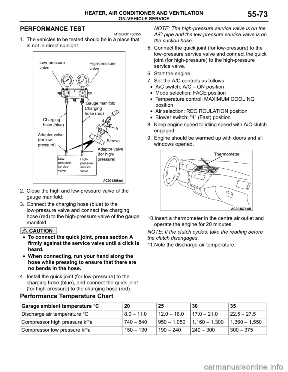
PERFORMANCE TEST M1552001400355
1. The vehicles to be tested should be in a place that
is not in direct sunlight.
2. Close the high and low-pressure valve of the
gauge manifold.
3. Connect the charging hose (blue) to the
low-pressure valve and connect the charging
hose (red) to the high-pressure valve of the gauge
manifold.
CAUTION
•To connect the quick joint, press section A
firmly against the service valve until a click is
heard.
•When connecting, run your hand along the
hose while pressing to ensure that there are
no bends in the hose.
4. Install the quick joint (for low-pressure) to the
charging hose (blue), and connect the quick joint
(for high-pressure) to the charging hose (red).NOTE: The high-pressure service valve is on the
A/C pipe and the low-pressure service valve is on
the suction hose.
5. Connect the quick joint (for low-pressure) to the
low-pressure service valve and connect the quick
joint (for high-pressure) to the high-pressure
service valve.
6. Start the engine.
7. Set the A/C controls as follows:
•A/C switch: A/C − ON position
•Mode selection: FACE position
•Temperature control: MAXIMUM COOLING
position
•Air selection: RECIRCULATION position
•Blower switch: "4" (Fast) position
8. Keep engine speed to idling speed with A/C clutch
engaged.
9. Engine should be warmed up with doors and all
windows opened.
10.Insert a thermometer in the centre air outlet and
operate the engine for 20 minutes.
NOTE: If the clutch cycles, take the reading before
the clutch disengages.
11.Note the discharge air temperature.
Performance Temperature Chart
AC001388
Low-pressure
valveHigh-pressure
valve
Gauge manifold
Charging
hose (red)
A
Sleeve Charging
hose (blue)
Adaptor valve
(for low-
pressure)
Low-
pressure
service
valveHigh-
pressure
service
valve
AB
Adaptor valve
(for high-
pressure)
AC304576
Thermometer
AB
Garage ambient temperature °C20 25 30 35
Discharge air temperature °C8.0 − 11.0 12.0 − 16.0 17.0 − 21.0 22.5 − 27.5
Compressor high pressure kPa 740 − 840 950 − 1,050 1,160 − 1,300 1,360 − 1,550
Compressor low pressure kPa 150 − 190 190 − 240 240 − 300 300 − 375
Page 558 of 788
ON-VEHICLE SERVICE
HEATER, AIR CONDITIONER AND VENTILATION55-74
REFRIGERANT LEAK REPAIR
PROCEDURE
M1552001500277
LOST CHARGE
If the system has lost all charge due to a leak:
1. Evacuate the system (Refer to P.55-72).
2. Charge the system with approximately 480 − 520
g of refrigerant.
3. Check for leaks.
4. Discharge the system.
5. Repair leaks.
CAUTION
Replacement filter-drier units must be sealed
while in storage. The drier used in these units will
saturate water quickly upon exposure to the
atmosphere. When installing a drier, have all
tools and supplies ready for quick assembly to
avoid keeping the system open any longer than
necessary.
6. Replace receiver drier.
7. Evacuate and charge system.
LOW CHARGE
If the system has not lost all of its refrigerant charge;
locate and repair all leaks. If it is necessary to
increase the system pressure to find the leak
(because of an especially low charge) add
refrigerant. If it is possible to repair the leak without
discharging the refrigerant system, use the
procedure for correcting low refrigerant level.
HANDLING TUBING AND FITTINGS
Kinks in the refrigerant tubing or sharp bends in the
refrigerant hose lines will greatly reduce the capacity
of the entire system. High pressures are produced in
the system when it is operating. Extreme care must
be exercised to make sure that all connections are
pressure tight. Dirt and moisture can enter the
system when it is opened for repair or replacement of
lines or components. The following precautions must
be observed. The system must be completely
discharged before opening any fitting of connection
in the refrigeration system. Open fittings with caution
even after the system has been discharged. If any
pressure is noticed as a fitting is loosened, allow
trapped pressure to bleed off very slowly.
Never attempt to rebend formed lines to fit. Use the
correct line for the installation you are servicing. A
good rule for the flexible hose lines is keep the radius
of all bends at least 10 times the diameter of the
hose.Sharper bends will reduce the flow of refrigerant. The
flexible hose lines should be routed so that they are
at least 80 mm from the exhaust manifold. It is good
practice to inspect all flexible hose lines at least once
a year to make sure they are in good condition and
properly routed.
On standard plumbing fittings with O-rings, these
O-rings are not reusable.
COMPRESSOR NOISE CHECKM1552008700272
You must first know the conditions when the noise
occurs. These conditions are: weather, vehicle
speed, in gear or neutral, engine temperature or any
other special conditions.
Noises that develop during A/C operation can often
be misleading. For example: what sounds like a
failed front bearing or connecting rod, may be
caused by loose bolts, nuts, mounting brackets, or a
loose clutch assembly. Verify accessory drive belt
tension (power steering or alternator).
Improper accessory drive belt tension can cause a
misleading noise when the compressor is engaged
and little or no noise when the compressor is
disengaged.
Drive belts are speed-sensitive. That is, at different
engine speeds, and depending upon belt tension,
belts can develop unusual noises that are often
mistaken for mechanical problems within the
compressor.
ADJUSTMENT
1. Select a quiet area for testing. Duplicate
conditions as much as possible. Switch the
compressor on and off several times to clearly
identify compressor noise. To duplicate high
ambient conditions (high head pressure), restrict
air flow through the condenser. Install a manifold
gauge set to make sure discharge pressure
doesn't exceed 2,070 kPa.
2. Tighten all compressor mounting bolts, clutch
mounting bolt, and compressor drive belt. Check
to assure clutch coil is tight (no rotation or
wobble).
3. Check refrigerant hoses for rubbing or
interference that can cause unusual noises.
4. Check refrigerant charge (Refer to P.55-69).
5. Recheck compressor noise as in Step 1.
6. If noise still exists, loosen compressor mounting
bolts and retighten. Repeat Step 1.
7. If noise continues, replace compressor and repeat
Step 1.
Page 577 of 788

COMPRESSOR ASSEMBLY AND TENSION PULLEY
HEATER, AIR CONDITIONER AND VENTILATION55-93
INSTALLATION SERVICE POINT
>>A<< A/C COMPRESSOR
INSTALLATION
If a new compressor is installed, first adjust the
amount of oil according to the procedures described
below, and then install the compressor.
1. Measure the amount (X mL) of oil within the
removed compressor.
2. Drain (from the new compressor) the amount of
oil calculated according to the following formula,
and then install the new compressor.
New compressor oil amount = 140mL <1300,
1600>, 120 mL <2000>
140 mL−X mL = Y mL <1300, 1600>
120 mL−X mL = Y mL <2000>
NOTE: Y mL indicates the amount of oil in the
refrigerant line, the condenser, the evaporator, etc.
NOTE: When replacing the following parts at the
same times as the compressor, subtract the rated oil
amount of the each part from Y mL and discharge
from the new compressor.
Quantity:
•Evaporator: 60 mL
•Condenser: 15 mL
•Suction hose: 10 mL
•Receiver: 10 mL
INSPECTIONM1552014300949
COMPRESSOR MAGNETIC CLUTCH
OPERATION CHECK
Connect the compressor connector terminal to the
battery positive (+) terminal and earth the battery’s
negative (−) terminal to the compressor unit. At that
time, the magnetic clutch should make a definite
operating sound.
AC005671
Magnetic clutch connector
AC
Page 578 of 788
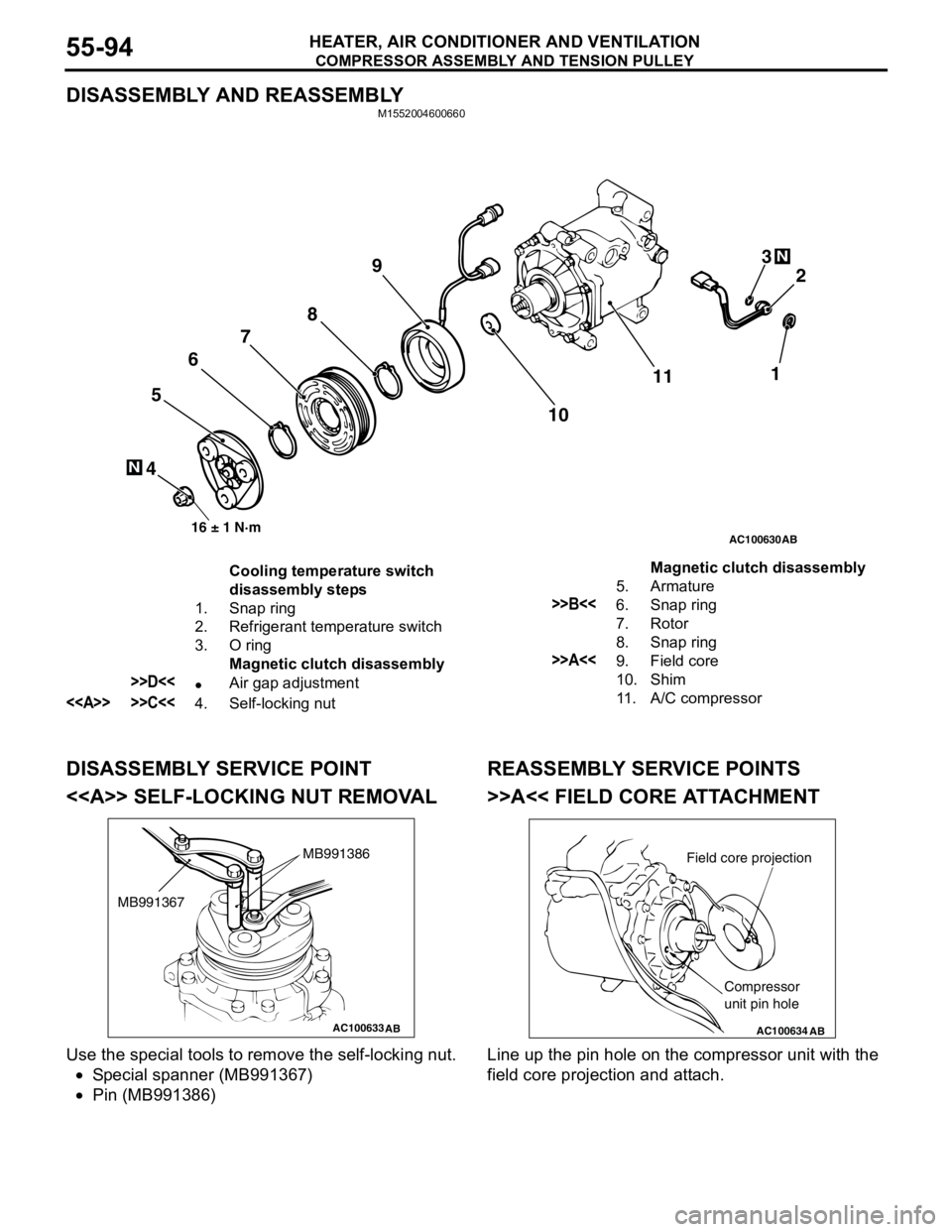
COMPRESSOR ASSEMBLY AND TENSION PULLEY
HEATER, AIR CONDITIONER AND VENTILATION55-94
DISASSEMBLY AND REASSEMBLYM1552004600660
DISASSEMBLY SERVICE POINT
<> SELF-LOCKING NUT REMOVAL
Use the special tools to remove the self-locking nut.
•Special spanner (MB991367)
•Pin (MB991386)
REASSEMBLY SERVICE POINTS
>>A<< FIELD CORE ATTACHMENT
Line up the pin hole on the compressor unit with the
field core projection and attach.
AC100630
N
N
16 ± 1 N·m
10
46789
512
AB
3
11
Cooling temperature switch
disassembly steps
1. Snap ring
2. Refrigerant temperature switch
3. O ring
Magnetic clutch disassembly
>>D<<•Air gap adjustment
<> >>C<<4. Self-locking nut5. Armature
>>B<<6. Snap ring
7. Rotor
8. Snap ring
>>A<<9. Field core
10. Shim
11. A/C compressorMagnetic clutch disassembly
AC100633AB
MB991386
MB991367
AC100634AB
Field core projection
Compressor
unit pin hole