Rake MITSUBISHI LANCER 2005 User Guide
[x] Cancel search | Manufacturer: MITSUBISHI, Model Year: 2005, Model line: LANCER, Model: MITSUBISHI LANCER 2005Pages: 788, PDF Size: 45.98 MB
Page 160 of 788
ON-VEHICLE SERVICE
REAR AXLE27-4
ON-VEHICLE SERVICE
WHEEL BEARING AXIAL PLAY CHECKM1271000900452
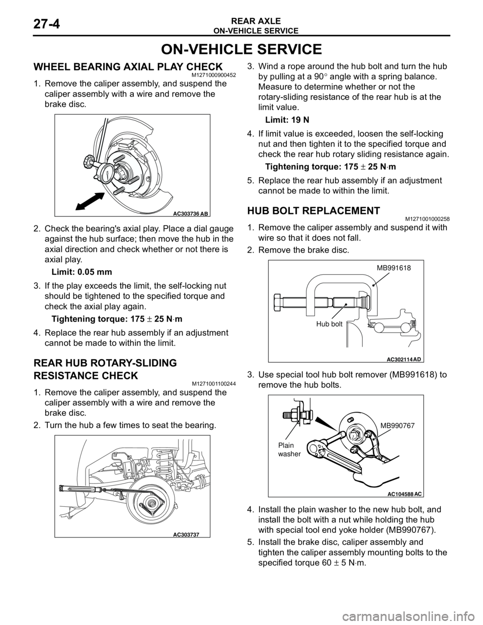
1. Remove the caliper assembly, and suspend the
caliper assembly with a wire and remove the
brake disc.
2. Check the bearing's axial play. Place a dial gauge
against the hub surface; then move the hub in the
axial direction and check whether or not there is
axial play.
Limit: 0.05 mm
3. If the play exceeds the limit, the self-locking nut
should be tightened to the specified torque and
check the axial play again.
Tightening torque: 175 ± 25 N⋅m
4. Replace the rear hub assembly if an adjustment
cannot be made to within the limit.
REAR HUB ROTARY-SLIDING
RESISTANCE CHECK
M1271001100244
1. Remove the caliper assembly, and suspend the
caliper assembly with a wire and remove the
brake disc.
2. Turn the hub a few times to seat the bearing.3. Wind a rope around the hub bolt and turn the hub
by pulling at a 90° angle with a spring balance.
Measure to determine whether or not the
rotary-sliding resistance of the rear hub is at the
limit value.
Limit: 19 N
4. If limit value is exceeded, loosen the self-locking
nut and then tighten it to the specified torque and
check the rear hub rotary sliding resistance again.
Tightening torque: 175 ± 25 N⋅m
5. Replace the rear hub assembly if an adjustment
cannot be made to within the limit.
HUB BOLT REPLACEMENTM1271001000258
1. Remove the caliper assembly and suspend it with
wire so that it does not fall.
2. Remove the brake disc.
3. Use special tool hub bolt remover (MB991618) to
remove the hub bolts.
4. Install the plain washer to the new hub bolt, and
install the bolt with a nut while holding the hub
with special tool end yoke holder (MB990767).
5. Install the brake disc, caliper assembly and
tighten the caliper assembly mounting bolts to the
specified torque 60 ± 5 N⋅m.
AC303736AB
AC303737
AC302114
MB991618
AD
Hub bolt
AC104588
MB990767
Plain
washer
AC
Page 161 of 788
REAR AXLE HUB ASSEMBLY
REAR AXLE27-5
REAR AXLE HUB ASSEMBLY
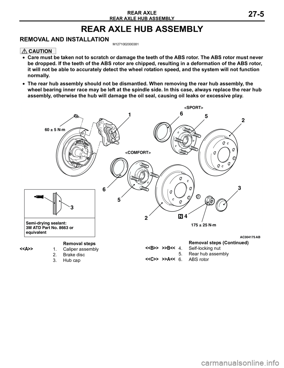
REMOVAL AND INSTALLATIONM1271002000381
CAUTION
•Care must be taken not to scratch or damage the teeth of the ABS rotor. The ABS rotor must never
be dropped. If the teeth of the ABS rotor are chipped, resulting in a deformation of the ABS rotor,
it will not be able to accurately detect the wheel rotation speed, and the system will not function
normally.
•The rear hub assembly should not be dismantled. When removing the rear hub assembly, the
wheel bearing inner race may be left at the spindle side. In this case, always replace the rear hub
assembly, otherwise the hub will damage the oil seal, causing oil leaks or excessive play.
AC304175
Semi-drying sealant:
3M ATD Part No. 8663 or
equivalent
2
3
5 6
4
N
175 ± 25 N·m
3
AB
1
60 ± 5 N·m
2
56
Removal steps
<>1. Caliper assembly
2. Brake disc
3. Hub cap<> >>B<<4. Self-locking nut
5. Rear hub assembly
<
Page 189 of 788
STRUT ASSEMBLY
FRONT SUSPENSION33-7
STRUT ASSEMBLY
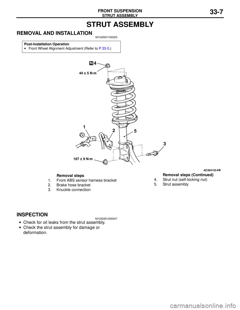
REMOVAL AND INSTALLATIONM1332001100325
INSPECTIONM1332001200247
•Check for oil leaks from the strut assembly.
•Check the strut assembly for damage or
deformation.
Post-installation Operation
•Front Wheel Alignment Adjustment (Refer to P.33-5.)
AC304153
44 ± 5 N·m
1
2
3 4
N
AB
167 ± 9 N·m
5
Removal steps
1. Front ABS sensor harness bracket
2. Brake hose bracket
3. Knuckle connection4. Strut nut (self-locking nut)
5. Strut assemblyRemoval steps (Continued)
Page 212 of 788

TRAILING ARM ASSEMBLY
REAR SUSPENSION34-12
TRAILING ARM ASSEMBLY
REMOVAL AND INSTALLATIONM1341002200594
CAUTION
*: Indicates parts which should be temporarily tightened, and then fully tightened with the vehicle on
the earth in the unladen condition.
Pre-removal Operation
•Brake Fluid Draining
•Rear Hub Assembly Removal (Refer to GROUP 27, Rear
Axle Hub Assembly P.27-5).Post-installation Operation
•Rear Hub Assembly Installation (Refer to GROUP 27,
Rear Axle Hub Assembly P.27-5).
•Brake Fluid Supplying and Bleeding (Refer to GROUP
35A, On-vehicle Service − Bleeding P.35A-6).
•Rear Wheel Alignment Check and Adjustment (Refer to
P.34-5).
•Parking Brake Lever Stroke Adjustment (Refer to GROUP
36, On-vehicle Service − Parking Brake Lever Stroke
Check and Adjustment P.36-3).
AC101449
AC301223
AC304155AB
90 ± 10 N·m*
120 ± 10 N·m*
95 ± 15 N·m*63 ± 7 N·m
6 78
1 1011
23
4
120 ± 10 N·m*
15 ± 2 N·m
N
9
5
Removal steps
<>•Lifting point
1. Rear ABS Sensor (Refer to
GROUP 35B, ABS Sensor
P.35B-71).
2. Parking brake cable
3. Brake hose and trailing arm
connection
4. Rear parking brake assembly>>A<<5. Lower arm assembly and stabilizer
link connection
6. Lower arm assembly and shock
absorber connection
7. Control link and trailing arm
connection
8. Upper arm assembly and trailing
arm connection Removal steps (Continued)
Page 223 of 788

35-1
GROUP 35
SERVICE BRAKES
CONTENTS
BASIC BRAKE SYSTEM . . . . . . . . . . . . . . . . . . . . . . . . . . . . . .35A
ANTI-SKID BRAKING SYSTEM (ABS) . . . . . . . . . . . . . . . . . . .35B
Page 225 of 788

36-1
GROUP 36
PARKING BRAKES
CONTENTS
GENERAL INFORMATION . . . . . . . .36-2
SERVICE SPECIFICATIONS . . . . . . .36-2
LUBRICANTS . . . . . . . . . . . . . . . . . .36-3
ON-VEHICLE SERVICE . . . . . . . . . . .36-3
PARKING BRAKE LEVER STROKE
CHECK AND ADJUSTMENT . . . . . . . . . . . 36-3
LINING RUNNING-IN . . . . . . . . . . . . . . . . . 36-3
PARKING BRAKE SWITCH CHECK . . . . . 36-4
PARKING BRAKE LEVER . . . . . . . . .36-5
REMOVAL AND INSTALLATION . . . . . . . . 36-5
PARKING BRAKE CABLE . . . . . . . . .36-6
REMOVAL AND INSTALLATION . . . . . . . . 36-6
PARKING BRAKE LINING AND
DRUM . . . . . . . . . . . . . . . . . . . . . . . . .36-7
REMOVAL AND INSTALLATION . . . . . . . . 36-7
INSPECTION . . . . . . . . . . . . . . . . . . . . . . . . 36-9
Page 226 of 788
GENERAL INFORMATION
PARKING BRAKES36-2
GENERAL INFORMATION
M1361000100496
The parking brake is of a mechanical rear-wheel
acting type, and its operation utilises a parking brake
lever.
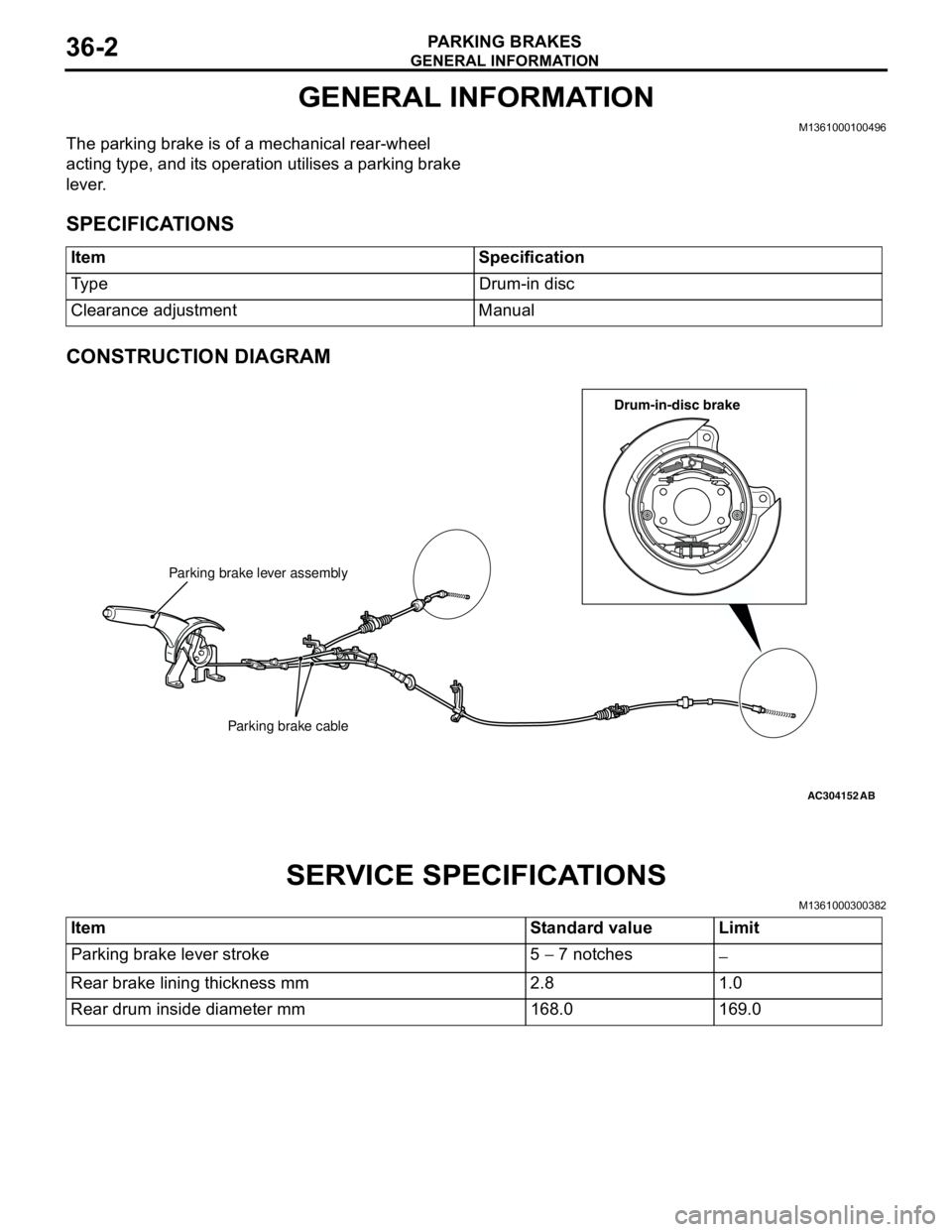
SPECIFICATIONS
CONSTRUCTION DIAGRAM
SERVICE SPECIFICATIONS
M1361000300382
Item Specification
Type Drum-in disc
Clearance adjustment Manual
AC211553
AC104333
AC304152
Parking brake lever assembly
Parking brake cable
AB
Drum-in-disc brake
Item Standard value Limit
Parking brake lever stroke 5 − 7 notches
−
Rear brake lining thickness mm 2.8 1.0
Rear drum inside diameter mm 168.0 169.0
Page 227 of 788
LUBRICANTS
PARKING BRAKES36-3
LUBRICANTS
M1361000400293
ON-VEHICLE SERVICE
PARKING BRAKE LEVER STROKE
CHECK AND ADJUSTMENT
M1361000900339
1. Pull the parking brake lever with a force of
approximately 200 N and count the number of
notches.
Standard value: 5 − 7 notches
2. If the parking brake lever stroke is not the
standard value, adjust as described below.
(1) Remove the rear console assembly (Refer to
GROUP 52A, Rear Floor Console P.52A-8).
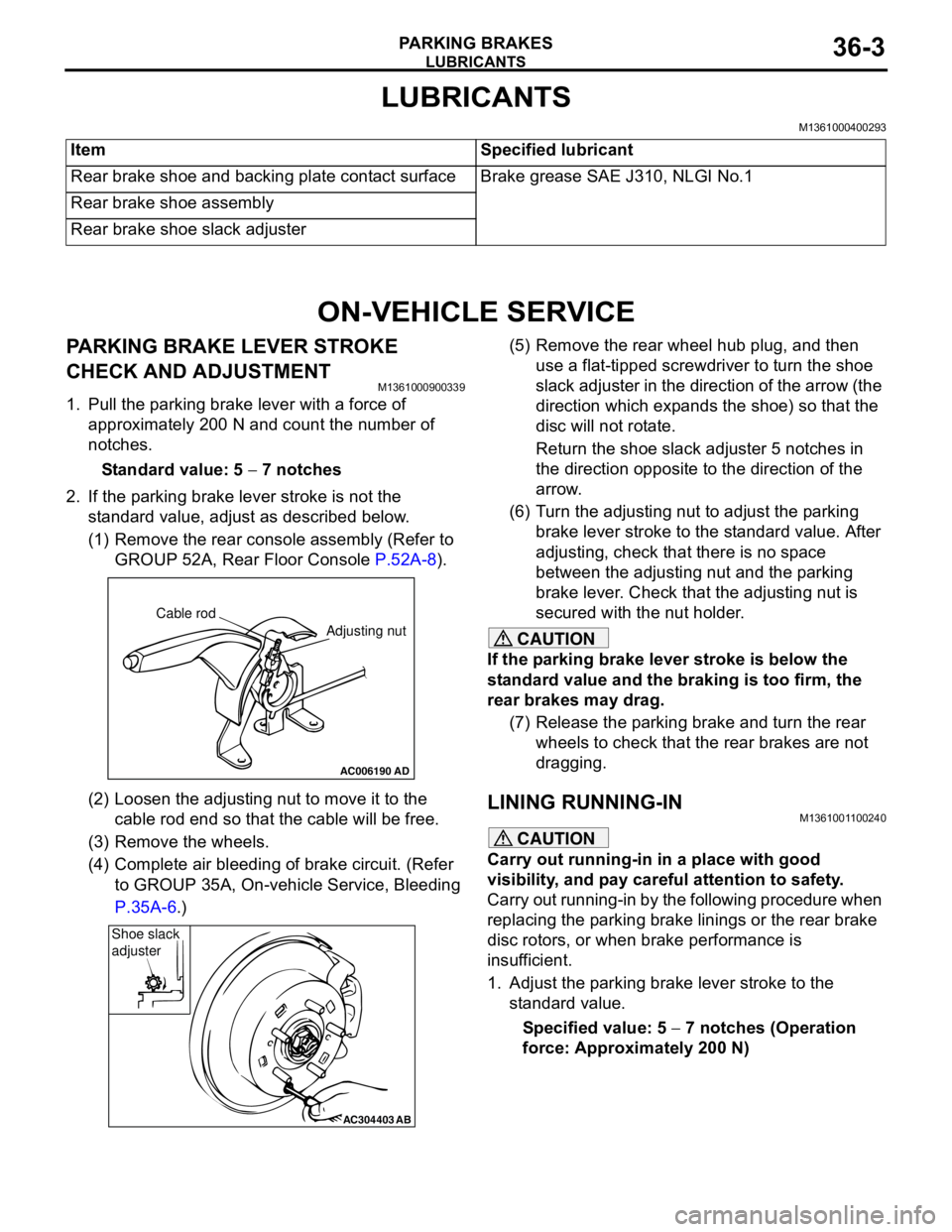
(2) Loosen the adjusting nut to move it to the
cable rod end so that the cable will be free.
(3) Remove the wheels.
(4) Complete air bleeding of brake circuit. (Refer
to GROUP 35A, On-vehicle Service, Bleeding
P.35A-6.)(5) Remove the rear wheel hub plug, and then
use a flat-tipped screwdriver to turn the shoe
slack adjuster in the direction of the arrow (the
direction which expands the shoe) so that the
disc will not rotate.
Return the shoe slack adjuster 5 notches in
the direction opposite to the direction of the
arrow.
(6) Turn the adjusting nut to adjust the parking
brake lever stroke to the standard value. After
adjusting, check that there is no space
between the adjusting nut and the parking
brake lever. Check that the adjusting nut is
secured with the nut holder.
CAUTION
If the parking brake lever stroke is below the
standard value and the braking is too firm, the
rear brakes may drag.
(7) Release the parking brake and turn the rear
wheels to check that the rear brakes are not
dragging.
LINING RUNNING-INM1361001100240
CAUTION
Carry out running-in in a place with good
visibility, and pay careful attention to safety.
Carry out running-in by the following procedure when
replacing the parking brake linings or the rear brake
disc rotors, or when brake performance is
insufficient.
1. Adjust the parking brake lever stroke to the
standard value.
Specified value: 5 − 7 notches (Operation
force: Approximately 200 N) Item Specified lubricant
Rear brake shoe and backing plate contact surface Brake grease SAE J310, NLGI No.1
Rear brake shoe assembly
Rear brake shoe slack adjuster
AC006190
Cable rod
Adjusting nut
AD
AC304403AB
Shoe slack
adjuster
Page 228 of 788
ON-VEHICLE SERVICE
PARKING BRAKES36-4
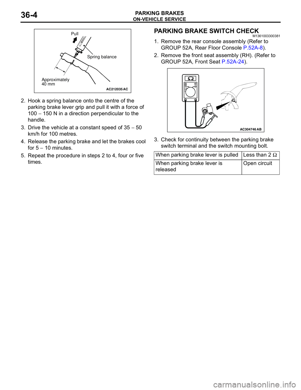
2. Hook a spring balance onto the centre of the
parking brake lever grip and pull it with a force of
100 − 150 N in a direction perpendicular to the
handle.
3. Drive the vehicle at a constant speed of 35 − 50
km/h for 100 metres.
4. Release the parking brake and let the brakes cool
for 5 − 10 minutes.
5. Repeat the procedure in steps 2 to 4, four or five
times.
PARKING BRAKE SWITCH CHECKM1361003300381
1. Remove the rear console assembly (Refer to
GROUP 52A, Rear Floor Console P.52A-8).
2. Remove the front seat assembly (RH). (Refer to
GROUP 52A, Front Seat P.52A-24).
3. Check for continuity between the parking brake
switch terminal and the switch mounting bolt.
AC212035AC
Spring balance
Approximately
40 mmPull
When parking brake lever is pulled Less than 2 Ω
When parking brake lever is
releasedOpen circuit
AC304746AB
Page 229 of 788
PARKING BRAKE LEVER
PARKING BRAKES36-5
PARKING BRAKE LEVER
REMOVAL AND INSTALLATIONM1361001300330
Pre-removal Operation
Rear Console Assembly and Rear Console Bracket Removal
(Refer to GROUP 52A, Rear Floor Console P.52A-8.)Post-installation Operation
•Parking Brake Lever Stroke Adjustment (Refer to P.36-3.)
•Rear Console Bracket and Rear Console Assembly
Installation (Refer to GROUP 52A, Rear Floor Console
P.52A-8.)
AC006199AB
4
5
21
3
A
AB
B
Ratchet pawlSection A - A
Section B - B
Ratchet pawl
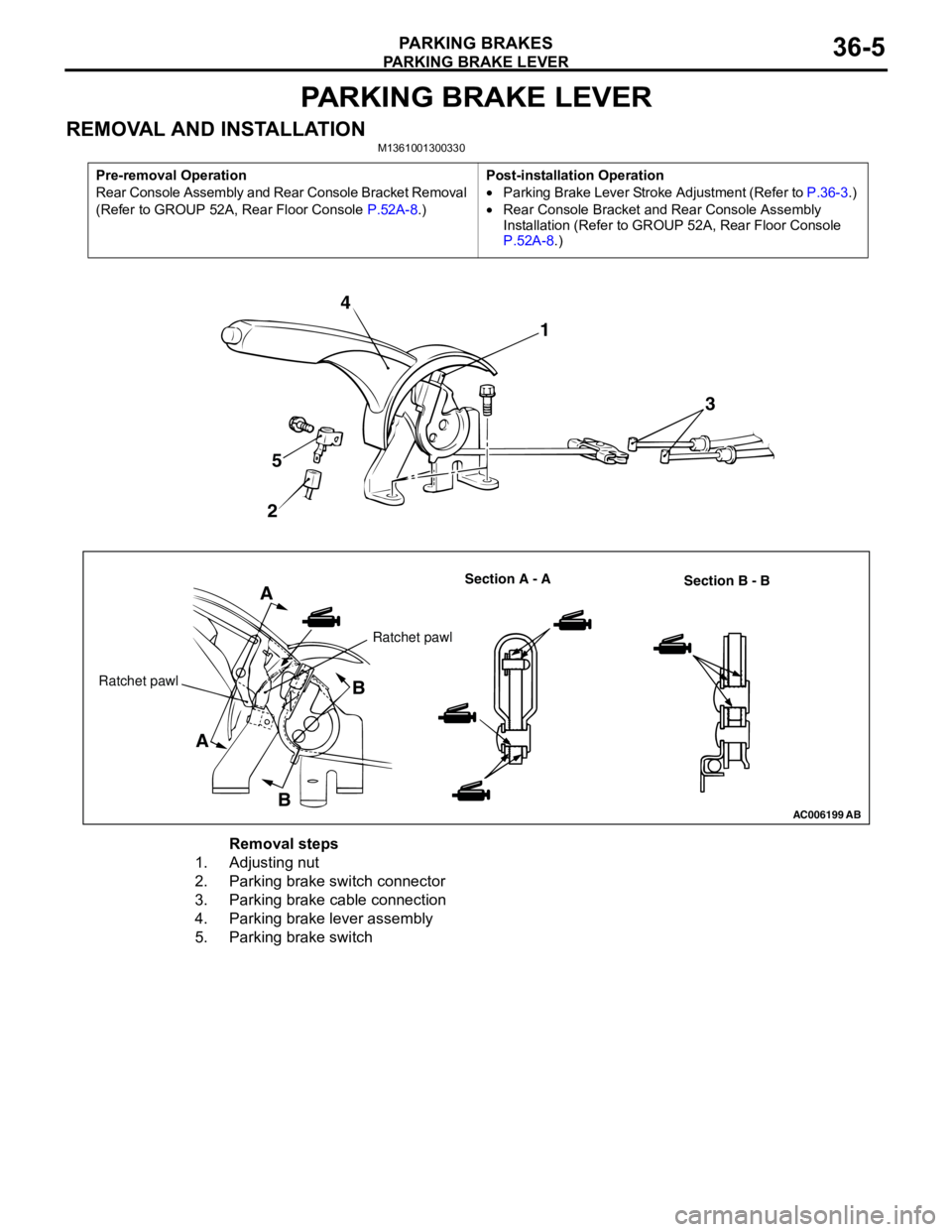
Removal steps
1. Adjusting nut
2. Parking brake switch connector
3. Parking brake cable connection
4. Parking brake lever assembly
5. Parking brake switch