Rake MITSUBISHI LANCER 2005 Workshop Manual
[x] Cancel search | Manufacturer: MITSUBISHI, Model Year: 2005, Model line: LANCER, Model: MITSUBISHI LANCER 2005Pages: 788, PDF Size: 45.98 MB
Page 1 of 788
GROUP INDEX
00General . . . . . . . . . . . . . . . . . . . . . . . .
11Engine. . . . . . . . . . . . . . . . . . . . . . . . .
12Engine Lubrication . . . . . . . . . . . . . .
13Fuel . . . . . . . . . . . . . . . . . . . . . . . . . . .
14Engine Cooling . . . . . . . . . . . . . . . . .
15Intake and Exhaust . . . . . . . . . . . . . .
16Engine Electrical . . . . . . . . . . . . . . . .
17Engine and Emission Control . . . . .
21Clutch . . . . . . . . . . . . . . . . . . . . . . . . .
22Manual Transmission . . . . . . . . . . . .
23Automatic Transmission. . . . . . . . . .
26Front Axle . . . . . . . . . . . . . . . . . . . . . .
27Rear Axle . . . . . . . . . . . . . . . . . . . . . .
31Wheel and Tyre . . . . . . . . . . . . . . . . .
32Power Plant Mount . . . . . . . . . . . . . .
33Front Suspension . . . . . . . . . . . . . . .
34Rear Suspension . . . . . . . . . . . . . . . .
35Service Brakes . . . . . . . . . . . . . . . . . .
36Parking Brakes . . . . . . . . . . . . . . . . .
37Power Steering . . . . . . . . . . . . . . . . .
42Body . . . . . . . . . . . . . . . . . . . . . . . . . .
51Exterior . . . . . . . . . . . . . . . . . . . . . . . .
52 . . . . . . . . . .
54Chassis Electrical . . . . . . . . . . . . . . .
55 . . . . . . .
70Component Locations. . . . . . . . . . . .
80Configration Diagrams . . . . . . . . . . .
90Circuit Diagrams . . . . . . . . . . . . . . . .
LANCER /
LANCER WAGON
WORKSHOP MANUAL
FOREWORD
This Workshop manual contains procedures for
service mechanics, including removal, disassembly,
inspection, adjustment, reassembly and installation.
Use the following manuals in combination with this
manual as required.
TECHNICAL INFORMATION MANUAL
PYME0302
PYME0302-A
WORKSHOP MANUAL
CHASSIS GROUP PWME0302
BODY REPAIR MANUAL
PBME0302
PBME0302-A
PARTS CATALOGUE
B606K005A_
All information, illustrations and product descriptions
contained in this manual are current as at the time of
publication. We, however, reserve the right to make
changes at any time without prior notice or obligation.
Mitsubishi Motors Corporation May 2004
Heater, Air Conditioner and
Ventilation Interior and Supplemental
Restraint System (SRS)
Page 57 of 788
INLET MANIFOLD
INTAKE AND EXHAUST15-5
INLET MANIFOLD
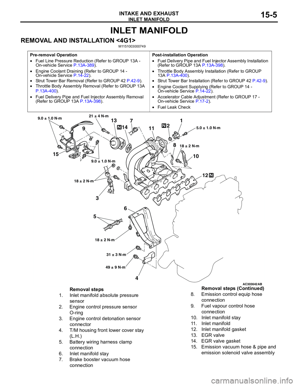
REMOVAL AND INSTALLATION <4G1>M1151003000749
Pre-removal Operation
•Fuel Line Pressure Reduction (Refer to GROUP 13A -
On-vehicle Service P.13A-389).
•Engine Coolant Draining (Refer to GROUP 14 -
On-vehicle Service P.14-22).
•Strut Tower Bar Removal (Refer to GROUP 42 P.42-9).
•Throttle Body Assembly Removal (Refer to GROUP 13A
P.13A-400).
•Fuel Delivery Pipe and Fuel Injector Assembly Removal
(Refer to GROUP 13A P.13A-398).Post-installation Operation
•Fuel Delivery Pipe and Fuel Injector Assembly Installation
(Refer to GROUP 13A P.13A-398).
•Throttle Body Assembly Installation (Refer to GROUP
13A P.13A-400).
•Strut Tower Bar Installation (Refer to GROUP 42 P.42-9).
•Engine Coolant Supplying (Refer to GROUP 14 -
On-vehicle Service P.14-22).
•Accelerator Cable Adjustment (Refer to GROUP 17 -
On-vehicle Service P.17-2).
•Fuel Leak Check
AC303642AB
15
3
6
5
412 10 71
2
11
913
14
21 ± 4 N·m
9.0 ± 1.0 N·m
9.0 ± 1.0 N·m
18 ± 2 N·m
18 ± 2 N·m18 ± 2 N·m5.0 ± 1.0 N·m
31 ± 3 N·m
49 ± 9 N·m
N
N
N
8
Removal steps
1. Inlet manifold absolute pressure
sensor
2. Engine control pressure sensor
O-ring
3. Engine control detonation sensor
connector
4. T/M housing front lower cover stay
(L.H.)
5. Battery wiring harness clamp
connection
6. Inlet manifold stay
7. Brake booster vacuum hose
connection8. Emission control equip hose
connection
9. Fuel vapour control hose
connection
10. Inlet manifold stay
11. Inlet manifold
12. Inlet manifold gasket
13. EGR valve
14. EGR valve gasket
15. Emission vacuum hose & pipe and
emission solenoid valve assembly Removal steps (Continued)
Page 58 of 788
INLET MANIFOLD
INTAKE AND EXHAUST15-6
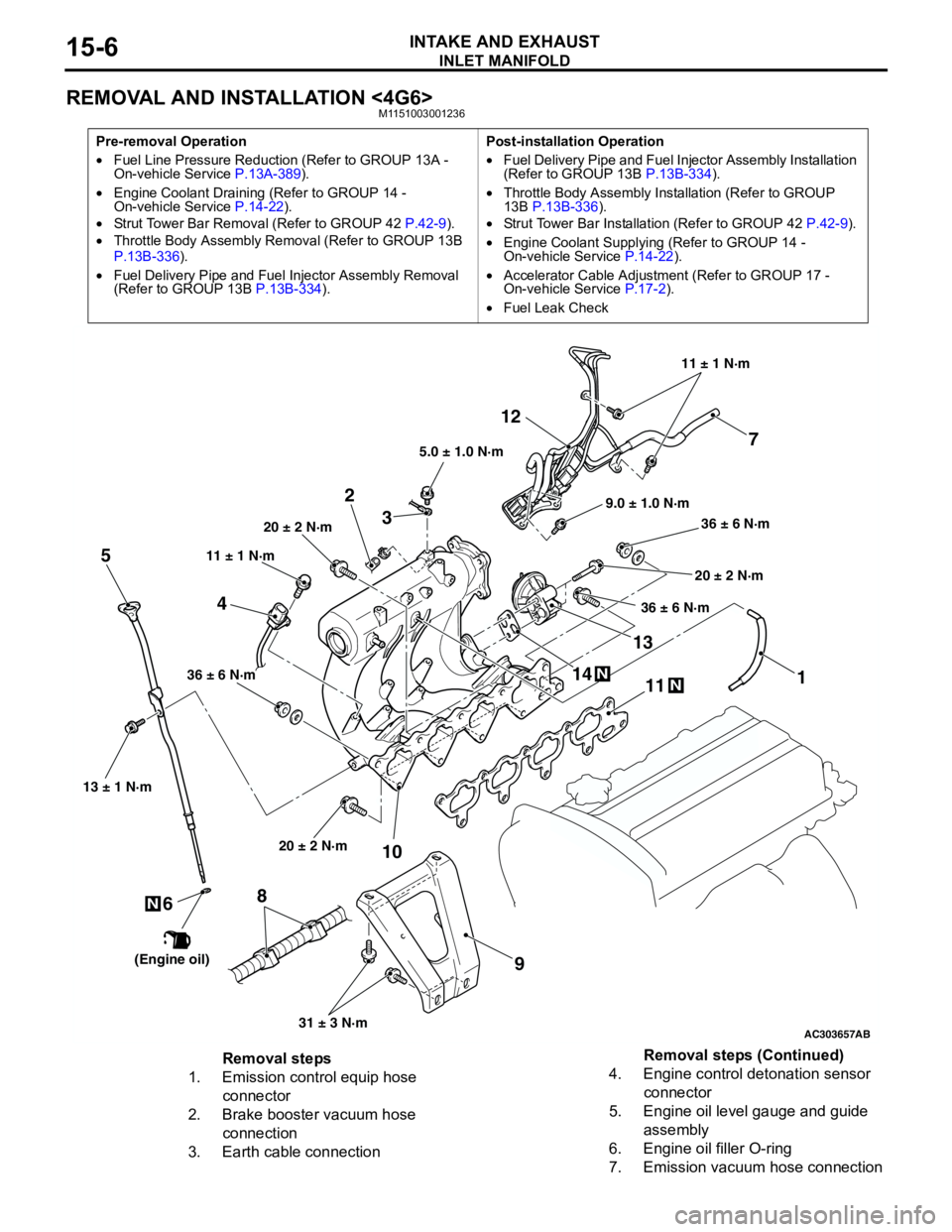
REMOVAL AND INSTALLATION <4G6>M1151003001236
Pre-removal Operation
•Fuel Line Pressure Reduction (Refer to GROUP 13A -
On-vehicle Service P.13A-389).
•Engine Coolant Draining (Refer to GROUP 14 -
On-vehicle Service P.14-22).
•Strut Tower Bar Removal (Refer to GROUP 42 P.42-9).
•Throttle Body Assembly Removal (Refer to GROUP 13B
P.13B-336).
•Fuel Delivery Pipe and Fuel Injector Assembly Removal
(Refer to GROUP 13B P.13B-334).Post-installation Operation
•Fuel Delivery Pipe and Fuel Injector Assembly Installation
(Refer to GROUP 13B P.13B-334).
•Throttle Body Assembly Installation (Refer to GROUP
13B P.13B-336).
•Strut Tower Bar Installation (Refer to GROUP 42 P.42-9).
•Engine Coolant Supplying (Refer to GROUP 14 -
On-vehicle Service P.14-22).
•Accelerator Cable Adjustment (Refer to GROUP 17 -
On-vehicle Service P.17-2).
•Fuel Leak Check
AC303657
9.0 ± 1.0 N·m11 ± 1 N·m
20 ± 2 N·m
31 ± 3 N·m 36 ± 6 N·m
20 ± 2 N·m
20 ± 2 N·m
36 ± 6 N·m
36 ± 6 N·m
11
9 10 212
N1413N
AB
5.0 ± 1.0 N·m
3
1
11 ± 1 N·m
4
N
13 ± 1 N·m
5
6
(Engine oil)
7
8
Removal steps
1. Emission control equip hose
connector
2. Brake booster vacuum hose
connection
3. Earth cable connection4. Engine control detonation sensor
connector
5. Engine oil level gauge and guide
assembly
6. Engine oil filler O-ring
7. Emission vacuum hose connectionRemoval steps (Continued)
Page 69 of 788
CHARGING SYSTEM
ENGINE ELECTRICAL16-5
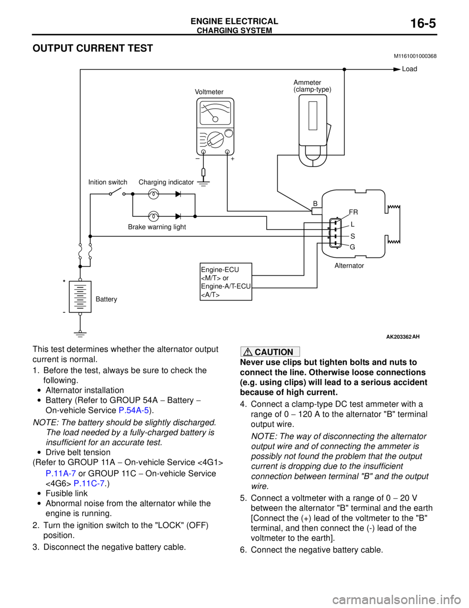
OUTPUT CURRENT TESTM1161001000368
This test determines whether the alternator output
current is normal.
1. Before the test, always be sure to check the
following.
•Alternator installation
•Battery (Refer to GROUP 54A − Battery −
On-vehicle Service P.54A-5).
NOTE: The battery should be slightly discharged.
The load needed by a fully-charged battery is
insufficient for an accurate test.
•Drive belt tension
(Refer to GROUP 11A − On-vehicle Service <4G1>
P.11A-7 or GROUP 11C − On-vehicle Service
<4G6> P.11C-7.)
•Fusible link
•Abnormal noise from the alternator while the
engine is running.
2. Turn the ignition switch to the "LOCK" (OFF)
position.
3. Disconnect the negative battery cable.CAUTION
Never use clips but tighten bolts and nuts to
connect the line. Otherwise loose connections
(e.g. using clips) will lead to a serious accident
because of high current.
4. Connect a clamp-type DC test ammeter with a
range of 0 − 120 A to the alternator "B" terminal
output wire.
NOTE: The way of disconnecting the alternator
output wire and of connecting the ammeter is
possibly not found the problem that the output
current is dropping due to the insufficient
connection between terminal "B" and the output
wire.
5. Connect a voltmeter with a range of 0 − 20 V
between the alternator "B" terminal and the earth
[Connect the (+) lead of the voltmeter to the "B"
terminal, and then connect the (-) lead of the
voltmeter to the earth].
6. Connect the negative battery cable.
AK203362
Alternator Ammeter
(clamp-type)
Voltmeter
Battery Inition switch
Engine-ECU
Engine-A/T-ECU
Load
B
FR
L
S
G +
AH
–
Charging indicator
Brake warning light
Page 139 of 788
ON-VEHICLE SERVICE
FRONT AXLE26-7
ON-VEHICLE SERVICE
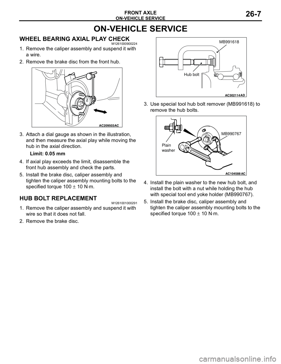
WHEEL BEARING AXIAL PLAY CHECKM1261000900224
1. Remove the caliper assembly and suspend it with
a wire.
2. Remove the brake disc from the front hub.
3. Attach a dial gauge as shown in the illustration,
and then measure the axial play while moving the
hub in the axial direction.
Limit: 0.05 mm
4. If axial play exceeds the limit, disassemble the
front hub assembly and check the parts.
5. Install the brake disc, caliper assembly and
tighten the caliper assembly mounting bolts to the
specified torque 100 ± 10 N⋅m.
HUB BOLT REPLACEMENTM1261001000291
1. Remove the caliper assembly and suspend it with
wire so that it does not fall.
2. Remove the brake disc.3. Use special tool hub bolt remover (MB991618) to
remove the hub bolts.
4. Install the plain washer to the new hub bolt, and
install the bolt with a nut while holding the hub
with special tool end yoke holder (MB990767).
5. Install the brake disc, caliper assembly and
tighten the caliper assembly mounting bolts to the
specified torque 100 ± 10 N⋅m.
AC209503AC
AC302114
MB991618
AD
Hub bolt
AC104588
MB990767
Plain
washer
AC
Page 140 of 788
FRONT AXLE HUB ASSEMBLY
FRONT AXLE26-8
FRONT AXLE HUB ASSEMBLY
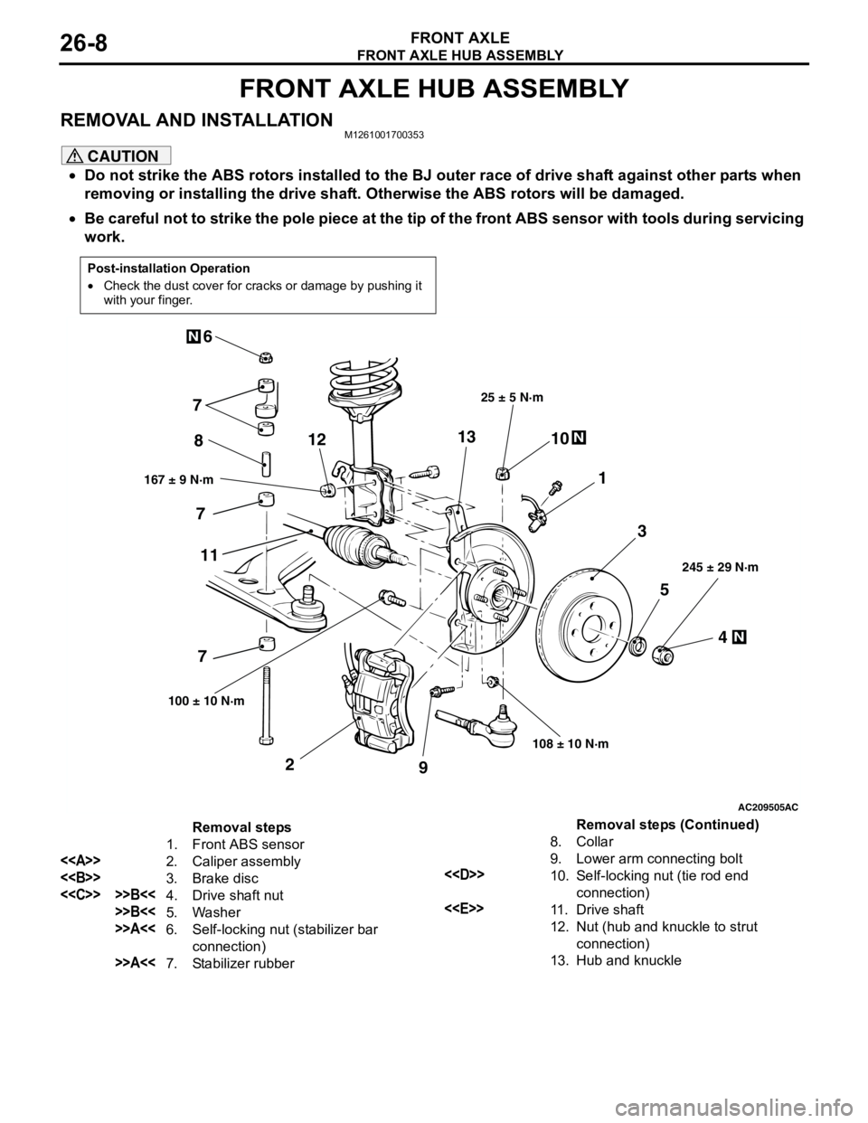
REMOVAL AND INSTALLATIONM1261001700353
CAUTION
•Do not strike the ABS rotors installed to the BJ outer race of drive shaft against other parts when
removing or installing the drive shaft. Otherwise the ABS rotors will be damaged.
•Be careful not to strike the pole piece at the tip of the front ABS sensor with tools during servicing
work.
Post-installation Operation
•Check the dust cover for cracks or damage by pushing it
with your finger.
AC209505
N
N
N
5
4 3 1 810
9 2 76
167 ± 9 N·m25 ± 5 N·m
108 ± 10 N·m245 ± 29 N·m
100 ± 10 N·m
AC
7
7
111213
Removal steps
1. Front ABS sensor
<>
2. Caliper assembly
<>
3. Brake disc
<
>>B<<5. Washer
>>A<<6. Self-locking nut (stabilizer bar
connection)
>>A<<7. Stabilizer rubber8. Collar
9. Lower arm connecting bolt
<
10. Self-locking nut (tie rod end
connection)
<
11 . D r i v e s h a f t
12. Nut (hub and knuckle to strut
connection)
13. Hub and knuckle
Removal steps (Continued)
Page 141 of 788
Page 145 of 788
FRONT AXLE HUB ASSEMBLY
FRONT AXLE26-13
REASSEMBLY SERVICE POINTS
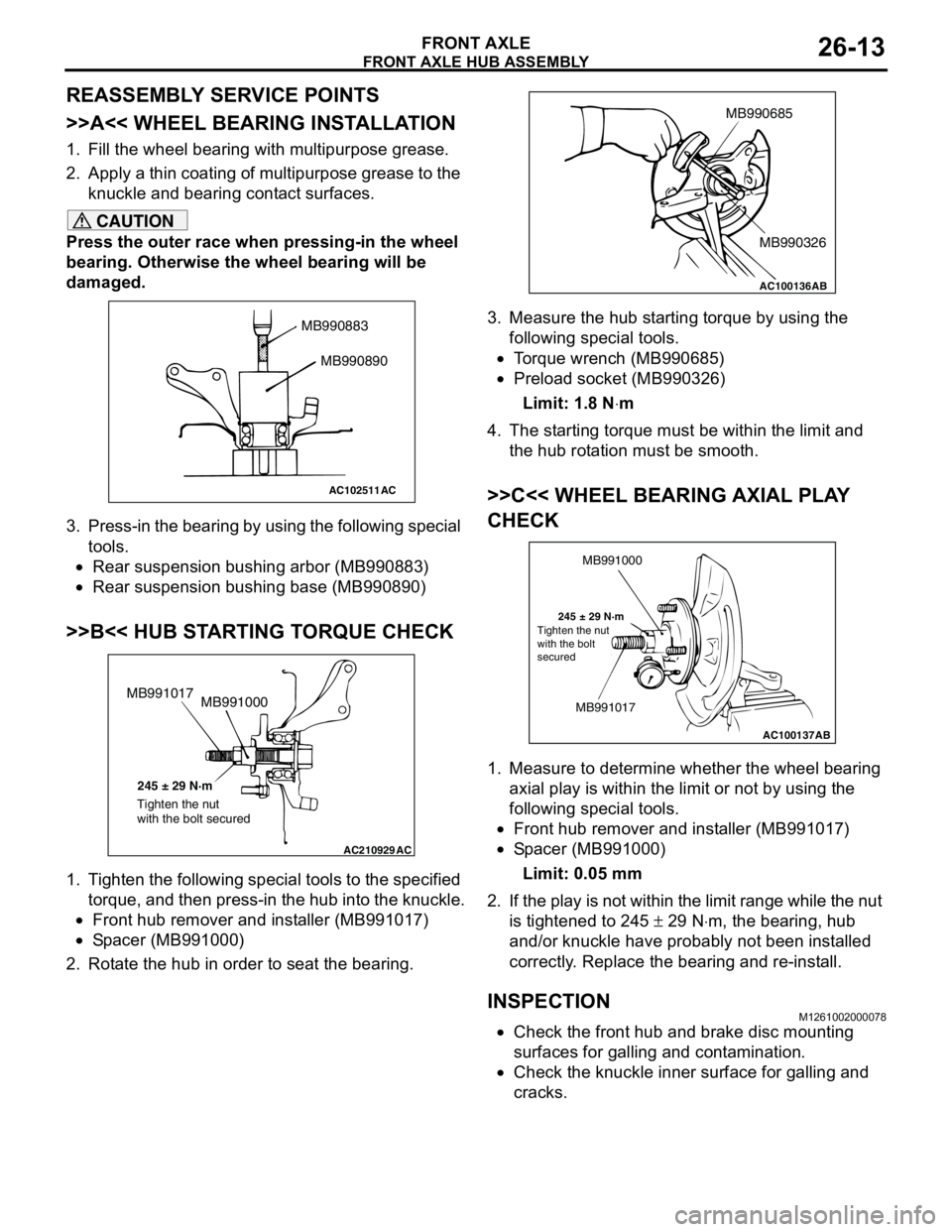
>>A<< WHEEL BEARING INSTALLATION
1. Fill the wheel bearing with multipurpose grease.
2. Apply a thin coating of multipurpose grease to the
knuckle and bearing contact surfaces.
CAUTION
Press the outer race when pressing-in the wheel
bearing. Otherwise the wheel bearing will be
damaged.
3. Press-in the bearing by using the following special
tools.
•Rear suspension bushing arbor (MB990883)
•Rear suspension bushing base (MB990890)
>>B<< HUB STARTING TORQUE CHECK
1. Tighten the following special tools to the specified
torque, and then press-in the hub into the knuckle.
•Front hub remover and installer (MB991017)
•Spacer (MB991000)
2. Rotate the hub in order to seat the bearing.3. Measure the hub starting torque by using the
following special tools.
•Torque wrench (MB990685)
•Preload socket (MB990326)
Limit: 1.8 N⋅m
4. The starting torque must be within the limit and
the hub rotation must be smooth.
>>C<< WHEEL BEARING AXIAL PLAY
CHECK
1. Measure to determine whether the wheel bearing
axial play is within the limit or not by using the
following special tools.
•Front hub remover and installer (MB991017)
•Spacer (MB991000)
Limit: 0.05 mm
2. If the play is not within the limit range while the nut
is tightened to 245 ± 29 N⋅m, the bearing, hub
and/or knuckle have probably not been installed
correctly. Replace the bearing and re-install.
INSPECTIONM1261002000078
•Check the front hub and brake disc mounting
surfaces for galling and contamination.
•Check the knuckle inner surface for galling and
cracks.
AC102511
MB990883
MB990890
AC
AC210929AC
MB991000 MB991017
245 ± 29 N·m
Tighten the nut
with the bolt secured
AC100136
MB990685
MB990326
AB
AC100137
MB991000
MB991017
245 ± 29 N·m
AB Tighten the nut
with the bolt
secured
Page 146 of 788
DRIVE SHAFT ASSEMBLY
FRONT AXLE26-14
DRIVE SHAFT ASSEMBLY
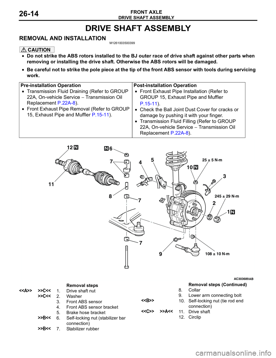
REMOVAL AND INSTALLATIONM1261003500399
CAUTION
•Do not strike the ABS rotors installed to the BJ outer race of drive shaft against other parts when
removing or installing the drive shaft. Otherwise the ABS rotors will be damaged.
•Be careful not to strike the pole piece at the tip of the front ABS sensor with tools during servicing
work.
Pre-installation Operation
•Transmission Fluid Draining (Refer to GROUP
22A, On-vehicle Service − Transmission Oil
Replacement P.22A-8).
•Front Exhaust Pipe Removal (Refer to GROUP
15, Exhaust Pipe and Muffler P.15-11).Post-installation Operation
•Front Exhaust Pipe Installation (Refer to
GROUP 15, Exhaust Pipe and Muffler
P.15-11).
•Check the Ball Joint Dust Cover for cracks or
damage by pushing it with your finger.
•Transmission Fluid Filling (Refer to GROUP
22A, On-vehicle Service − Transmission Oil
Replacement P.22A-8).
AC303689AB
9
N
N
NN
10 7
4
3
2
1
25 ± 5 N·m
245 ± 29 N·m
108 ± 10 N·m
8
5 6
1112
7
7
Removal steps
<> >>C<<1. Drive shaft nut
>>C<<2. Washer
3. Front ABS sensor
4. Front ABS sensor bracket
5. Brake hose bracket
>>B<<6. Self-locking nut (stabilizer bar
connection)
>>B<<7. Stabilizer rubber8. Collar
9. Lower arm connecting bolt
<>10. Self-locking nut (tie rod end
connection)
<
12. CirclipRemoval steps (Continued)
Page 147 of 788
