Rake MITSUBISHI LANCER 2005 Owner's Manual
[x] Cancel search | Manufacturer: MITSUBISHI, Model Year: 2005, Model line: LANCER, Model: MITSUBISHI LANCER 2005Pages: 788, PDF Size: 45.98 MB
Page 230 of 788
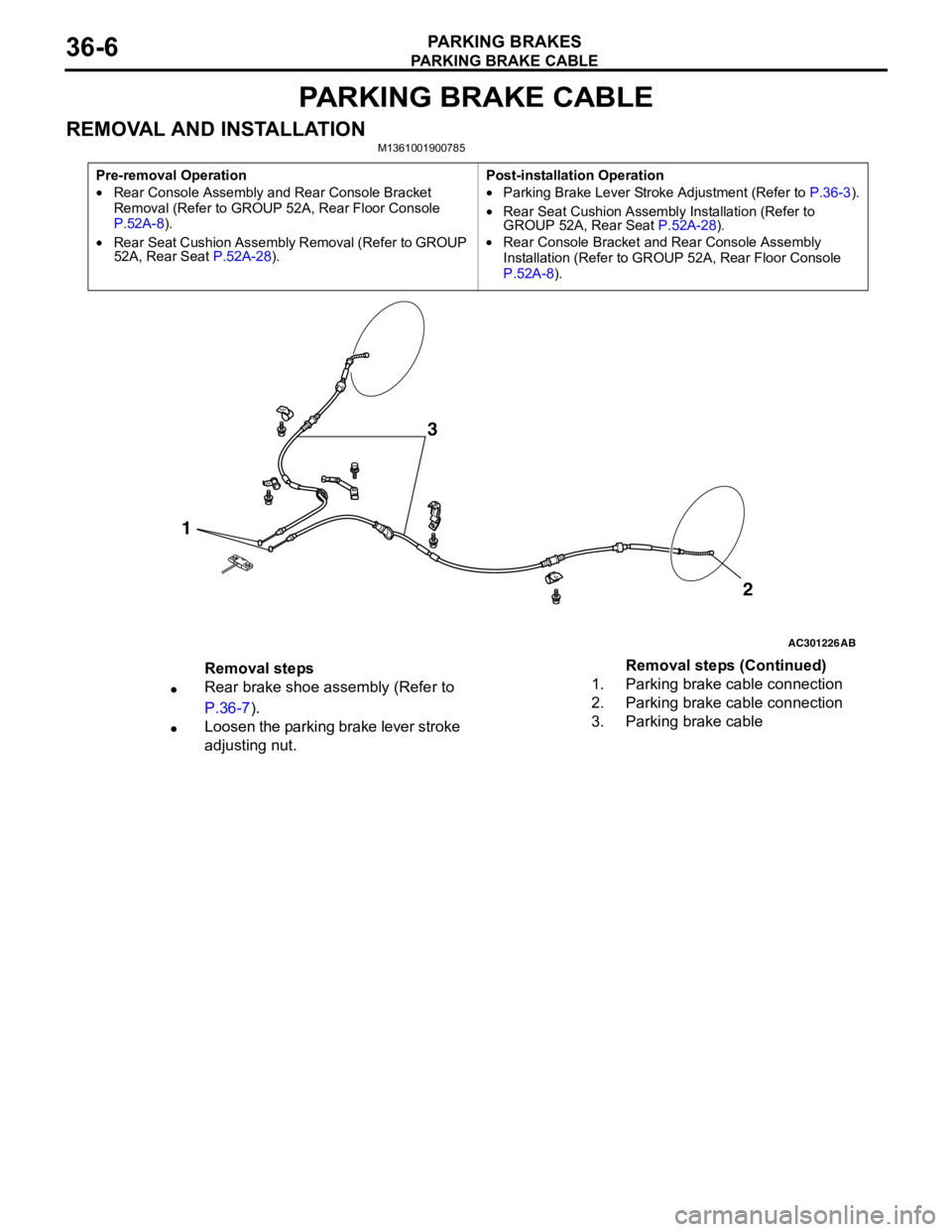
PARKING BRAKE CABLE
PARKING BRAKES36-6
PARKING BRAKE CABLE
REMOVAL AND INSTALLATIONM1361001900785
Pre-removal Operation
•Rear Console Assembly and Rear Console Bracket
Removal (Refer to GROUP 52A, Rear Floor Console
P.52A-8).
•Rear Seat Cushion Assembly Removal (Refer to GROUP
52A, Rear Seat P.52A-28).Post-installation Operation
•Parking Brake Lever Stroke Adjustment (Refer to P.36-3).
•Rear Seat Cushion Assembly Installation (Refer to
GROUP 52A, Rear Seat P.52A-28).
•Rear Console Bracket and Rear Console Assembly
Installation (Refer to GROUP 52A, Rear Floor Console
P.52A-8).
AC301226
1
AB
2
3
Removal steps
•Rear brake shoe assembly (Refer to
P.36-7).
•Loosen the parking brake lever stroke
adjusting nut.1. Parking brake cable connection
2. Parking brake cable connection
3. Parking brake cableRemoval steps (Continued)
Page 231 of 788
PARKING BRAKE LINING AND DRUM
PARKING BRAKES36-7
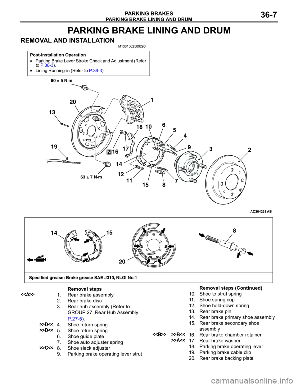
PARKING BRAKE LINING AND DRUM
REMOVAL AND INSTALLATIONM1361002500296
Post-installation Operation
•Parking Brake Lever Stroke Check and Adjustment (Refer
to P.36-3).
•Lining Running-in (Refer to P.36-3).
AC304238
19
60 ± 5 N·m
63 ± 7 N·m
AB
13
4
155
3
89
72 1
6
10
11 121718
14 16 20
N
15
14
208
Specified grease: Brake grease SAE J310, NLGI No.1
Removal steps
<>
1. Rear brake assembly
2. Rear brake disc
3. Rear hub assembly (Refer to
GROUP 27, Rear Hub Assembly
P.27-5).
>>D<<4. Shoe return spring
>>D<<5. Shoe return spring
6. Shoe guide plate
7. Shoe auto adjuster spring
>>C<<8. Shoe slack adjuster
9. Parking brake operating lever strut
10. Shoe to strut spring
11. Shoe spring cup
12. Shoe hold-down spring
13. Rear brake pin
14. Rear brake primary shoe assembly
15. Rear brake secondary shoe
assembly
<> >>B<<16. Rear brake chamber retainer
>>A<<17. Rear brake washer
18. Parking brake operating lever
19. Parking brake cable clip
20. Rear brake backing plate
Removal steps (Continued)
Page 232 of 788
Page 233 of 788
PARKING BRAKE LINING AND DRUM
PARKING BRAKES36-9
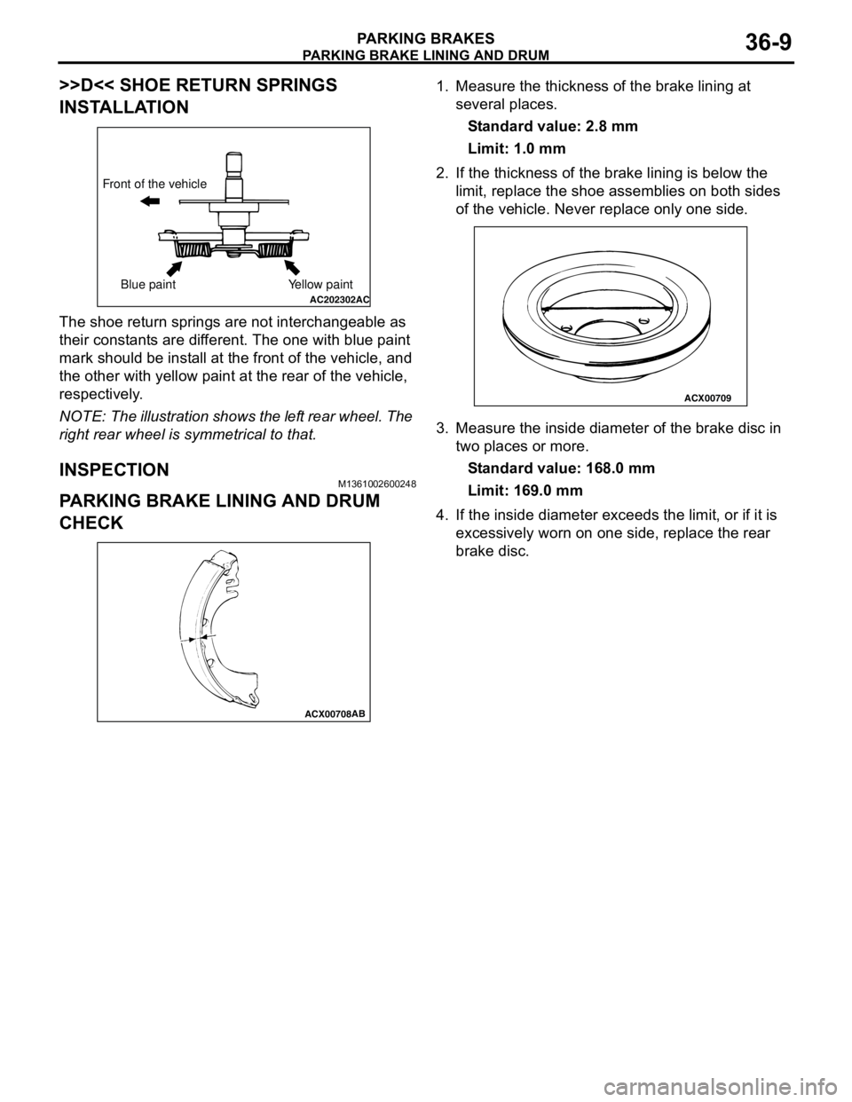
>>D<< SHOE RETURN SPRINGS
INSTALLATION
The shoe return springs are not interchangeable as
their constants are different. The one with blue paint
mark should be install at the front of the vehicle, and
the other with yellow paint at the rear of the vehicle,
respectively.
NOTE: The illustration shows the left rear wheel. The
right rear wheel is symmetrical to that.
INSPECTIONM1361002600248
PARKING BRAKE LINING AND DRUM
CHECK
1. Measure the thickness of the brake lining at
several places.
Standard value: 2.8 mm
Limit: 1.0 mm
2. If the thickness of the brake lining is below the
limit, replace the shoe assemblies on both sides
of the vehicle. Never replace only one side.
3. Measure the inside diameter of the brake disc in
two places or more.
Standard value: 168.0 mm
Limit: 169.0 mm
4. If the inside diameter exceeds the limit, or if it is
excessively worn on one side, replace the rear
brake disc.
AC202302AC
Front of the vehicle
Blue paint Yellow paint
ACX00708AB
ACX00709
Page 595 of 788
Page 614 of 788
ENGINE AND TRANSMISSION
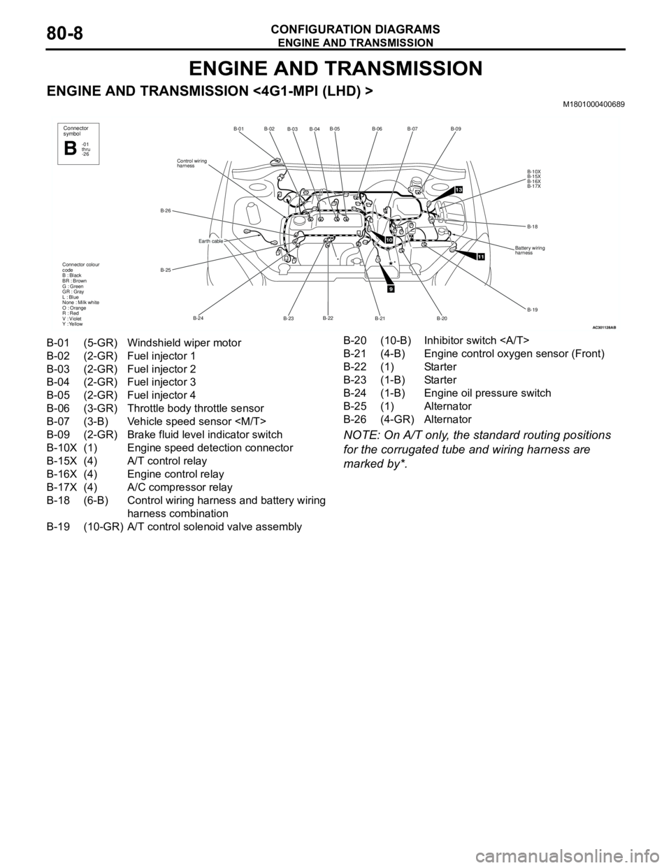
CONFIGURATION DIAGRAMS80-8
ENGINE AND TRANSMISSION
ENGINE AND TRANSMISSION <4G1-MPI (LHD) >M1801000400689
NOTE: On A/T only, the standard routing positions
for the corrugated tube and wiring harness are
marked by*.
AC301128
B-02
B-03B-04B-05
B-22
B-23 B-24 B-25 B-26Control wiring
harnessB-01
Connector colour
code
B : Black
BR : Brown
G : Green
GR : Gray
L : Blue
None : Milk white
O : Orange
R : Red
V : Violet
Y : Yellow*
Connector
symbol
-01
thru
-26B
Earth cable
AB
9
10
11
13
B-06B-07
B-09
B-10X
B-15X
B-16X
B-17X
B-18
Battery wiring
harness
B-19
B-20
B-21
*
B-01 (5-GR) Windshield wiper motor
B-02 (2-GR) Fuel injector 1
B-03 (2-GR) Fuel injector 2
B-04 (2-GR) Fuel injector 3
B-05 (2-GR) Fuel injector 4
B-06 (3-GR) Throttle body throttle sensor
B-07 (3-B) Vehicle speed sensor
B-09 (2-GR) Brake fluid level indicator switch
B-10X (1) Engine speed detection connector
B-15X (4) A/T control relay
B-16X (4) Engine control relay
B-17X (4) A/C compressor relay
B-18 (6-B) Control wiring harness and battery wiring
harness combination
B-19 (10-GR) A/T control solenoid valve assemblyB-20 (10-B) Inhibitor switch
B-21 (4-B) Engine control oxygen sensor (Front)
B-22 (1) Starter
B-23 (1-B) Starter
B-24 (1-B) Engine oil pressure switch
B-25 (1) Alternator
B-26 (4-GR) Alternator
Page 616 of 788
ENGINE AND TRANSMISSION
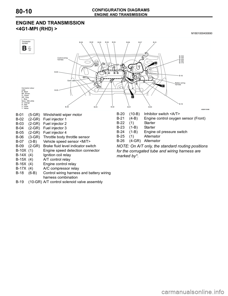
CONFIGURATION DIAGRAMS80-10
ENGINE AND TRANSMISSION
<4G1-MPI (RHD) >
M1801000400690
NOTE: On A/T only, the standard routing positions
for the corrugated tube and wiring harness are
marked by*.
AC301131
B-02
B-03B-04 B-05
B-22
B-23 B-24 B-25 B-26Control wiring
harnessB-09
Connector colour
code
B : Black
BR : Brown
G : Green
GR : Gray
L : Blue
None : Milk white
O : Orange
R : Red
V : Violet
Y : Yellow*
Connector
symbol
-01
thru
-26B
Earth cable
AB
9
10
11
13
B-06B-07
B-01
B-10X
B-14X
B-15X
B-16X
B-17X
B-18
Battery wiring
harness
B-19
B-20 B-21
*
B-01 (5-GR) Windshield wiper motor
B-02 (2-GR) Fuel injector 1
B-03 (2-GR) Fuel injector 2
B-04 (2-GR) Fuel injector 3
B-05 (2-GR) Fuel injector 4
B-06 (3-GR) Throttle body throttle sensor
B-07 (3-B) Vehicle speed sensor
B-09 (2-GR) Brake fluid level indicator switch
B-10X (1) Engine speed detection connector
B-14X (4) Ignition coil relay
B-15X (4) A/T control relay
B-16X (4) Engine control relay
B-17X (4) A/C compressor relay
B-18 (6-B) Control wiring harness and battery wiring
harness combination
B-19 (10-GR) A/T control solenoid valve assemblyB-20 (10-B) Inhibitor switch
B-21 (4-B) Engine control oxygen sensor (Front)
B-22 (1) Starter
B-23 (1-B) Starter
B-24 (1-B) Engine oil pressure switch
B-25 (1) Alternator
B-26 (4-GR) Alternator
Page 618 of 788
ENGINE AND TRANSMISSION
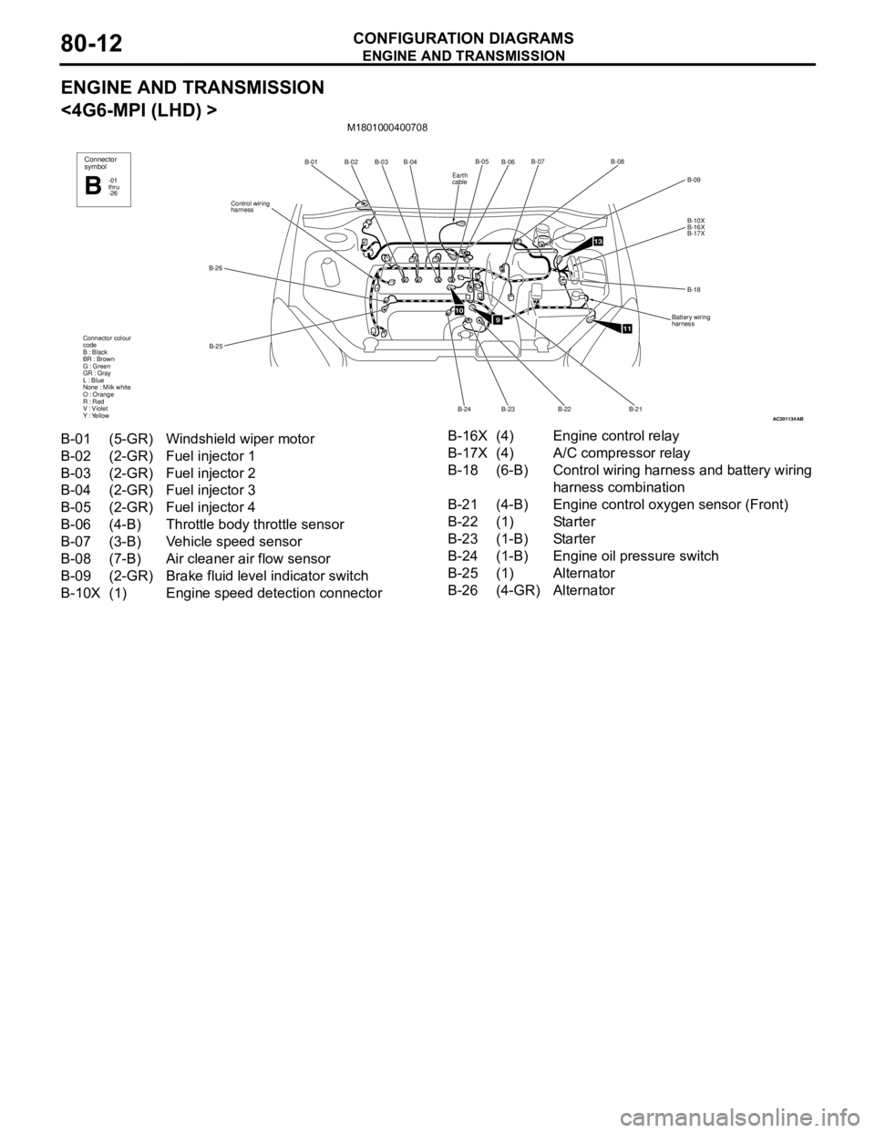
CONFIGURATION DIAGRAMS80-12
ENGINE AND TRANSMISSION
<4G6-MPI (LHD) >
M1801000400708
AC301134
B-02
B-03B-04
B-25 B-26Control wiring
harnessB-01
Connector colour
code
B : Black
BR : Brown
G : Green
GR : Gray
L : Blue
None : Milk white
O : Orange
R : Red
V : Violet
Y : YellowConnector
symbol
-01
thru
-26B
AB
910
11
13
B-06B-07
B-09
B-10X
B-16X
B-17X
B-18
Battery wiring
harness
B-21 B-22
B-23B-05B-08
B-24
Earth
cable
B-01 (5-GR) Windshield wiper motor
B-02 (2-GR) Fuel injector 1
B-03 (2-GR) Fuel injector 2
B-04 (2-GR) Fuel injector 3
B-05 (2-GR) Fuel injector 4
B-06 (4-B) Throttle body throttle sensor
B-07 (3-B) Vehicle speed sensor
B-08 (7-B) Air cleaner air flow sensor
B-09 (2-GR) Brake fluid level indicator switch
B-10X (1) Engine speed detection connectorB-16X (4) Engine control relay
B-17X (4) A/C compressor relay
B-18 (6-B) Control wiring harness and battery wiring
harness combination
B-21 (4-B) Engine control oxygen sensor (Front)
B-22 (1) Starter
B-23 (1-B) Starter
B-24 (1-B) Engine oil pressure switch
B-25 (1) Alternator
B-26 (4-GR) Alternator
Page 620 of 788
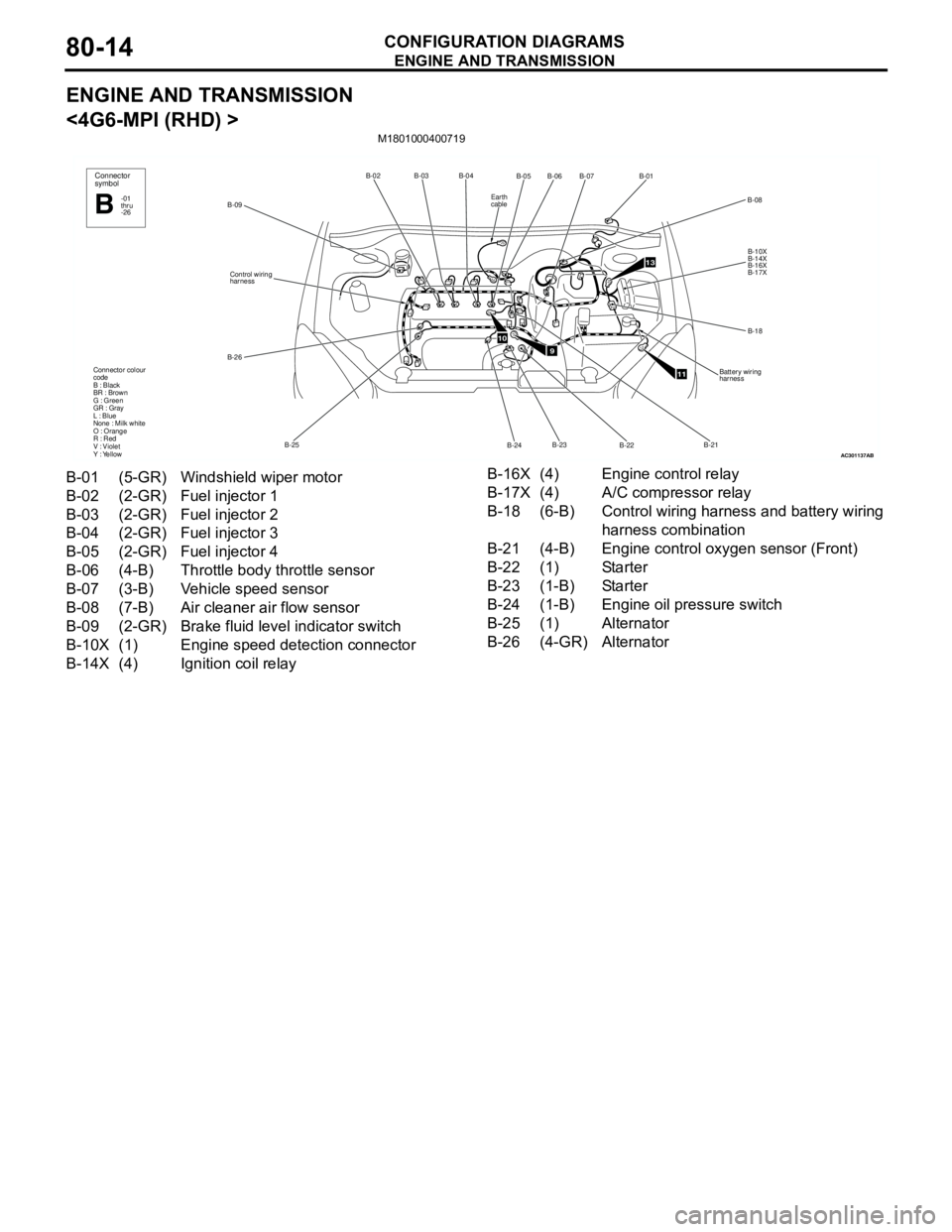
ENGINE AND TRANSMISSION
CONFIGURATION DIAGRAMS80-14
ENGINE AND TRANSMISSION
<4G6-MPI (RHD) >
M1801000400719
AC301137
B-02B-03B-04
B-25 B-26Control wiring
harness
B-09
Connector colour
code
B : Black
BR : Brown
G : Green
GR : Gray
L : Blue
None : Milk white
O : Orange
R : Red
V : Violet
Y : Yellow
Connector
symbol
-01
thru
-26B
AB
910
11
13
B-05
B-07B-01
B-10X
B-14X
B-16X
B-17X
B-18
Battery wiring
harness
B-22 B-24B-06
B-08
B-23B-21
Earth
cable
B-01 (5-GR) Windshield wiper motor
B-02 (2-GR) Fuel injector 1
B-03 (2-GR) Fuel injector 2
B-04 (2-GR) Fuel injector 3
B-05 (2-GR) Fuel injector 4
B-06 (4-B) Throttle body throttle sensor
B-07 (3-B) Vehicle speed sensor
B-08 (7-B) Air cleaner air flow sensor
B-09 (2-GR) Brake fluid level indicator switch
B-10X (1) Engine speed detection connector
B-14X (4) Ignition coil relayB-16X (4) Engine control relay
B-17X (4) A/C compressor relay
B-18 (6-B) Control wiring harness and battery wiring
harness combination
B-21 (4-B) Engine control oxygen sensor (Front)
B-22 (1) Starter
B-23 (1-B) Starter
B-24 (1-B) Engine oil pressure switch
B-25 (1) Alternator
B-26 (4-GR) Alternator
Page 628 of 788
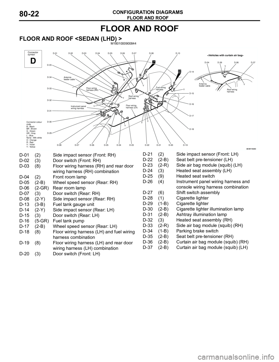
FLOOR AND ROOF
CONFIGURATION DIAGRAMS80-22
FLOOR AND ROOF
FLOOR AND ROOF
AC301155
D-06
D-07
D-05 D-04 D-03 D-02 D-01
D-35
D-34
D-33
D-32
D-31
D-30
D-29
D-25
D-28D-27 D-24
D-23 Y
Y
YFloor wiring
harness (LH) Floor wiring
harness (RH)
Instrument panel
wiring harnessConnector
symbol
D
D-26
Roof wiring
harness
Connector colour
code
B : Black
BR : Brown
G : Green
GR : Gray
L : Blue
None : Milk white
O : Orange
R : Red
V : Violet
Y : Yellow
Antenna
feeder cable
D-08
D-13
D-14
D-15
D-16
D-17
D-18
D-19 D-20
D-21 D-22Y
YFuel wiring
harness
7
17
Y
Y
AC
Y
Y D-04 D-36 D-06 D-37
Roof wiring
harness
Antenna
feeder cable
D-01 (2) Side impact sensor (Front: RH)
D-02 (3) Door switch (Front: RH)
D-03 (8) Floor wiring harness (RH) and rear door
wiring harness (RH) combination
D-04 (2) Front room lamp
D-05 (2-B) Wheel speed sensor (Rear: RH)
D-06 (2-GR) Rear room lamp
D-07 (3) Door switch (Rear: RH)
D-08 (2-Y) Side impact sensor (Rear: RH)
D-13 (3-B) Fuel tank gauge unit
D-14 (2-Y) Side impact sensor (Rear: LH)
D-15 (3) Door switch (Rear: LH)
D-16 (5-GR) Fuel tank pump
D-17 (2-B) Wheel speed sensor (Rear: LH)
D-18 (8) Floor wiring harness (LH) and fuel wiring
harness combination
D-19 (8) Floor wiring harness (LH) and rear door
wiring harness (LH) combination
D-20 (3) Door switch (Front: LH)D-21 (2) Side impact sensor (Front: LH)
D-22 (2-B) Seat belt pre-tensioner (LH)
D-23 (2-R) Side air bag module (squib) (LH)
D-24 (3) Heated seat assembly (LH)
D-25 (9) Heated seat switch
D-26 (4) Instrument panel wiring harness and
console wiring harness combination
D-27 (6) Shift switch assembly
D-28 (1) Cigarette lighter
D-29 (1-B) Cigarette lighter
D-30 (2-B) Cigarette lighter illumination lamp
D-31 (2-B) Ashtray illumination lamp
D-32 (3) Heated seat assembly (RH)
D-33 (2-R) Side air bag module (squib) (RH)
D-34 (1-B) Parking brake switch
D-35 (2-B) Seat belt pre-tensioner (RH)
D-36 (2-B) Curtain air bag module (squib) (RH)
D-37 (2-B) Curtain air bag module (squib) (LH)