charging MITSUBISHI LANCER 2005 User Guide
[x] Cancel search | Manufacturer: MITSUBISHI, Model Year: 2005, Model line: LANCER, Model: MITSUBISHI LANCER 2005Pages: 788, PDF Size: 45.98 MB
Page 75 of 788
CHARGING SYSTEM
ENGINE ELECTRICAL16-11
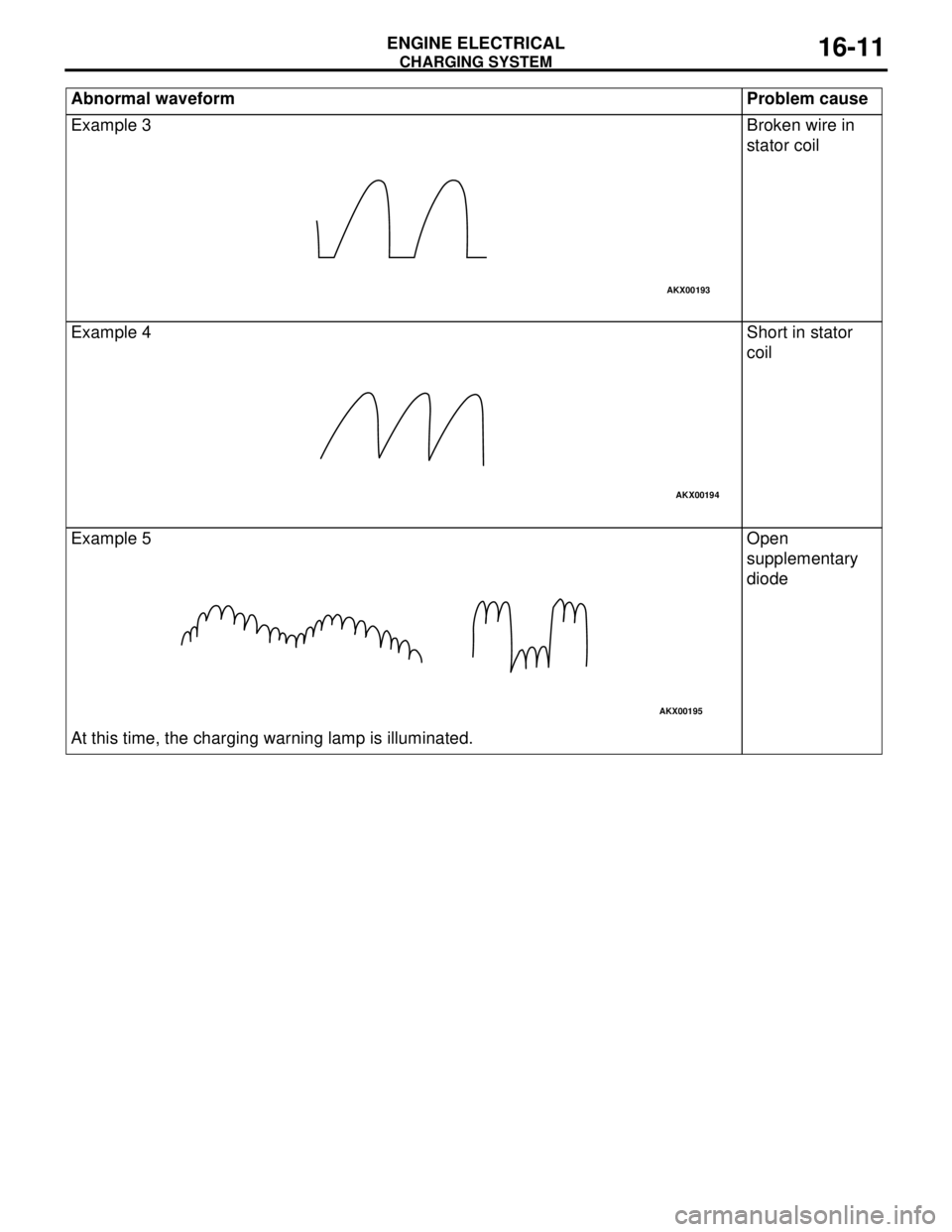
Example 3 Broken wire in
stator coil
Example 4 Short in stator
coil
Example 5
At this time, the charging warning lamp is illuminated.Open
supplementary
diode Abnormal waveform Problem cause
AKX00193
AKX00194
AKX00195
Page 76 of 788
CHARGING SYSTEM
ENGINE ELECTRICAL16-12
ALTERNATOR ASSEMBLY
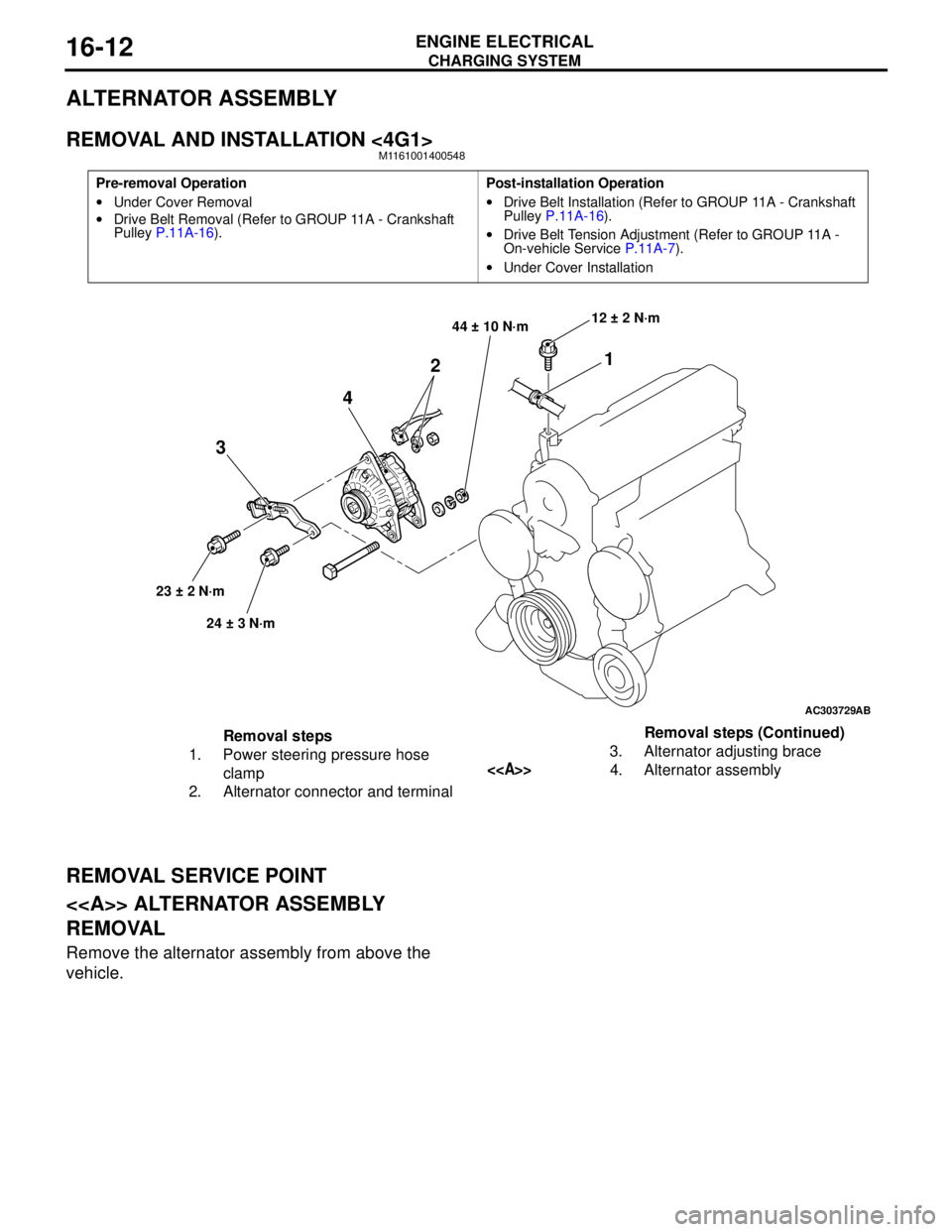
REMOVAL AND INSTALLATION <4G1>M1161001400548
REMOVAL SERVICE POINT
<> ALTERNATOR ASSEMBLY
REMOVAL
Remove the alternator assembly from above the
vehicle.
Pre-removal Operation
•Under Cover Removal
•Drive Belt Removal (Refer to GROUP 11A - Crankshaft
Pulley P.11A-16).Post-installation Operation
•Drive Belt Installation (Refer to GROUP 11A - Crankshaft
Pulley P.11A-16).
•Drive Belt Tension Adjustment (Refer to GROUP 11A -
On-vehicle Service P.11A-7).
•Under Cover Installation
AC303729
1
2
4
3
44 ± 10 N·m
23 ± 2 N·m
24 ± 3 N·m12 ± 2 N·m
AB
Removal steps
1. Power steering pressure hose
clamp
2. Alternator connector and terminal3. Alternator adjusting brace
<>4. Alternator assemblyRemoval steps (Continued)
Page 77 of 788
CHARGING SYSTEM
ENGINE ELECTRICAL16-13
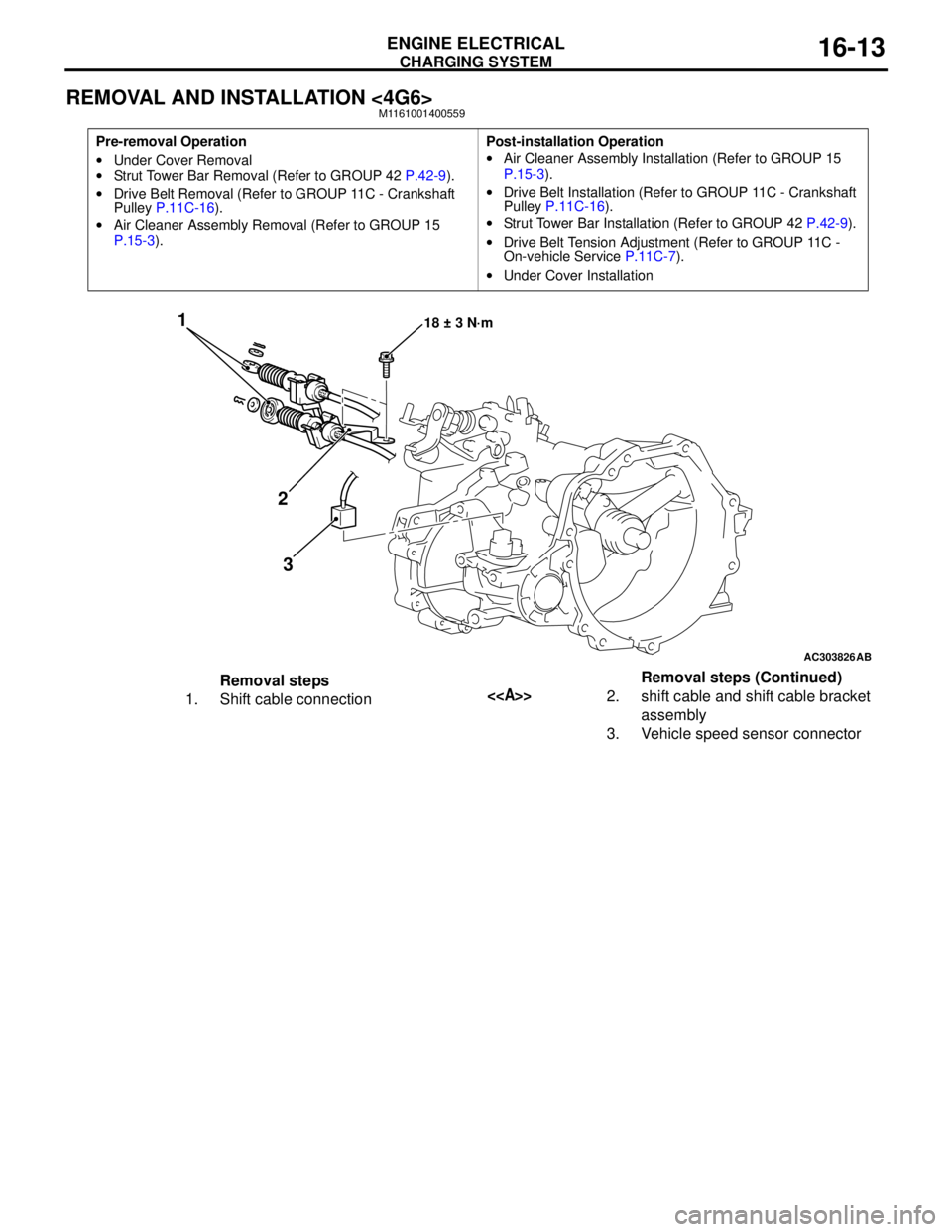
REMOVAL AND INSTALLATION <4G6>M1161001400559
Pre-removal Operation
•Under Cover Removal
•Strut Tower Bar Removal (Refer to GROUP 42 P.42-9).
•Drive Belt Removal (Refer to GROUP 11C - Crankshaft
Pulley P.11C-16).
•Air Cleaner Assembly Removal (Refer to GROUP 15
P.15-3).Post-installation Operation
•Air Cleaner Assembly Installation (Refer to GROUP 15
P.15-3).
•Drive Belt Installation (Refer to GROUP 11C - Crankshaft
Pulley P.11C-16).
•Strut Tower Bar Installation (Refer to GROUP 42 P.42-9).
•Drive Belt Tension Adjustment (Refer to GROUP 11C -
On-vehicle Service P.11C-7).
•Under Cover Installation
AC303826
1
2
318 ± 3 N·m
AB
Removal steps
1. Shift cable connection<>2. shift cable and shift cable bracket
assembly
3. Vehicle speed sensor connectorRemoval steps (Continued)
Page 78 of 788
Page 79 of 788
CHARGING SYSTEM
ENGINE ELECTRICAL16-15
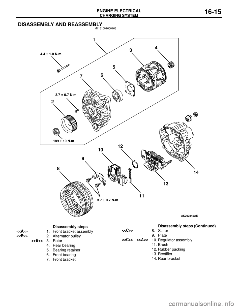
DISASSEMBLY AND REASSEMBLYM1161001600166
AK202845
1
234
5
6
7
8910
11 12
1314
AE
4.4 ± 1.0 N·m
3.7 ± 0.7 N·m
189 ± 19 N·m
3.7 ± 0.7 N·m
Disassembly steps
<>1. Front bracket assembly
<>2. Alternator pulley
>>B<<3. Rotor
4. Rear bearing
5. Bearing retainer
6. Front bearing
7. Front bracket
<
9. Plate
<
11 . B r u s h
12. Rubber packing
13. Rectifier
14. Rear bracketDisassembly steps (Continued)
Page 80 of 788
Page 81 of 788
CHARGING SYSTEM
ENGINE ELECTRICAL16-17
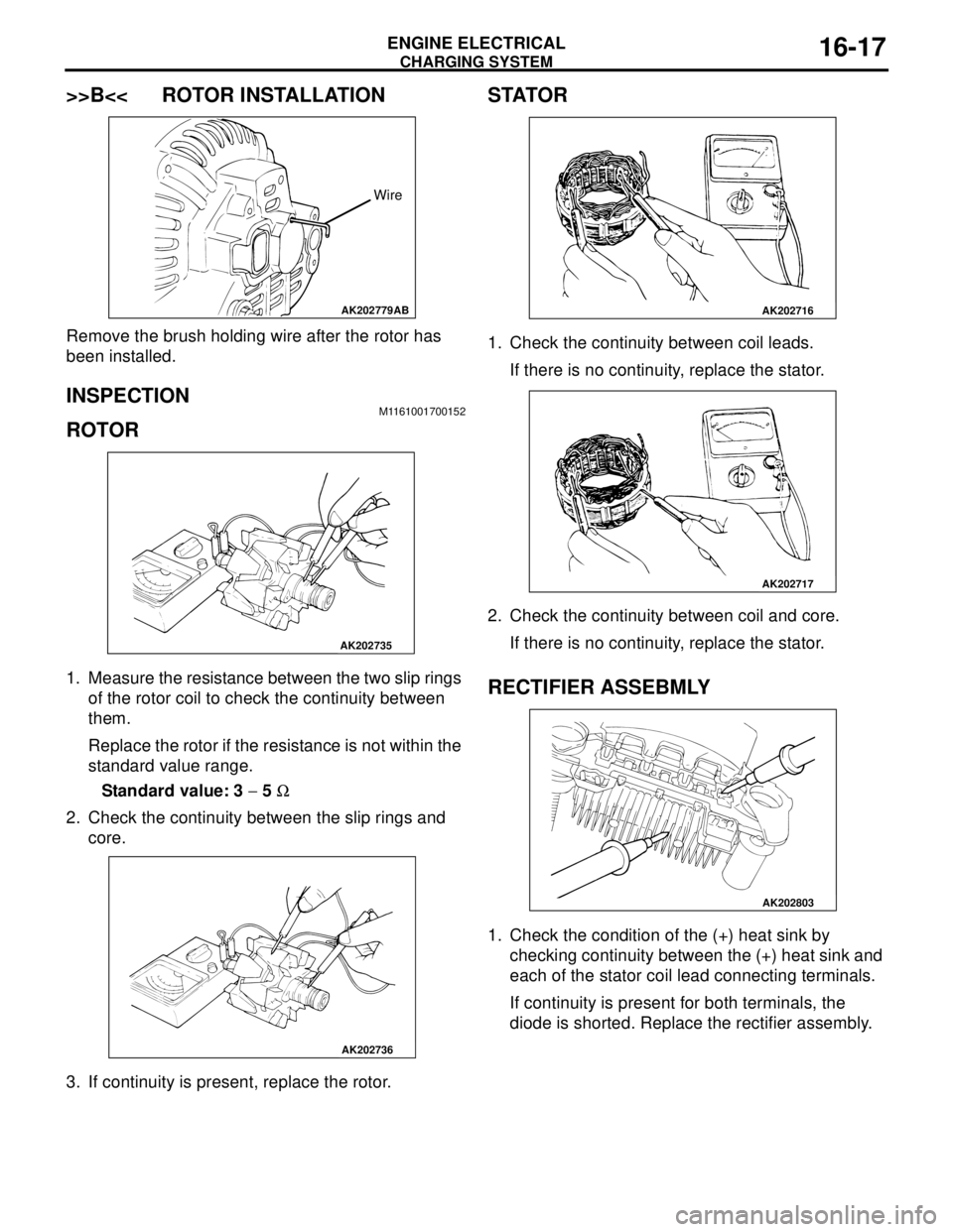
>>B<< ROTOR INSTALLATION
Remove the brush holding wire after the rotor has
been installed.
INSPECTION M1161001700152
ROTOR
1. Measure the resistance between the two slip rings
of the rotor coil to check the continuity between
them.
Replace the rotor if the resistance is not within the
standard value range.
Standard value: 3 − 5 Ω
2. Check the continuity between the slip rings and
core.
3. If continuity is present, replace the rotor.
STATOR
1. Check the continuity between coil leads.
If there is no continuity, replace the stator.
2. Check the continuity between coil and core.
If there is no continuity, replace the stator.
RECTIFIER ASSEBMLY
1. Check the condition of the (+) heat sink by
checking continuity between the (+) heat sink and
each of the stator coil lead connecting terminals.
If continuity is present for both terminals, the
diode is shorted. Replace the rectifier assembly.
AK202779
Wire
AB
AK202735
AK202736
AK202716
AK202717
AK202803
Page 82 of 788
CHARGING SYSTEM
ENGINE ELECTRICAL16-18
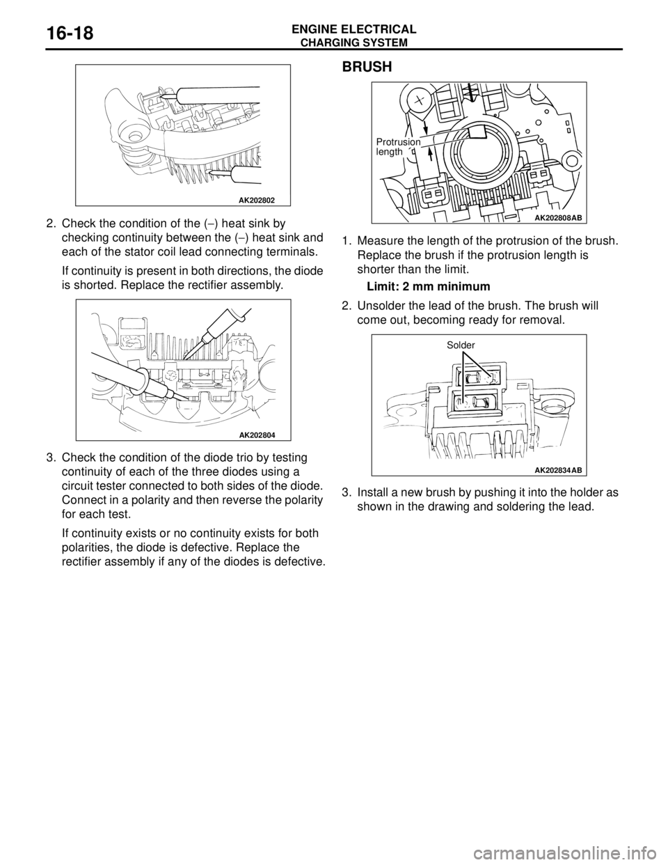
2. Check the condition of the (−) heat sink by
checking continuity between the (−) heat sink and
each of the stator coil lead connecting terminals.
If continuity is present in both directions, the diode
is shorted. Replace the rectifier assembly.
3. Check the condition of the diode trio by testing
continuity of each of the three diodes using a
circuit tester connected to both sides of the diode.
Connect in a polarity and then reverse the polarity
for each test.
If continuity exists or no continuity exists for both
polarities, the diode is defective. Replace the
rectifier assembly if any of the diodes is defective.
BRUSH
1. Measure the length of the protrusion of the brush.
Replace the brush if the protrusion length is
shorter than the limit.
Limit: 2 mm minimum
2. Unsolder the lead of the brush. The brush will
come out, becoming ready for removal.
3. Install a new brush by pushing it into the holder as
shown in the drawing and soldering the lead.
AK202802
AK202804
AK202808
Protrusion
length
AB
AK202834
Solder
AB
Page 389 of 788
54A-1
GROUP 54A
CHASSIS
ELECTRICAL
CONTENTS
BATTERY. . . . . . . . . . . . . . . . . .
54A-4
SERVICE SPECIFICATIONS. . . . .
54A-4
ON-VEHICLE SERVICE. . . . . . . . .54A-4
FLUID LEVEL AND SPECIFIC
GRAVITY CHECK . . . . . . . . . . . . . . . . . 54A-4
CHARGING . . . . . . . . . . . . . . . . . . . . . . 54A-4
BATTERY TEST . . . . . . . . . . . . . . . . . . 54A-5
IGNITION SWITCH* . . . . . . . . . .54A-6
GENERAL INFORMATION . . . . . .
54A-6
SPECIAL TOOLS. . . . . . . . . . . . . .54A-8
TROUBLESHOOTING . . . . . . . . . .54A-9
IGNITION KEY REMINDER BUZZER AND
DOOR LOCK PREVENTION FUNCTION
TROUBLESHOOTING . . . . . . . . . . . . . . 54A-9
IMMOBILIZER SYSTEM
TROUBLESHOOTING . . . . . . . . . .
54A-9
DIAGNOSIS CODE CHART . . . . . . . . . . 54A-9
DIAGNOSTIC TROUBLE CODE
PROCEDURES . . . . . . . . . . . . . . . .
54A-10
SYMPTOM CHART. . . . . . . . . . . . .54A-11
SYMPTOM PROCEDURES . . . . . .54A-12
DATA LIST REFERENCE TABLE .54A-19
CHECK IMMOBILIZER-ECU . . . . .54A-19
ON-VEHICLE SERVICE . . . . . . . . .54A-20
HOW TO REGISTER ENCRYPTED
CODE . . . . . . . . . . . . . . . . . . . . . . . . . . . 54A-20
IGNITION SWITCH . . . . . . . . . . . . . . . . 54A-27
REMOVAL AND INSTALLATION . . . . . . 54A-27
INSPECTION . . . . . . . . . . . . . . . . . . . . . 54A-28
Continued on next page
WARNINGS REGARDING SERVICING OF SUPPLEMENTAL RESTRAINT SYSTEM (SRS) EQUIPPED VEHICLES
WARNING
•Improper service or maintenance of any component of the SRS, or any SRS-related component, can lead to
personal injury or death to service personnel (from inadvertent firing of the air bag) or to the driver and
paassenger (from rendering the SRS inoperative).
•Service or maintenance of any SRS component or SRS-related component must be performed only at an
authorized MITSUBISHI dealer.
•MITSUBISHI dealer personnel must thoroughly review this manual, and especially its GROUP 52B - Supplemental
Restraint System (SRS) before beginning any service or maintenance of any component of the SRS or any
SRS-related component.
NOTE
The SRS includes the following components: SRS air bag control unit, SRS warning light, front impact sensors, air bag module,
clock spring, and interconnecting wiring. Other SRS-related components (that may have to be removed/installed in connection
with SRS service or maintenance) are indicated in the table of contents by an asterisk (*).
Page 392 of 788
BATTERY
CHASSIS ELECTRICAL54A-4
BATTERY
SERVICE SPECIFICATIONSM1541000300209
ON-VEHICLE SERVICE
FLUID LEVEL AND SPECIFIC GRAVITY
CHECK
M1541001000438
CAUTION
•If the battery fluid is below the LOWER
LEVEL, the battery could explode in using.
•If the battery fluid is over the UPPER LEVEL,
leakage could result.
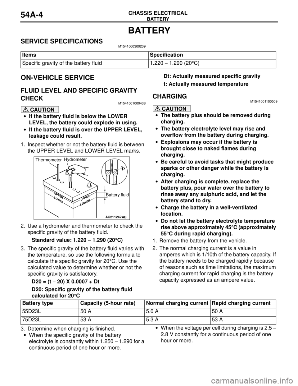
1. Inspect whether or not the battery fluid is between
the UPPER LEVEL and LOWER LEVEL marks.
2. Use a hydrometer and thermometer to check the
specific gravity of the battery fluid.
Standard value: 1.220 − 1.290 (20°C)
3. The specific gravity of the battery fluid varies with
the temperature, so use the following formula to
calculate the specific gravity for 20°C. Use the
calculated value to determine whether or not the
specific gravity is satisfactory.
D20 = (t − 20) X 0.0007 + Dt
D20: Specific gravity of the battery fluid
calculated for 20°CDt: Actually measured specific gravity
t: Actually measured temperature
CHARGINGM1541001100509
CAUTION
•The battery plus should be removed during
charging.
•The battery electrolyte level may rise and
overflow from the battery during charging.
•Explosions may occur if the battery is
brought close to naked flames during
charging.
•Be careful to avoid tasks that might produce
sparks or other danger while the battery is
charging.
•After charging is complete, replace the
battery plus, pour water over the battery to
rinse away any sulphuric acid, and let the
battery stand to dry.
•Charge the battery in a well-ventilated
location.
•Do not let the battery electrolyte temperature
rise above approximately 45°C (approximately
55°C during rapid charging).
1. Remove the battery from the vehicle.
2. The normal charging current is a value in
amperes which is 1/10th of the battery capacity. If
the battery needs to be charged rapidly because
of reasons such as time limitations, the maximum
charging current for rapid charging is the battery
capacity expressed as an ampere value.
3. Determine when charging is finished.
•When the specific gravity of the battery
electrolyte is constantly within 1.250 − 1.290 for a
continuous period of one hour or more.•When the voltage per cell during charging is 2.5 −
2.8 V constantly for a continuous period of one
hour or more. Items Specification
Specific gravity of the battery fluid 1.220 − 1.290 (20°C)
AC211242AB
Battery fluid ThermometerHydrometer
Battery type Capacity (5-hour rate) Normal charging current Rapid charging current
55D23L 50 A 5.0 A 50 A
75D23L 53 A 5.3 A 53 A