oil type MITSUBISHI LANCER 2005 Workshop Manual
[x] Cancel search | Manufacturer: MITSUBISHI, Model Year: 2005, Model line: LANCER, Model: MITSUBISHI LANCER 2005Pages: 788, PDF Size: 45.98 MB
Page 8 of 788

GENERAL INFORMATION
ENGINE LUBRICATION12-2
GENERAL INFORMATION
M1121000100357
The lubrication method is a fully force-fed, full-flow
filtration type. The engine oil pump is a trochoid type
which is driven by the crankshaft <4G1>.The engine
oil pump is a gear type which is driven by the
crankshaft via the balancer timing belt <4G6>.
ENGINE OILS
Health Warning
Prolonged and repeated contact with mineral oil will
result in the removal of natural fats from the skin,
leading to dryness, irritation and dermatitis. In
addition, used engine oil contains potentially harmful
contaminants which may cause skin cancer.
Adequate means of skin protection and washing
facilities must be provided.
Recommended Precautions
The most effective precaution is to adapt working
practices which prevent, as far as practicable, the
risk of skin contact with mineral oils, for example by
using enclosed systems for handling used engine oil
and by degreasing components, where practicable,
before handling them. Other precautions:
•Avoid prolonged and repeated contact with oils,
particularly used engine oils.
•Wear protective clothing, including impervious
gloves where practicable.•Avoid contaminating clothes, particularly
underpants, with oil.
•Do not put oily rags in pockets, the use of overalls
without pockets will avoid this.
•Do not wear heavily soiled clothing and
oil-impregnated foot-wear. Overalls must be
cleaned regularly and kept separate from
personal clothing.
•Where there is a risk of eye contact, eye
protection should be worn, for example, chemical
goggles or face shields; in addition an eye wash
facility should be provided.
•Obtain first aid treatment immediately for open
cuts and wounds.
•Wash regularly with soap and water to ensure all
oil is removed, especially before meals (skin
cleansers and nail brushes will help). After
cleaning, the application of preparations
containing lanolin to replace the natural skin oils
is advised.
•Do not use petrol, kerosine, diesel fuel, gas oil,
thinners or solvents for cleaning skin.
•Use barrier creams, applying them before each
work period, to help the removal of oil from the
skin after work.
•If skin disorders develop, obtain medical advice
without delay.
SERVICE SPECIFICATION
M1121000300232
LUBRICANT
M1121000400433
Item Standard value
Oil pressure kPa at idle 29 or more
at 3,500 r/min 294 − 686
Item Specification
Engine oil ACEA classification A1, A2 or A3
Engine oil API classification SG or higher
Engine oil quantity L 4G1 Oil filter 0.3
To t a l 3 . 3
4G6 Oil filter 0.3
To t a l 4 . 3
Page 16 of 788

GENERAL INFORMATION
ENGINE COOLING14-2
GENERAL INFORMATION
M1141000100371The cooling system is designed to keep every part of
the engine at appropriate temperature in whatever
condition the engine may be operated. The cooling
method is of the water-cooled, pressure forced
circulation type in which the water pump pressurizes
coolant and circulates it throughout the engine. If the
coolant temperature exceeds the prescribed temperature, the thermostat opens to circulate the
coolant through the radiator as well so that the heat
absorbed by the coolant may be radiated into the air.
The water pump is of the centrifugal type and is
driven by the alternator drive belt from the
crankshaft. The radiator is the corrugated fin, down
flow type.
SERVICE SPECIFICATIONS
M1141000300416
LUBRICANT
M1141000400338
ItemSpecification
Radiator Performance kJ/h 4G13 Standard vehicles 137,720
Vehicles with capacity up radiator
(option)161,288
4G18 Standard vehicles 161,288
Vehicles with capacity up radiator
(option)181,800
4G63 181,800
A/T oil cooler Performance kJ/h 5,651
Item Standard value Limit
High-pressure valve opening pressure of radiator cap kPa 93 − 123 Minimum 83
Range of coolant antifreeze concentration of radiator % 30 − 60 -
Thermostat Valve opening temperature of
thermostat °C4G1 88 ± 1.5 -
4G6 82 ± 1.5 -
Full-opening temperature of
thermostat °C4G1 100 -
4G6 95 -
Valve lift mm 8.5 or more -
Item Specified coolant Quantity L
Engine coolant (including
condense tank)DIAQUEEN SUPER LONG LIFE COOLANT
or an equivalent4G1 5.0
4G6 7.0
Page 66 of 788
CHARGING SYSTEM
ENGINE ELECTRICAL16-2
CHARGING SYSTEM
GENERAL INFORMATIONM1161000100522
The charging system uses the alternator output to
keep the battery charged at a constant level under
various electrical loads.
OPERATION
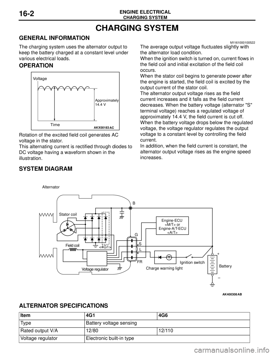
Rotation of the excited field coil generates AC
voltage in the stator.
This alternating current is rectified through diodes to
DC voltage having a waveform shown in the
illustration.The average output voltage fluctuates slightly with
the alternator load condition.
When the ignition switch is turned on, current flows in
the field coil and initial excitation of the field coil
occurs.
When the stator coil begins to generate power after
the engine is started, the field coil is excited by the
output current of the stator coil.
The alternator output voltage rises as the field
current increases and it falls as the field current
decreases. When the battery voltage (alternator "S"
terminal voltage) reaches a regulated voltage of
approximately 14.4 V, the field current is cut off.
When the battery voltage drops below the regulated
voltage, the voltage regulator regulates the output
voltage to a constant level by controlling the field
current.
In addition, when the field current is constant, the
alternator output voltage rises as the engine speed
increases.
SYSTEM DIAGRAM
ALTERNATOR SPECIFICATIONS
AKX00183
Voltage
Time
Approximately
14.4 V
AC
AK400308
Alternator
B
Stator coil
Engine-ECU
Engine-A/T-ECU
G
S
L
FR <4G1>
Voltage regulatorCharge warning lightIgnition switch
Battery Field coil
+
–
AB
Item 4G1 4G6
Type Battery voltage sensing
Rated output V/A 12/80 12/110
Voltage regulator Electronic built-in type
Page 95 of 788
IGNITION SYSTEM
ENGINE ELECTRICAL16-31
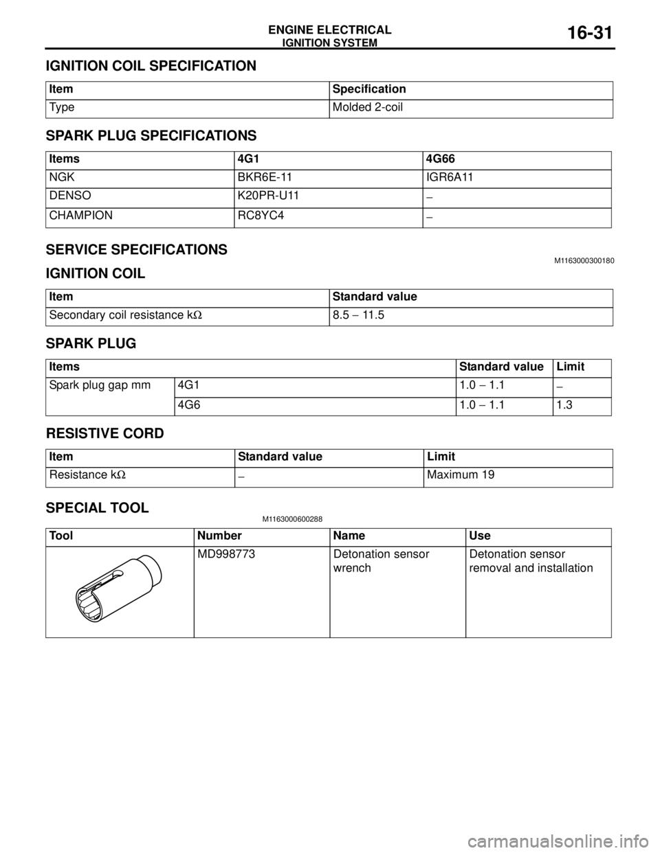
IGNITION COIL SPECIFICATION
SPARK PLUG SPECIFICATIONS
SERVICE SPECIFICATIONS
M1163000300180
IGNITION COIL
SPARK PLUG
RESISTIVE CORD
SPECIAL TOOL
M1163000600288
Item Specification
Type Molded 2-coil
Items 4G1 4G66
NGK BKR6E-11 IGR6A11
DENSO K20PR-U11
−
CHAMPION RC8YC4
−
Item Standard value
Secondary coil resistance kΩ8.5 − 11 . 5
ItemsStandard value Limit
Spark plug gap mm 4G1 1.0 − 1.1
−
4G6 1.0 − 1.1 1.3
Item Standard value Limit
Resistance kΩ
−Maximum 19
Tool Number Name Use
MD998773 Detonation sensor
wrenchDetonation sensor
removal and installation
Page 96 of 788
IGNITION SYSTEM
ENGINE ELECTRICAL16-32
ON-VEHICLE SERVICE
IGNITION COIL (WITH BUILT-IN POWER
TRANSISTOR) CHECK
M1163001200324
Check by the following procedure, and replace if
there is a malfunction.
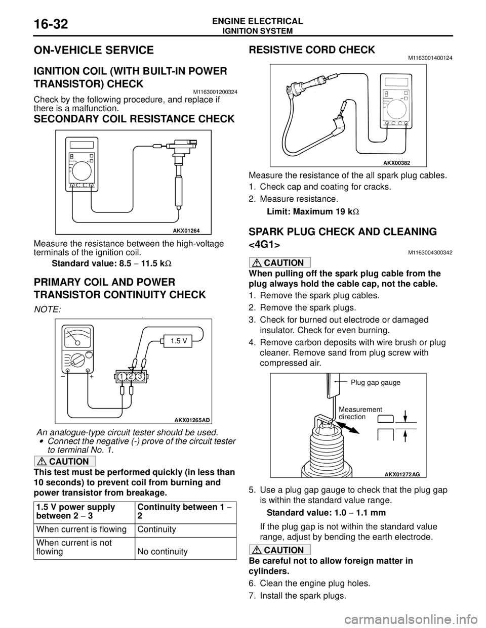
SECONDARY COIL RESISTANCE CHECK
Measure the resistance between the high-voltage
terminals of the ignition coil.
Standard value: 8.5 − 11.5 kΩ
PRIMARY COIL AND POWER
TRANSISTOR CONTINUITY CHECK
NOTE: .•
An analogue-type circuit tester should be used.
•Connect the negative (-) prove of the circuit tester
to terminal No. 1.
CAUTION
This test must be performed quickly (in less than
10 seconds) to prevent coil from burning and
power transistor from breakage.
RESISTIVE CORD CHECKM1163001400124
Measure the resistance of the all spark plug cables.
1. Check cap and coating for cracks.
2. Measure resistance.
Limit: Maximum 19 kΩ
SPARK PLUG CHECK AND CLEANING
<4G1>
M1163004300342
CAUTION
When pulling off the spark plug cable from the
plug always hold the cable cap, not the cable.
1. Remove the spark plug cables.
2. Remove the spark plugs.
3. Check for burned out electrode or damaged
insulator. Check for even burning.
4. Remove carbon deposits with wire brush or plug
cleaner. Remove sand from plug screw with
compressed air.
5. Use a plug gap gauge to check that the plug gap
is within the standard value range.
Standard value: 1.0 − 1.1 mm
If the plug gap is not within the standard value
range, adjust by bending the earth electrode.
CAUTION
Be careful not to allow foreign matter in
cylinders.
6. Clean the engine plug holes.
7. Install the spark plugs. 1.5 V power supply
between 2 − 3Continuity between 1 −
2
When current is flowing Continuity
When current is not
flowing No continuity
AKX01264
AKX01265AD
1.5 V
123 +
–
AKX00382
AKX01272
AG
Plug gap gauge
Measurement
direction
Page 113 of 788

EMISSION CONTROL
ENGINE AND EMISSION CONTROL17-5
EMISSION CONTROL
GENERAL INFORMATIONM1173000100370
The emission control system consists of the following
subsystems:•Crankcase emission control system
•Evaporative emission control system
•Exhaust emission control system
EMISSION CONTROL DEVICE
REFERENCE TABLE
M1173006600135
SERVICE SPECIFICATION(S)M1173000300288
Items Name Specification
Crankcase emission control
systemPositive crankcase ventilation
(PCV) valveVariable flow type
(Purpose: HC reduction)
Evaporative emission control
systemCanister
Purge control solenoid valveEquipped
Duty cycle type solenoid valve
(Purpose: HC reduction)
Exhaust emission control system Air-fuel ratio control device - MPI
systemOxygen sensor feedback type
(Purpose: CO, HC, NOx reduction)
Exhaust gas recirculation system
•EGR valve
•EGR control solenoid valveEquipped
Single type
Duty cycle type solenoid valve
(Purpose: NOx reduction)
Catalytic converter Monolith type
(Purpose: CO, HC, NOx reduction)
Related parts Crankcase
emission
control
systemEvaporative
emission
control
systemAir/fuel ratio
control
systemCatalytic
converterExhaust gas
recirculation
system
PCV valve
×
Purge control solenoid valve
×
MPI system component
××
Catalytic converter
×
EGR valve
×
EGR control solenoid valve
×
Items Standard value
Purge control solenoid valve coil resistance (at 20°C) Ω30 − 34
EGR control solenoid valve coil resistance (at 20°C) Ω29 − 35
Page 134 of 788
GENERAL INFORMATION
FRONT AXLE26-2
GENERAL INFORMATION
M1261000100347
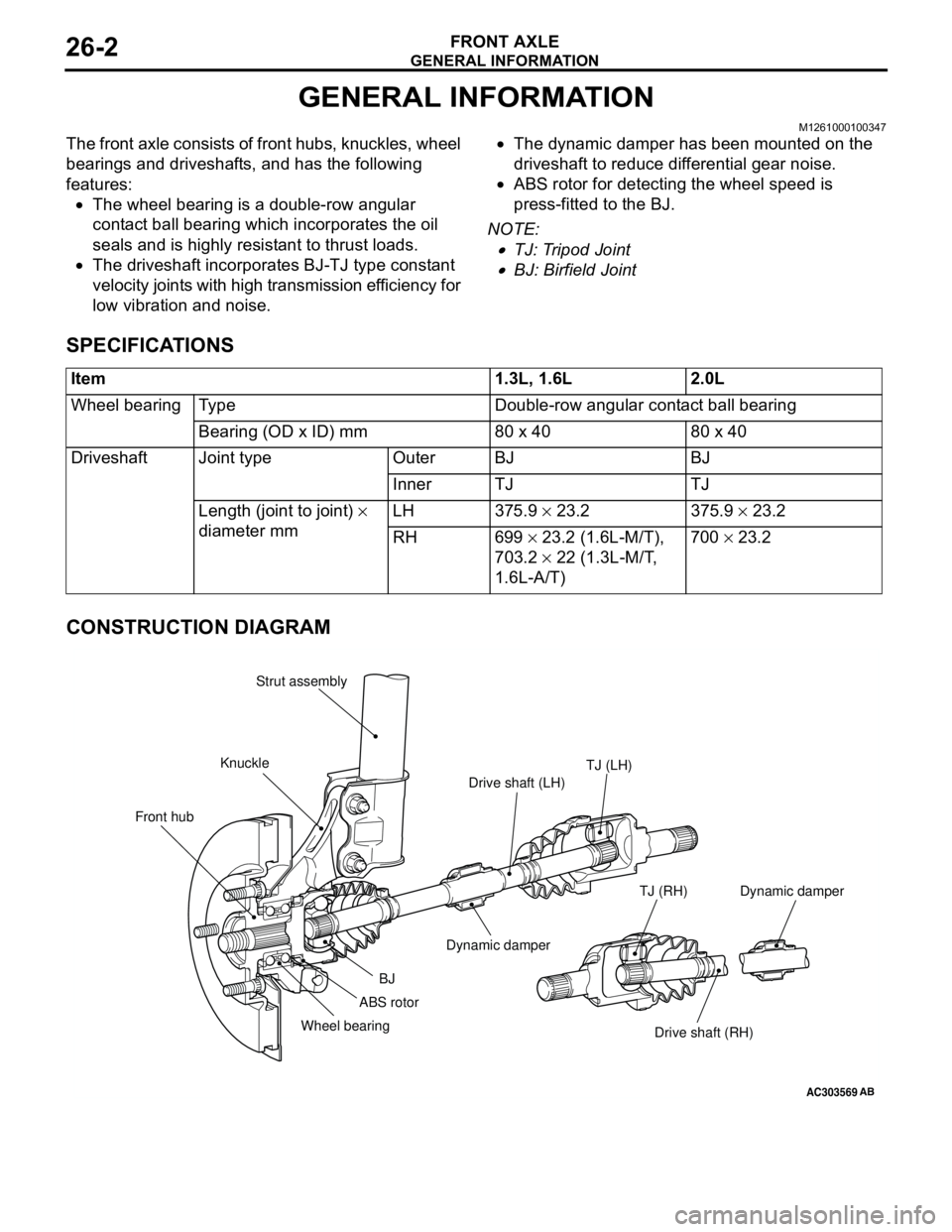
The front axle consists of front hubs, knuckles, wheel
bearings and driveshafts, and has the following
features:
•The wheel bearing is a double-row angular
contact ball bearing which incorporates the oil
seals and is highly resistant to thrust loads.
•The driveshaft incorporates BJ-TJ type constant
velocity joints with high transmission efficiency for
low vibration and noise.•The dynamic damper has been mounted on the
driveshaft to reduce differential gear noise.
•ABS rotor for detecting the wheel speed is
press-fitted to the BJ.
NOTE: .
•TJ: Tripod Joint
•BJ: Birfield Joint
SPECIFICATIONS
CONSTRUCTION DIAGRAM
Item 1.3L, 1.6L 2.0L
Wheel bearing Type Double-row angular contact ball bearing
Bearing (OD x ID) mm 80 x 40 80 x 40
Driveshaft Joint type Outer BJ BJ
Inner TJ TJ
Length (joint to joint) ×
diameter mm LH 375.9 × 23.2 375.9 × 23.2
RH 699 × 23.2 (1.6L-M/T),
703.2 × 22 (1.3L-M/T,
1.6L-A/T)700 × 23.2
AC303569
Front hubKnuckleStrut assembly
TJ (LH)
Drive shaft (LH)
Dynamic damper
BJ
Wheel bearing
Drive shaft (RH) TJ (RH)
AB
ABS rotorDynamic damper
Page 184 of 788
GENERAL INFORMATION
FRONT SUSPENSION33-2
GENERAL INFORMATION
M1332000100407
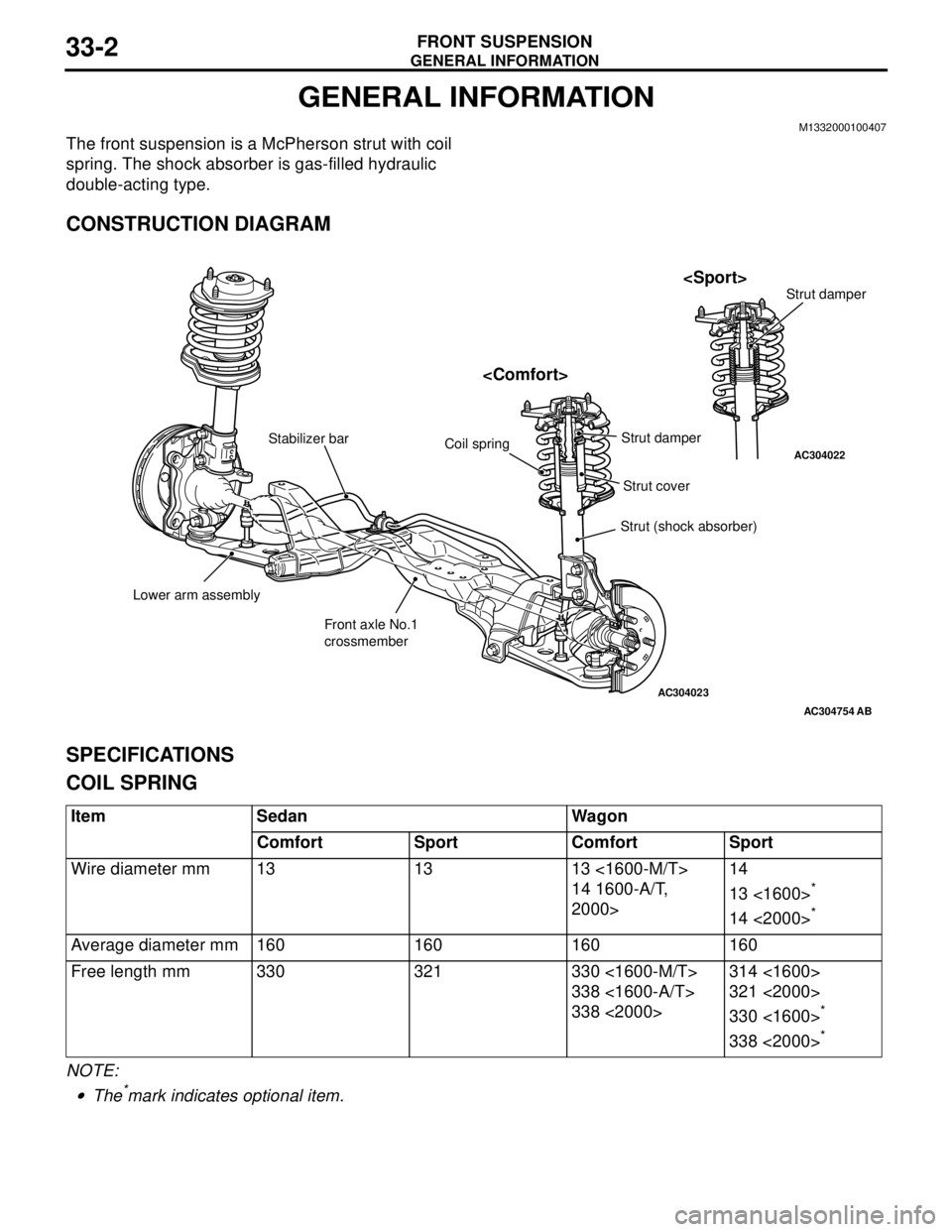
The front suspension is a McPherson strut with coil
spring. The shock absorber is gas-filled hydraulic
double-acting type.
CONSTRUCTION DIAGRAM
SPECIFICATIONS
COIL SPRING
NOTE: .
•The*mark indicates optional item.
AC304023
AC304022
AC304754
Lower arm assembly
Front axle No.1
crossmember Stabilizer bar
Strut (shock absorber) Coil spring
AB
Strut cover Strut damper
Item Sedan Wagon
Comfort Sport Comfort Sport
Wire diameter mm 13 13 13 <1600-M/T>
14 1600-A/T,
2000>14
13 <1600>
*
14 <2000>*
Average diameter mm 160 160 160 160
Free length mm 330 321 330 <1600-M/T>
338 <1600-A/T>
338 <2000>314 <1600>
321 <2000>
330 <1600>
*
338 <2000>*
Page 202 of 788
GENERAL INFORMATION
REAR SUSPENSION34-2
GENERAL INFORMATION
M1341000100353
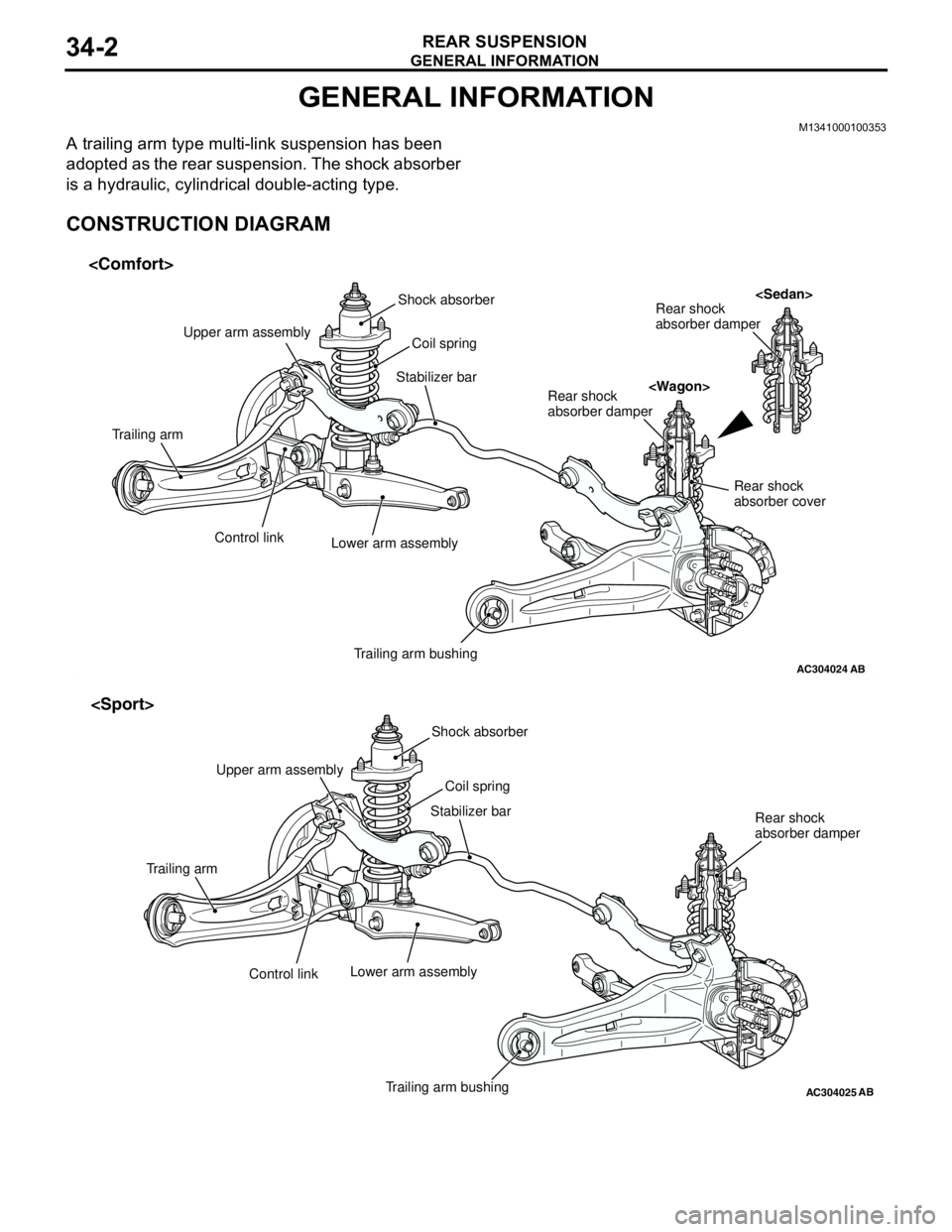
A trailing arm type multi-link suspension has been
adopted as the rear suspension. The shock absorber
is a hydraulic, cylindrical double-acting type.
CONSTRUCTION DIAGRAM
AC304024AB
Shock absorber
Coil spring
Trailing arm bushing Lower arm assembly Control link Trailing armUpper arm assembly
Stabilizer barRear shock
absorber damper
Rear shock
absorber damper
Rear shock
absorber cover
AC304025AB
Shock absorber
Trailing arm bushing Control link Trailing armStabilizer bar
Coil spring
Lower arm assembly
Rear shock
absorber damper Upper arm assembly
Page 237 of 788

GENERAL INFORMATION
POWER STEERING37-3
GENERAL INFORMATION
M1372000100337
Power steering has been adopted in all vehicles to
make the steering system easier to handle.
FEATURES
•A 4-spoke steering wheel is used.
•MOMO leather-wrapped 3-spoke steering wheel
is used.
•A steering column has a shock absorbing
mechanism and a tilt steering mechanism.•Integral-type rack and pinion gear with high
rigidity and excellent response is used.
•A vane type pump with a fluid flow rate control
system which change steering effort according to
the engine speed is used.
•The separate plastic resin oil reservoir is used to
reduce weight and to make the fluid level
checking easier.
SPECIFICATIONS
Item Comfort Sport
Steering
wheelType 4-spoke type MOMO leather-wrapped
3-spoke type
Outside diameter mm 380 365
Maximum number of turns 3.19 2.86
3.08
Steering
columnColumn mechanism Shock absorbing mechanism and Tilt steering mechanism
Power steering type Integral type
Oil pump Type Vane pump
Basic discharge amount cm
3/rev.7.2 <1300, 1600>
8.1 <2000>7.2 <1300, 1600>
8.1 <2000>
Relief pressure MPa 8.8 8.8
Reservoir type Separate type (plastic)
Pressure switch Equipped
Steering
gearType Rack and pinion
Stroke ratio (Rack stroke/Steering
wheel maximum turning radius)45.74 45.74
Rack stroke mm 146 131
141