key MITSUBISHI LANCER 2005 User Guide
[x] Cancel search | Manufacturer: MITSUBISHI, Model Year: 2005, Model line: LANCER, Model: MITSUBISHI LANCER 2005Pages: 788, PDF Size: 45.98 MB
Page 332 of 788
KEYLESS ENTRY SYSTEM
BODY42-54
•Enable the hazard answerback function
when the doors are locked: The
ETACS-ECU buzzer will sound once.
•Disable the hazard answerback function
when the doors are locked: The
ETACS-ECU buzzer will sound twice.
3. If the transmitter “UNLOCK” button is pushed
consecutively twice (within two seconds), the
ETACS-ECU buzzer will sound, indicating that the
hazard answerback function can be enabled or
disabled when the doors are unlocked.
•Enable the hazard answerback function
when the doors are unlocked: The
ETACS-ECU buzzer will sound once.
•Disable the hazard answerback function
when the doors are unlocked: The
ETACS-ECU buzzer will sound twice.
4. Exit the hazard answerback customize mode by
observing one of the following steps.
(1) Disconnect diagnosis connector terminal (1)
form the earth.
(2) Turn the ignition switch to position other then
“LOCK”(OFF), or remove the ignition key.
(3) Open the driver's side door.
(4) Any other warning buzzer output occurs.
NOTE: If any operation is not done for at least three
minutes after the ETACS-ECU has entered the
customize mode, the hazard answerback customize
mode will be canceled automatically.
connector>
1. Enter the hazard answerback customize mode by
performing one of the following steps. If the
ETACS-ECU enters the customize mode, its
buzzer will sound once.
(1) Turn the ignition switch to “LOCK”(OFF)
position.
(2) Turn off the hazard warning lamp switch.
CAUTION
Before connecting or disconnecting the MUT-II,
turn the ignition switch to the "LOCK" (OFF)
position.
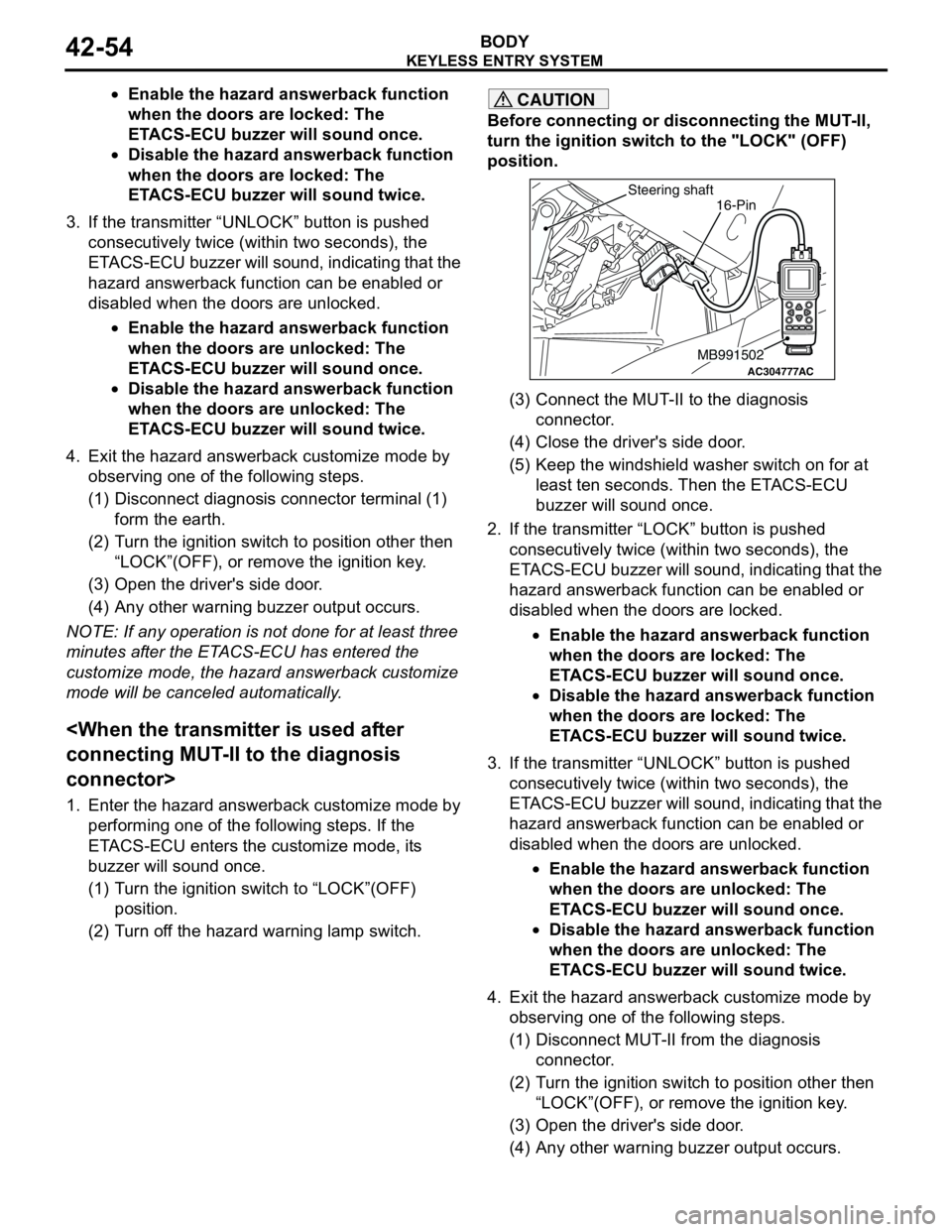
(3) Connect the MUT-II to the diagnosis
connector.
(4) Close the driver's side door.
(5) Keep the windshield washer switch on for at
least ten seconds. Then the ETACS-ECU
buzzer will sound once.
2. If the transmitter “LOCK” button is pushed
consecutively twice (within two seconds), the
ETACS-ECU buzzer will sound, indicating that the
hazard answerback function can be enabled or
disabled when the doors are locked.
•Enable the hazard answerback function
when the doors are locked: The
ETACS-ECU buzzer will sound once.
•Disable the hazard answerback function
when the doors are locked: The
ETACS-ECU buzzer will sound twice.
3. If the transmitter “UNLOCK” button is pushed
consecutively twice (within two seconds), the
ETACS-ECU buzzer will sound, indicating that the
hazard answerback function can be enabled or
disabled when the doors are unlocked.
•Enable the hazard answerback function
when the doors are unlocked: The
ETACS-ECU buzzer will sound once.
•Disable the hazard answerback function
when the doors are unlocked: The
ETACS-ECU buzzer will sound twice.
4. Exit the hazard answerback customize mode by
observing one of the following steps.
(1) Disconnect MUT-II from the diagnosis
connector.
(2) Turn the ignition switch to position other then
“LOCK”(OFF), or remove the ignition key.
(3) Open the driver's side door.
(4) Any other warning buzzer output occurs.
AC304777
Steering shaft
ACMB991502
16-Pin
Page 333 of 788
KEYLESS ENTRY SYSTEM
BODY42-55
NOTE: If any operation is not done for at least three
minutes after the ETACS-ECU has entered the
customize mode, the hazard answerback customize
mode will be canceled automatically.
(MB991824) to the diagnosis connector>
1. Enter the hazard answerback customize mode by
performing one of the following steps. If the
ETACS-ECU enters the customize mode, its
buzzer will sound once.
(1) Turn the ignition switch to “LOCK”(OFF)
position.
(2) Turn off the hazard warning lamp switch.
CAUTION
Before connecting or disconnecting the V. C. I.,
turn the ignition switch to the "LOCK" (OFF)
position.
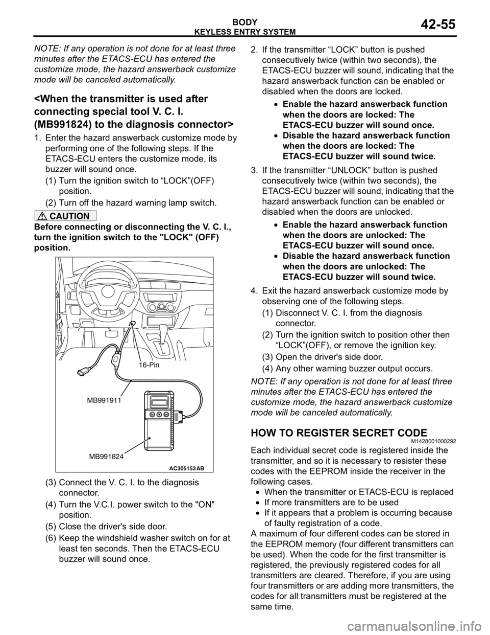
(3) Connect the V. C. I. to the diagnosis
connector.
(4) Turn the V.C.I. power switch to the "ON"
position.
(5) Close the driver's side door.
(6) Keep the windshield washer switch on for at
least ten seconds. Then the ETACS-ECU
buzzer will sound once.2. If the transmitter “LOCK” button is pushed
consecutively twice (within two seconds), the
ETACS-ECU buzzer will sound, indicating that the
hazard answerback function can be enabled or
disabled when the doors are locked.
•Enable the hazard answerback function
when the doors are locked: The
ETACS-ECU buzzer will sound once.
•Disable the hazard answerback function
when the doors are locked: The
ETACS-ECU buzzer will sound twice.
3. If the transmitter “UNLOCK” button is pushed
consecutively twice (within two seconds), the
ETACS-ECU buzzer will sound, indicating that the
hazard answerback function can be enabled or
disabled when the doors are unlocked.
•Enable the hazard answerback function
when the doors are unlocked: The
ETACS-ECU buzzer will sound once.
•Disable the hazard answerback function
when the doors are unlocked: The
ETACS-ECU buzzer will sound twice.
4. Exit the hazard answerback customize mode by
observing one of the following steps.
(1) Disconnect V. C. I. from the diagnosis
connector.
(2) Turn the ignition switch to position other then
“LOCK”(OFF), or remove the ignition key.
(3) Open the driver's side door.
(4) Any other warning buzzer output occurs.
NOTE: If any operation is not done for at least three
minutes after the ETACS-ECU has entered the
customize mode, the hazard answerback customize
mode will be canceled automatically.
HOW TO REGISTER SECRET CODEM1428001000292
Each individual secret code is registered inside the
transmitter, and so it is necessary to resister these
codes with the EEPROM inside the receiver in the
following cases.
•When the transmitter or ETACS-ECU is replaced
•If more transmitters are to be used
•If it appears that a problem is occurring because
of faulty registration of a code.
A maximum of four different codes can be stored in
the EEPROM memory (four different transmitters can
be used). When the code for the first transmitter is
registered, the previously registered codes for all
transmitters are cleared. Therefore, if you are using
four transmitters or are adding more transmitters, the
codes for all transmitters must be registered at the
same time.
AC305153AB
MB991911
MB991824
16-Pin
Page 334 of 788

KEYLESS ENTRY SYSTEM
BODY42-56
WHEN THE SPECIAL TOOL DIAGNOSIS
CODE CHECK HARNESS (MB991529) IS
USED
1. Check that the doors lock normally when the key
is used.
2. Insert the ignition key.
CAUTION
Before connecting or disconnecting the earth,
turn the ignition switch to the "LOCK" (OFF)
position.
3. Connect the diagnosis connector to the special
tool diagnosis code check harness (MB991529).
NOTE: This will connect terminal (1) of the
diagnosis connector to earth, and the system will
be in secret code registration standby mode.
4. Press the hazard warning lamp switch six times
within 10 seconds.
NOTE: Once the process is completed six times,
then it will operate with all doors and tailgate lock
and unlock operations once and then go to the
save mode.
NOTE: The hazard warning lamp switch is turned
on and off alternately whenever it is pushed.
5. Press the transmitter switch, and then press it two
times within 10 seconds of the first press. This will
register the code.
6. Once the program is saved, it will operate once
with the all doors and tailgate lock and unlock
operations. 7. If you are using two or more transmitters or have
added a second transmitter, the same registration
procedure should be carried out within one minute
after registering the code for the first transmitter.
8. Registration mode will be cancelled under the
following conditions:
•When the secret code for four transmitters has
been registered;
•When one minute has passed after registration
mode started;
•When the diagnosis connector is disconnected
from earth;
•When the key is removed from the key cylinder;
9. After the registration is completed, remove the
ignition key and close all the doors, and then
check that the keyless entry system operates
normally.
WHEN THE MUT-II IS USED
1. Check that the doors lock normally when the key
is used.
2. Insert the ignition key.
CAUTION
Before connecting or disconnecting the MUT-II,
turn the ignition switch to the "LOCK" (OFF)
position.
3. Connect the MUT-II to the diagnosis connector.
4. Press the hazard warning switch six times within
10 seconds.
AC305133AB
Diagnosis
connector
MB991529Steering shaft
ACX00571
Ground connected
Within 10 seconds
Hazard
warning
switchON
OFF12345
6
AGAC304777
Steering shaft
ACMB991502
16-Pin
ACX00571
MUT-II connected
Within 10 seconds
Hazard
warning
switchON
OFF12345
6
AB
Page 335 of 788
KEYLESS ENTRY SYSTEM
BODY42-57
NOTE: Once the process is completed six times,
then it will operate with all doors and tailgate lock
and unlock operations once and then go to the
save mode.
NOTE: The hazard warning lamp switch is turned
on and off alternately whenever it is pushed.
5. Press the transmitter switch, and then press it two
times within 10 seconds of the first press. This will
register the code.
6. Once the program is saved, it will operate once
with the all doors and tailgate lock and unlock
operations.
7. If you are using two or more transmitters or have
added a second transmitter, the same registration
procedure should be carried out within one minute
after registering the code for the first transmitter.
8. Registration mode will be cancelled under the
following conditions:
•When the secret code for four transmitters has
been registered;
•When one minute has passed after registration
mode started;
•When the MUT-II is disconnected from the
diagnosis connector;
•When the key is removed from the key cylinder;
9. After the registration is completed, remove the
ignition key and close all the doors, and then
check that the keyless entry system operates
normally.
WHEN THE SPECIAL TOOL V. C. I.
(MB991824) IS USED
1. Check that the doors lock normally when the key
is used.
2. Insert the ignition key.
CAUTION
Before connecting or disconnecting the V. C. I.,
turn the ignition switch to the "LOCK" (OFF)
position.
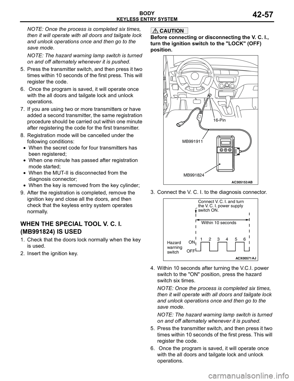
3. Connect the V. C. I. to the diagnosis connector.
4. Within 10 seconds after turning the V.C.I. power
switch to the "ON" position, press the hazard
switch six times.
NOTE: Once the process is completed six times,
then it will operate with all doors and tailgate lock
and unlock operations once and then go to the
save mode.
NOTE: The hazard warning lamp switch is turned
on and off alternately whenever it is pushed.
5. Press the transmitter switch, and then press it two
times within 10 seconds of the first press. This will
register the code.
6. Once the program is saved, it will operate once
with the all doors and tailgate lock and unlock
operations.
AC305153AB
MB991911
MB991824
16-Pin
ACX00571
Connect V. C. I. and turn
the V. C. I. power supply
switch ON.
Within 10 seconds
Hazard
warning
switchON
OFF1234 56
AJ
Page 336 of 788
KEYLESS ENTRY SYSTEM
BODY42-58
7. If you are using two or more transmitters or have
added a second transmitter, the same registration
procedure should be carried out within one minute
after registering the code for the first transmitter.
8. Registration mode will be cancelled under the
following conditions:
•When the secret code for four transmitters has
been registered;•When one minute has passed after registration
mode started;
•When the V.C.I. is disconnected from the
diagnosis connector;
•When the key is removed from the key cylinder;
9. After the registration is completed, remove the
ignition key and close all the doors, and then
check that the keyless entry system operates
normally.
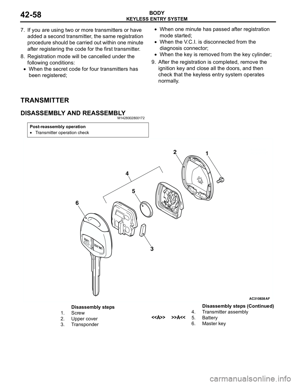
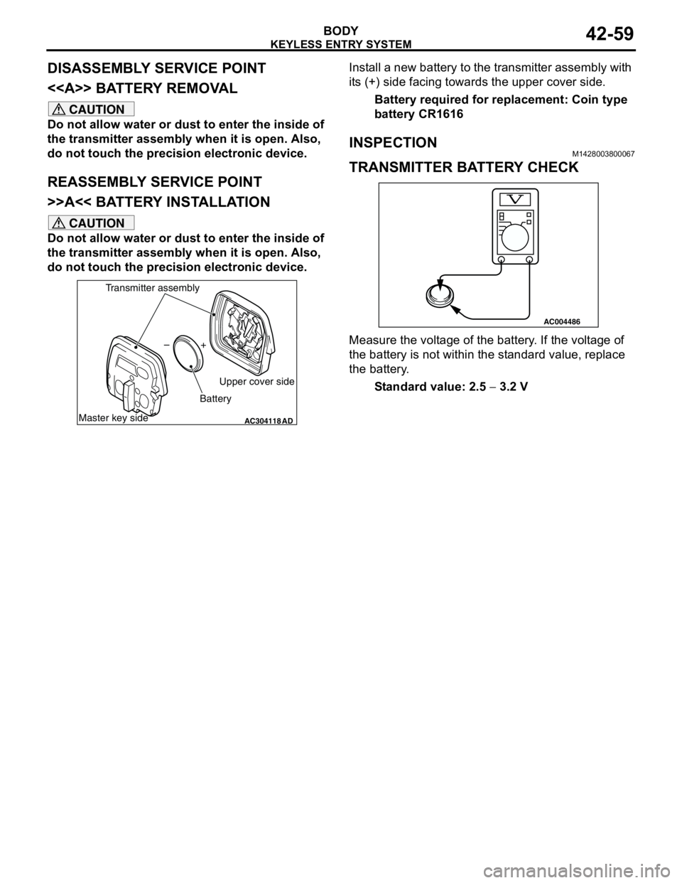
TRANSMITTER
DISASSEMBLY AND REASSEMBLYM1428002800172
Post-reassembly operation
•Transmitter operation check
AC310838AC303199
AC3041181 2
AF
5
3
4
6
Disassembly steps
1. Screw
2. Upper cover
3. Transponder4. Transmitter assembly
<> >>A<<5. Battery
6. Master keyDisassembly steps (Continued)
Page 337 of 788
Page 389 of 788
54A-1
GROUP 54A
CHASSIS
ELECTRICAL
CONTENTS
BATTERY. . . . . . . . . . . . . . . . . .
54A-4
SERVICE SPECIFICATIONS. . . . .
54A-4
ON-VEHICLE SERVICE. . . . . . . . .54A-4
FLUID LEVEL AND SPECIFIC
GRAVITY CHECK . . . . . . . . . . . . . . . . . 54A-4
CHARGING . . . . . . . . . . . . . . . . . . . . . . 54A-4
BATTERY TEST . . . . . . . . . . . . . . . . . . 54A-5
IGNITION SWITCH* . . . . . . . . . .54A-6
GENERAL INFORMATION . . . . . .
54A-6
SPECIAL TOOLS. . . . . . . . . . . . . .54A-8
TROUBLESHOOTING . . . . . . . . . .54A-9
IGNITION KEY REMINDER BUZZER AND
DOOR LOCK PREVENTION FUNCTION
TROUBLESHOOTING . . . . . . . . . . . . . . 54A-9
IMMOBILIZER SYSTEM
TROUBLESHOOTING . . . . . . . . . .
54A-9
DIAGNOSIS CODE CHART . . . . . . . . . . 54A-9
DIAGNOSTIC TROUBLE CODE
PROCEDURES . . . . . . . . . . . . . . . .
54A-10
SYMPTOM CHART. . . . . . . . . . . . .54A-11
SYMPTOM PROCEDURES . . . . . .54A-12
DATA LIST REFERENCE TABLE .54A-19
CHECK IMMOBILIZER-ECU . . . . .54A-19
ON-VEHICLE SERVICE . . . . . . . . .54A-20
HOW TO REGISTER ENCRYPTED
CODE . . . . . . . . . . . . . . . . . . . . . . . . . . . 54A-20
IGNITION SWITCH . . . . . . . . . . . . . . . . 54A-27
REMOVAL AND INSTALLATION . . . . . . 54A-27
INSPECTION . . . . . . . . . . . . . . . . . . . . . 54A-28
Continued on next page
WARNINGS REGARDING SERVICING OF SUPPLEMENTAL RESTRAINT SYSTEM (SRS) EQUIPPED VEHICLES
WARNING
•Improper service or maintenance of any component of the SRS, or any SRS-related component, can lead to
personal injury or death to service personnel (from inadvertent firing of the air bag) or to the driver and
paassenger (from rendering the SRS inoperative).
•Service or maintenance of any SRS component or SRS-related component must be performed only at an
authorized MITSUBISHI dealer.
•MITSUBISHI dealer personnel must thoroughly review this manual, and especially its GROUP 52B - Supplemental
Restraint System (SRS) before beginning any service or maintenance of any component of the SRS or any
SRS-related component.
NOTE
The SRS includes the following components: SRS air bag control unit, SRS warning light, front impact sensors, air bag module,
clock spring, and interconnecting wiring. Other SRS-related components (that may have to be removed/installed in connection
with SRS service or maintenance) are indicated in the table of contents by an asterisk (*).
Page 394 of 788
IGNITION SWITCH
CHASSIS ELECTRICAL54A-6
IGNITION SWITCH
GENERAL INFORMATIONM1543009901274
IGNITION KEY REMINDER BUZZER
The ignition key reminder buzzer will sound under
the following condition, and warn the driver to
remove the ignition key.
•The driver's door is opened when the ignition
switch is at "LOCK" (OFF) or "ACC" position
without removing the ignition key.
However, the lamp reminder buzzer will take
precedence over this function.
DOOR LOCK PREVENTION FUNCTION
If the key is left in the ignition switch while the driver’s
door opened or the assistant door opened, all door
are automatically unlock to prevent locking the
ignition key in the vehicle after door is locked.
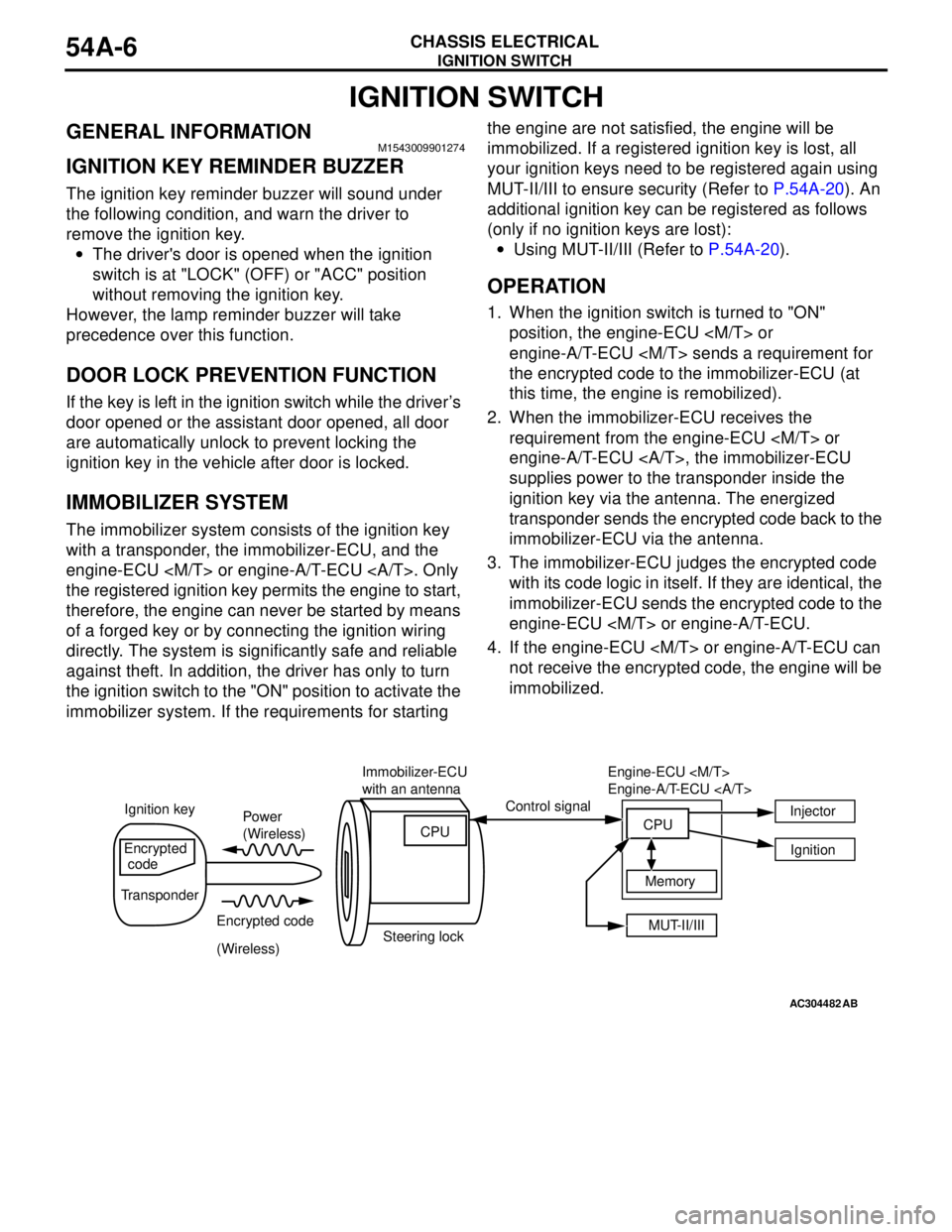
IMMOBILIZER SYSTEM
The immobilizer system consists of the ignition key
with a transponder, the immobilizer-ECU, and the
engine-ECU
the registered ignition key permits the engine to start,
therefore, the engine can never be started by means
of a forged key or by connecting the ignition wiring
directly. The system is significantly safe and reliable
against theft. In addition, the driver has only to turn
the ignition switch to the "ON" position to activate the
immobilizer system. If the requirements for starting the engine are not satisfied, the engine will be
immobilized. If a registered ignition key is lost, all
your ignition keys need to be registered again using
MUT-II/III to ensure security (Refer to P.54A-20). An
additional ignition key can be registered as follows
(only if no ignition keys are lost):
•Using MUT-II/III (Refer to P.54A-20).
OPERATION
1. When the ignition switch is turned to "ON"
position, the engine-ECU
engine-A/T-ECU
the encrypted code to the immobilizer-ECU (at
this time, the engine is remobilized).
2. When the immobilizer-ECU receives the
requirement from the engine-ECU
engine-A/T-ECU , the immobilizer-ECU
supplies power to the transponder inside the
ignition key via the antenna. The energized
transponder sends the encrypted code back to the
immobilizer-ECU via the antenna.
3. The immobilizer-ECU judges the encrypted code
with its code logic in itself. If they are identical, the
immobilizer-ECU sends the encrypted code to the
engine-ECU
4. If the engine-ECU
not receive the encrypted code, the engine will be
immobilized.
AC304482AB
Power
(Wireless)
Encrypted code
(Wireless) Ignition keyControl signal
Encrypted
code
TransponderImmobilizer-ECU
with an antenna
Steering lockCPU
MUT-II/III Memory Engine-ECU
Engine-A/T-ECU
CPUInjector
Ignition
Page 395 of 788

IGNITION SWITCH
CHASSIS ELECTRICAL54A-7
Encrypted code registration criteria table
The ignition key contains a transponder (small
transmitter), which retains an unique encrypted code.
Under any of the conditions below, the encrypted
code should be registered in the immobilizer-ECU
again. The immobilizer-ECU can retain maximum
eight different encrypted codes. This means that
maximum eight ignition keys can be registered.
Component to be replaced Engine-A/T-ECU Immobilizer-ECU Ignition key
When engine-A/T-ECU is
replaced−Should not be
replacedShould not be replaced
Should be registered
again
When engine-A/T-ECU is
overwritten−Should not be
replacedShould not be replaced
Should be registered
again
When immobilizer-ECU is
replaceShould not be
replaced−Should not be replaced
All ignition keys should be
registered again
When ignition key is added Should not be
replacedShould not be
replaced•Additional ignition key
should be registered
•All ignition keys should
be registered again
When ignition key is lost Should not be
replacedShould not be
replacedAll the ignition keys other
than the lost one should
be registered again
Page 397 of 788
IGNITION SWITCH
CHASSIS ELECTRICAL54A-9
TROUBLESHOOTING
IGNITION KEY REMINDER BUZZER AND
DOOR LOCK PREVENTION FUNCTION
TROUBLESHOOTING
M1543000701002
The ignition key reminder buzzers are controlled by
the Smart Wiring System (SWS). For
troubleshooting, refer to respective Groups below.
•Not using SWS monitor: GROUP 54B, SWS
Diagnosis P.54B-38.
•Using SWS monitor: GROUP 54C, SWS
Diagnosis P.54C-22.
IMMOBILIZER SYSTEM
TROUBLESHOOTING
DIAGNOSIS CODE CHARTM1543007100417
CAUTION
During diagnosis, a diagnosis code associated
with other system may be set when the ignition
switch is turned on with connector(s)
disconnected. On completion, confirm all
systems for diagnosis code code(s). If diagnosis
code code(s) are set, erase them all.
Use the following chart to develop proper diagnostic
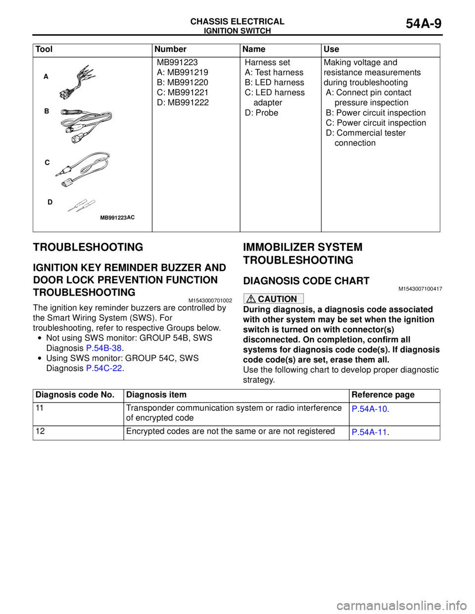
strategy. MB991223
A: MB991219
B: MB991220
C: MB991221
D: MB991222Harness set
A: Test harness
B: LED harness
C: LED harness
adapter
D: ProbeMaking voltage and
resistance measurements
during troubleshooting
A: Connect pin contact
pressure inspection
B: Power circuit inspection
C: Power circuit inspection
D: Commercial tester
connection Tool Number Name Use
MB991223
A
B
C
D
AC
Diagnosis code No. Diagnosis item Reference page
11 Transponder communication system or radio interference
of encrypted codeP.54A-10.
12 Encrypted codes are not the same or are not registered
P.54A-11.