key MITSUBISHI LANCER 2005 Owner's Guide
[x] Cancel search | Manufacturer: MITSUBISHI, Model Year: 2005, Model line: LANCER, Model: MITSUBISHI LANCER 2005Pages: 788, PDF Size: 45.98 MB
Page 411 of 788
IGNITION SWITCH
CHASSIS ELECTRICAL54A-23
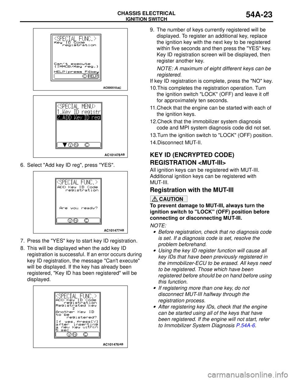
6. Select "Add key ID reg", press "YES".
7. Press the "YES" key to start key ID registration.
8. This will be displayed when the add key ID
registration is successful. If an error occurs during
key ID registration, the message "Can't execute"
will be displayed. If the key has already been
registered, "Key ID has been registered" will be
displayed.9. The number of keys currently registered will be
displayed. To register an additional key, replace
the ignition key with the next key to be registered
within five seconds and then press the "YES" key.
Key ID registration screen will be displayed, then
register another key.
NOTE: A maximum of eight different keys can be
registered.
If key ID registration is complete, press the "NO" key.
10.This completes the registration operation. Turn
the ignition switch "LOCK" (OFF) and leave it off
for approximately ten seconds.
11.Check that the engine can be started with each of
the ignition keys.
12.Check that the immobilizer system diagnosis
code and MPI system diagnosis code did not set.
13.Turn the ignition switch to "LOCK" (OFF) position.
14.Disconnect MUT-II.
KEY ID (ENCRYPTED CODE)
REGISTRATION
All ignition keys can be registered with MUT-III.
Additional ignition keys can be registered with
MUT-III.
Registration with the MUT-III
CAUTION
To prevent damage to MUT-III, always turn the
ignition switch to "LOCK" (OFF) position before
connecting or disconnecting MUT-III.
NOTE: .
•Before registration, check that no diagnosis code
is set. If a diagnosis code is set, resolve the
problem beforehand.
•Using the key ID register function will cause all
key IDs that have been previously registered in
the immobilizer-ECU to be erased. All keys need
to be registered. Those which have been
registered before should be on hand before using
this function.
•If registering more than one key, do not
disconnect MUT-III halfway through the
registration process.
•After registering key IDs, check that the engine
can be started using all of the keys that have
been registered. If the engine will not start, refer
to Immobilizer System Diagnosis P.54A-6.
AC000518AC
AC101478AB
AC101477AB
AC101476AB
Page 412 of 788
IGNITION SWITCH
CHASSIS ELECTRICAL54A-24
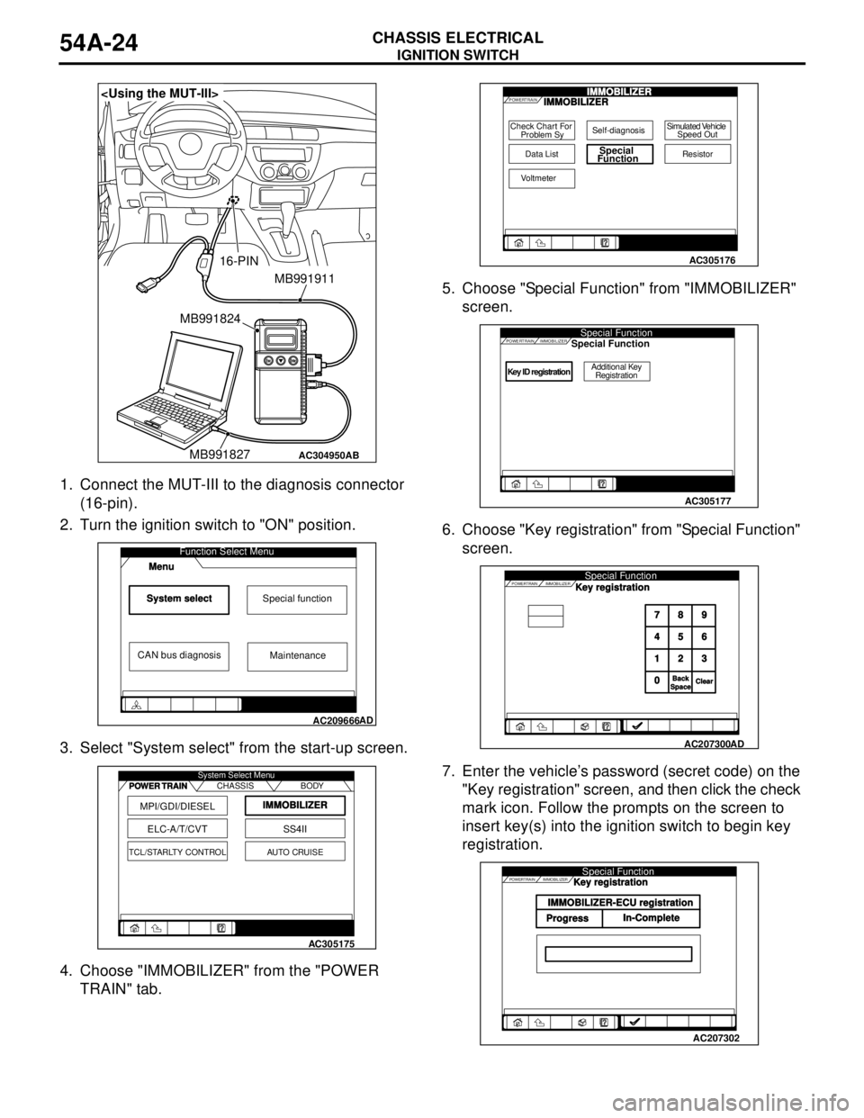
1. Connect the MUT-III to the diagnosis connector
(16-pin).
2. Turn the ignition switch to "ON" position.
3. Select "System select" from the start-up screen.
4. Choose "IMMOBILIZER" from the "POWER
TRAIN" tab.5. Choose "Special Function" from "IMMOBILIZER"
screen.
6. Choose "Key registration" from "Special Function"
screen.
7. Enter the vehicle’s password (secret code) on the
"Key registration" screen, and then click the check
mark icon. Follow the prompts on the screen to
insert key(s) into the ignition switch to begin key
registration.
AC304950
MB991911
16-PIN
MB991827 MB991824
AB
System selectSpecial function
CAN bus diagnosis
Function Select Menu
Menu
AC209666
Maintenance
AD
MPI/GDI/DIESEL
ELC-A/T/CVT
IMMOBILIZER
SS4II
TCL/STARLTY CONTROLAUTO CRUISE CHASSIS BODY System Select Menu
POWER TRAIN
AC305175
Check Chart For
Problem Sy
Data ListSpecial
Function
Self-diagnosisSimulated Vehicle
Speed Out
Resistor
Voltmeter
POWERTRAINIMMOBILIZERIMMOBILIZER
AC305176
Key ID registrationAdditional Key
Registration
POWERTRAINSpecial FunctionIMMOBILIZERSpecial Function
AC305177
POWERTRAIN IMMOBILIZERSpecial Function
789
456
123
0
BackBackSpaceSpaceClearClear
Key registration
AC207300
AD
POWERTRAIN IMMOBILIZERSpecial Function
IMMOBILIZER-ECU registration
ProgressIn-CompleteKey registration
AC207302
Page 413 of 788
IGNITION SWITCH
CHASSIS ELECTRICAL54A-25
8. If the key ID was registered successfully,
"Progress" indication will turn active (gray). Then
the registration process completes. If the key ID
failed to be registered, "In-Complete" indication
will turn active (gray).
9. The number of keys currently registered will be
displayed. To register an additional key, replace
the ignition key with the next key to be registered
within five seconds. Key ID registration screen will
be displayed, then register another key.
NOTE: A maximum of eight different keys can be
registered.
10.This completes the registration operation. Turn
the ignition switch "LOCK" (OFF) and leave it off
for approximately ten seconds.
11.Check that the engine can be started with each of
the ignition keys.
12.Check that the immobilizer system diagnosis
code and MPI system diagnosis code did not set.
13.If not diagnosis code is shown, terminate the
MUT-III.
14.Turn the ignition switch to "LOCK" (OFF) position.
15.Disconnect MUT-III.
Registration of additional keys with the
MUT-III
Additional key(s) can be registered with the MUT-III
while keeping all existing key data.
CAUTION
To prevent damage to MUT-III, always turn the
ignition switch to "LOCK" (OFF) position before
connecting or disconnecting MUT-III.
NOTE: To register additional keys with the MUT-III,
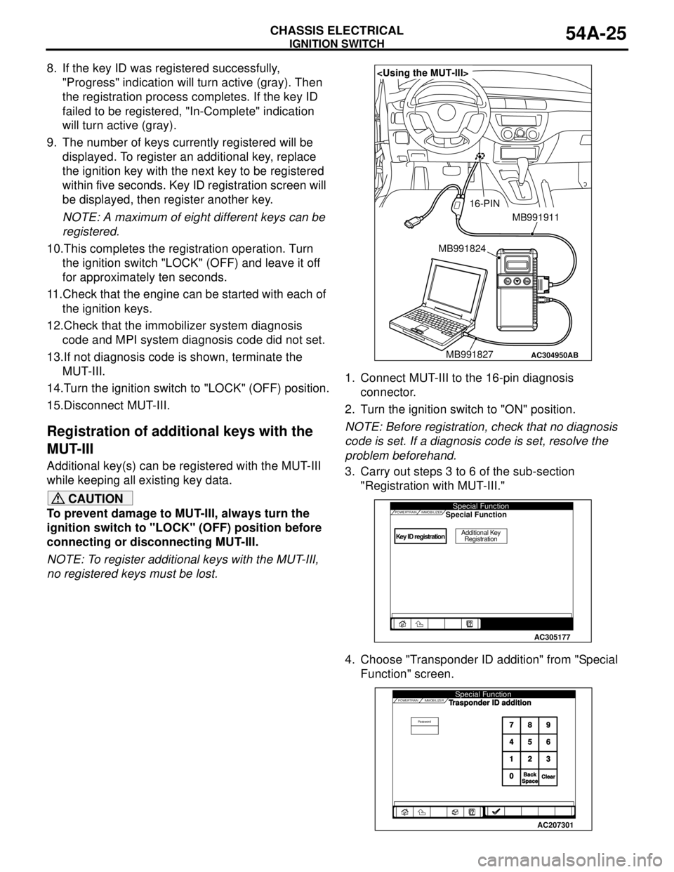
no registered keys must be lost.1. Connect MUT-III to the 16-pin diagnosis
connector.
2. Turn the ignition switch to "ON" position.
NOTE: Before registration, check that no diagnosis
code is set. If a diagnosis code is set, resolve the
problem beforehand.
3. Carry out steps 3 to 6 of the sub-section
"Registration with MUT-III."
4. Choose "Transponder ID addition" from "Special
Function" screen.
AC304950
MB991911
16-PIN
MB991827 MB991824
AB
Key ID registrationAdditional Key
Registration
POWERTRAINSpecial FunctionIMMOBILIZERSpecial Function
AC305177
POWERTRAIN IMMOBILIZER
PasswordSpecial Function
789
456
123
0
BackBackSpaceSpaceClearClear
Trasponder ID addition
AC207301
Page 414 of 788
IGNITION SWITCH
CHASSIS ELECTRICAL54A-26
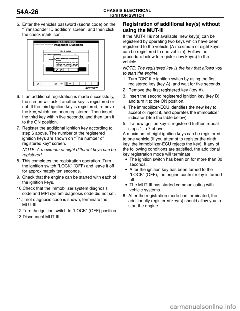
5. Enter the vehicles password (secret code) on the
"Transponder ID addition" screen, and then click
the check mark icon.
6. If an additional registration is made successfully,
the screen will ask if another key is registered or
not. If the third ignition key is registered, remove
the key, which has been registered. Then insert
the third key within five seconds, and then turn it
to the ON position.
7. Register the additional ignition key according to
step 6 above. The number of the registered
ignition keys are shown on "The number of
registered key" screen.
NOTE: A maximum of eight different keys can be
registered.
8. This completes the registration operation. Turn
the ignition switch "LOCK" (OFF) and leave it off
for approximately ten seconds.
9. Check that the engine can be started with each of
the ignition keys.
10.Check that the immobilizer system diagnosis
code and MPI system diagnosis code did not set.
11.If not diagnosis code is shown, terminate the
MUT-III.
12.Turn the ignition switch to "LOCK" (OFF) position.
13.Disconnect MUT-III.Registration of additional key(s) without
using the MUT-III
If the MUT-III is not available, new key(s) can be
registered by operating two keys which have been
registered to the vehicle (A maximum of eight keys
can be registered to one vehicle). Follow the
procedure below to register new key(s) to the
vehicle.
NOTE: The registered key is the key that allows you
to start the engine.
1. Turn "ON" the ignition switch by using the first
registered key (key A), and wait for five seconds.
2. Remove the first registered key (key A).
3. Insert the second registered ignition key (key B),
and turn it to the ON position.
4. The immobilizer-ECU identifies the new key to
accept or reject it, and operates the immobilizer
indicator (See the table below).
5. If a new ignition key is registered further, repeat
steps 1 to 7 above.
A maximum of eight ignition keys can be registered
to one vehicle (If you attempt to register the ninth
key, the immobilizer-ECU rejects the key). If any of
the following conditions are satisfied, the additional
key registration mode will terminate:
•The ignition switch has been on for more than 30
seconds.
•After the ignition key has been turned to the
"LOCK" (OFF), the engine control relay is turned
off.
•The MUT-III has started communicating with
vehicle systems.
6. After the registration mode has terminated, the
additionally registered key(s) should allow you to
start the engine.
AC207301
AC209775POWERTRAIN IMMOBILIZER
Key ID registerey ID registerThe number of registered keyThe number of registered key3
Progre
Progre
Special FunctionTrasponder ID addition
About Additional TAbout Additional TransponderransponderID SETID SETIf register another key ID, press theIf register another key ID, press theOK button after inserting a new keyOK button after inserting a new keywithin 5 sec and turning on IG-SWwithin 5 sec and turning on IG-SW.
Page 415 of 788
IGNITION SWITCH
CHASSIS ELECTRICAL54A-27
IGNITION SWITCH
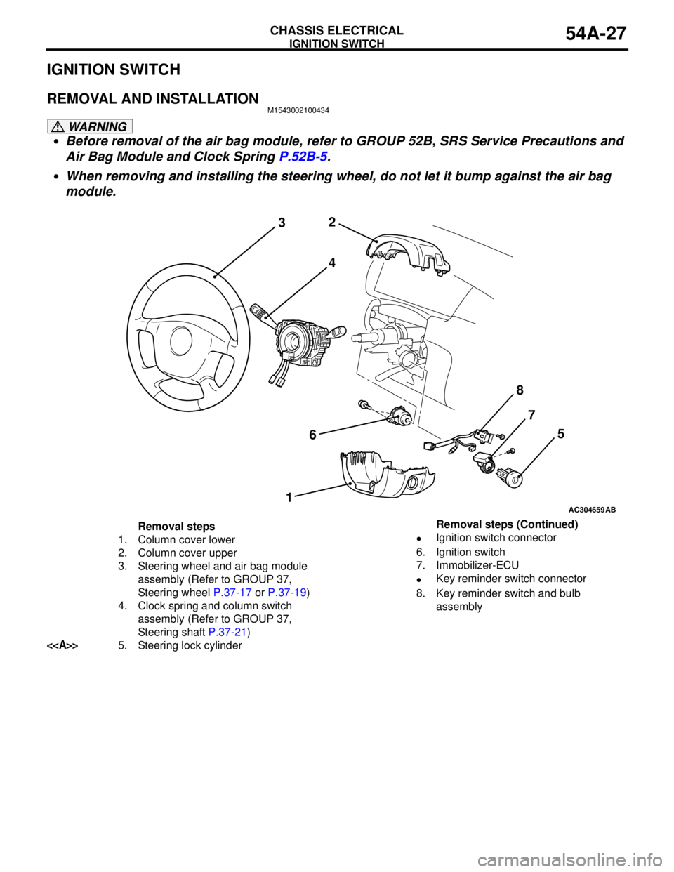
REMOVAL AND INSTALLATIONM1543002100434
WARNING
•Before removal of the air bag module, refer to GROUP 52B, SRS Service Precautions and
Air Bag Module and Clock Spring P.52B-5.
•When removing and installing the steering wheel, do not let it bump against the air bag
module.
AC304659
2
3
4
67
15
AB
8
Removal steps
1. Column cover lower
2. Column cover upper
3. Steering wheel and air bag module
assembly (Refer to GROUP 37,
Steering wheel P.37-17 or P.37-19)
4. Clock spring and column switch
assembly (Refer to GROUP 37,
Steering shaft P.37-21)
<>5. Steering lock cylinder•Ignition switch connector
6. Ignition switch
7. Immobilizer-ECU
•Key reminder switch connector
8. Key reminder switch and bulb
assembly Removal steps (Continued)
Page 416 of 788
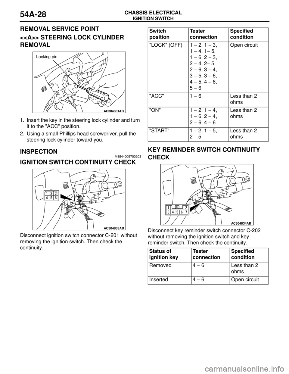
Page 466 of 788
ROOM LAMP
CHASSIS ELECTRICAL54A-78
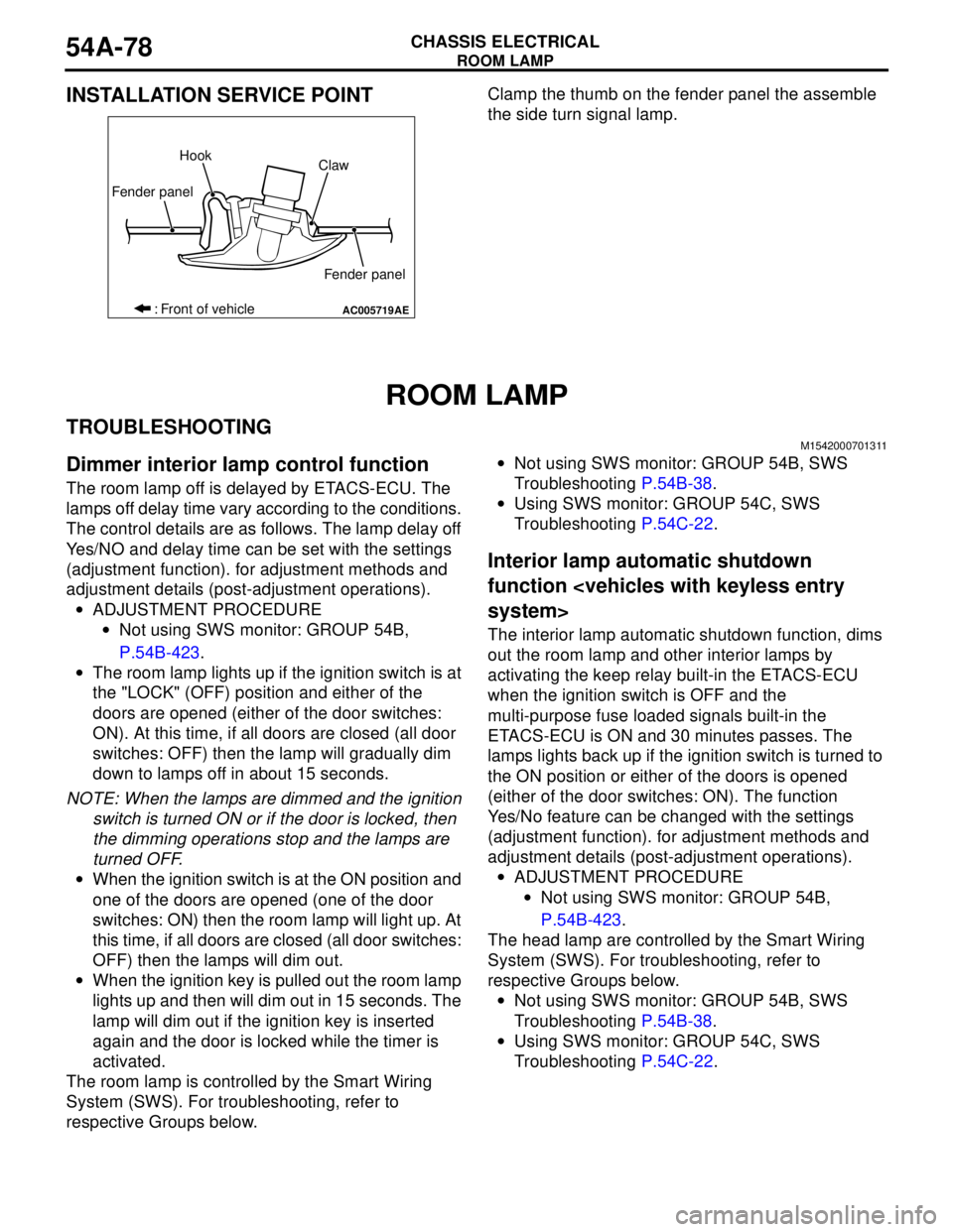
INSTALLATION SERVICE POINTClamp the thumb on the fender panel the assemble
the side turn signal lamp.
ROOM LAMP
TROUBLESHOOTINGM1542000701311
Dimmer interior lamp control function
The room lamp off is delayed by ETACS-ECU. The
lamps off delay time vary according to the conditions.
The control details are as follows. The lamp delay off
Yes/NO and delay time can be set with the settings
(adjustment function). for adjustment methods and
adjustment details (post-adjustment operations).
•ADJUSTMENT PROCEDURE
•Not using SWS monitor: GROUP 54B,
P.54B-423.
•The room lamp lights up if the ignition switch is at
the "LOCK" (OFF) position and either of the
doors are opened (either of the door switches:
ON). At this time, if all doors are closed (all door
switches: OFF) then the lamp will gradually dim
down to lamps off in about 15 seconds.
NOTE: When the lamps are dimmed and the ignition
switch is turned ON or if the door is locked, then
the dimming operations stop and the lamps are
turned OFF.
•When the ignition switch is at the ON position and
one of the doors are opened (one of the door
switches: ON) then the room lamp will light up. At
this time, if all doors are closed (all door switches:
OFF) then the lamps will dim out.
•When the ignition key is pulled out the room lamp
lights up and then will dim out in 15 seconds. The
lamp will dim out if the ignition key is inserted
again and the door is locked while the timer is
activated.
The room lamp is controlled by the Smart Wiring
System (SWS). For troubleshooting, refer to
respective Groups below.•Not using SWS monitor: GROUP 54B, SWS
Troubleshooting P.54B-38.
•Using SWS monitor: GROUP 54C, SWS
Troubleshooting P.54C-22.
Interior lamp automatic shutdown
function
The interior lamp automatic shutdown function, dims
out the room lamp and other interior lamps by
activating the keep relay built-in the ETACS-ECU
when the ignition switch is OFF and the
multi-purpose fuse loaded signals built-in the
ETACS-ECU is ON and 30 minutes passes. The
lamps lights back up if the ignition switch is turned to
the ON position or either of the doors is opened
(either of the door switches: ON). The function
Yes/No feature can be changed with the settings
(adjustment function). for adjustment methods and
adjustment details (post-adjustment operations).
•ADJUSTMENT PROCEDURE
•Not using SWS monitor: GROUP 54B,
P.54B-423.
The head lamp are controlled by the Smart Wiring
System (SWS). For troubleshooting, refer to
respective Groups below.
•Not using SWS monitor: GROUP 54B, SWS
Troubleshooting P.54B-38.
•Using SWS monitor: GROUP 54C, SWS
Troubleshooting P.54C-22.
AC005719
Fender panelHook
Claw
Fender panel
: Front of vehicle
AE
Page 624 of 788
DASH PANEL
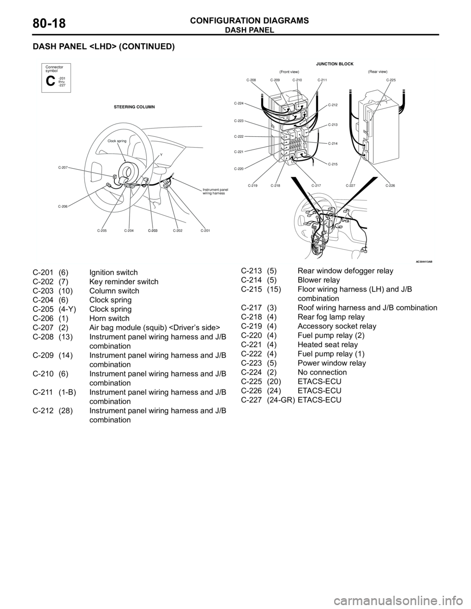
CONFIGURATION DIAGRAMS80-18
DASH PANEL
AC304413
Connector
symbol
-201
thru
-227C
STEERING COLUMN
C-207
C-206
C-201 C-202 C-203
C-203 C-204 C-205Instrument panel
wiring harness
Clock spring
Y
AB
(Front view)(Rear view)
C-208 C-209 C-210 C-211
C-212
C-213
C-214
C-215
C-217 C-218 C-219 C-220 C-221 C-222 C-223 C-224C-225
C-226 C-227
JUNCTION BLOCK
C-201 (6) Ignition switch
C-202 (7) Key reminder switch
C-203 (10) Column switch
C-204 (6) Clock spring
C-205 (4-Y) Clock spring
C-206 (1) Horn switch
C-207 (2) Air bag module (squib)
C-208 (13) Instrument panel wiring harness and J/B
combination
C-209 (14) Instrument panel wiring harness and J/B
combination
C-210 (6) Instrument panel wiring harness and J/B
combination
C-211 (1-B) Instrument panel wiring harness and J/B
combination
C-212 (28) Instrument panel wiring harness and J/B
combinationC-213 (5) Rear window defogger relay
C-214 (5) Blower relay
C-215 (15) Floor wiring harness (LH) and J/B
combination
C-217 (3) Roof wiring harness and J/B combination
C-218 (4) Rear fog lamp relay
C-219 (4) Accessory socket relay
C-220 (4) Fuel pump relay (2)
C-221 (4) Heated seat relay
C-222 (4) Fuel pump relay (1)
C-223 (5) Power window relay
C-224 (2) No connection
C-225 (20) ETACS-ECU
C-226 (24) ETACS-ECU
C-227 (24-GR) ETACS-ECU
Page 627 of 788
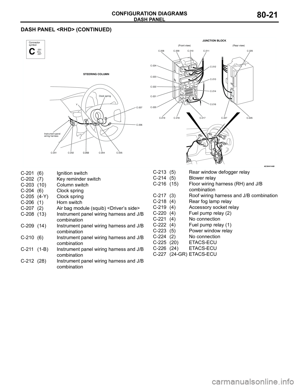
DASH PANEL
CONFIGURATION DIAGRAMS80-21
DASH PANEL
AC304414AB
(Front view)(Rear view)
C-208 C-209 C-210 C-211
C-212
C-213
C-214
C-216
C-217 C-218 C-219 C-220 C-221 C-222 C-223 C-224C-225
C-226 C-227
JUNCTION BLOCKConnector
symbol
-201
thru
-227C
STEERING COLUMN
C-207
C-206
C-205 C-204 C-203
C-203 C-202 C-201 Instrument panel
wiring harness
Clock spring
Y
C-201 (6) Ignition switch
C-202 (7) Key reminder switch
C-203 (10) Column switch
C-204 (6) Clock spring
C-205 (4-Y) Clock spring
C-206 (1) Horn switch
C-207 (2) Air bag module (squib)
C-208 (13) Instrument panel wiring harness and J/B
combination
C-209 (14) Instrument panel wiring harness and J/B
combination
C-210 (6) Instrument panel wiring harness and J/B
combination
C-211 (1-B) Instrument panel wiring harness and J/B
combination
C-212 (28) Instrument panel wiring harness and J/B
combinationC-213 (5) Rear window defogger relay
C-214 (5) Blower relay
C-216 (15) Floor wiring harness (RH) and J/B
combination
C-217 (3) Roof wiring harness and J/B combination
C-218 (4) Rear fog lamp relay
C-219 (4) Accessory socket relay
C-220 (4) Fuel pump relay (2)
C-221 (4) No connection
C-222 (4) Fuel pump relay (1)
C-223 (5) Power window relay
C-224 (2) No connection
C-225 (20) ETACS-ECU
C-226 (24) ETACS-ECU
C-227 (24-GR) ETACS-ECU
Page 632 of 788
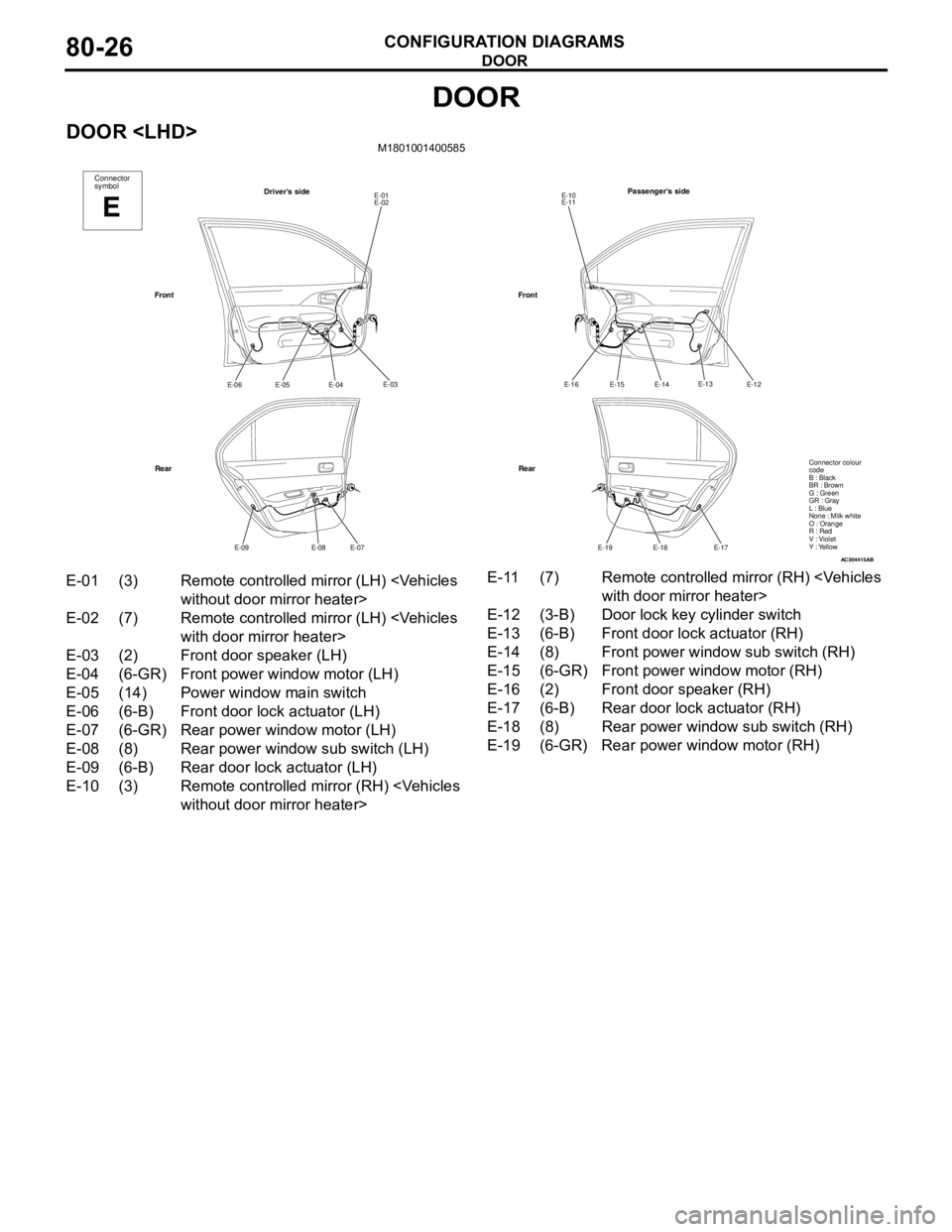
DOOR
CONFIGURATION DIAGRAMS80-26
DOOR
DOOR
AC304415
Connector
symbol
E
Driver's sideE-01
E-02
E-03
E-04
E-05 E-06
E-07
E-08 E-09
Front
RearPassenger's side
E-10
E-11
E-12
E-14
E-15 E-16
E-17
E-18 E-19
Front
Rear
AB
E-13
Connector colour
code
B : Black
BR : Brown
G : Green
GR : Gray
L : Blue
None : Milk white
O : Orange
R : Red
V : Violet
Y : Yellow
E-01 (3) Remote controlled mirror (LH)
E-02 (7) Remote controlled mirror (LH)
E-03 (2) Front door speaker (LH)
E-04 (6-GR) Front power window motor (LH)
E-05 (14) Power window main switch
E-06 (6-B) Front door lock actuator (LH)
E-07 (6-GR) Rear power window motor (LH)
E-08 (8) Rear power window sub switch (LH)
E-09 (6-B) Rear door lock actuator (LH)
E-10 (3) Remote controlled mirror (RH)
E-12 (3-B) Door lock key cylinder switch
E-13 (6-B) Front door lock actuator (RH)
E-14 (8) Front power window sub switch (RH)
E-15 (6-GR) Front power window motor (RH)
E-16 (2) Front door speaker (RH)
E-17 (6-B) Rear door lock actuator (RH)
E-18 (8) Rear power window sub switch (RH)
E-19 (6-GR) Rear power window motor (RH)