speedom MITSUBISHI LANCER 2005 User Guide
[x] Cancel search | Manufacturer: MITSUBISHI, Model Year: 2005, Model line: LANCER, Model: MITSUBISHI LANCER 2005Pages: 788, PDF Size: 45.98 MB
Page 431 of 788
COMBINATION METER ASSEMBLY
CHASSIS ELECTRICAL54A-43
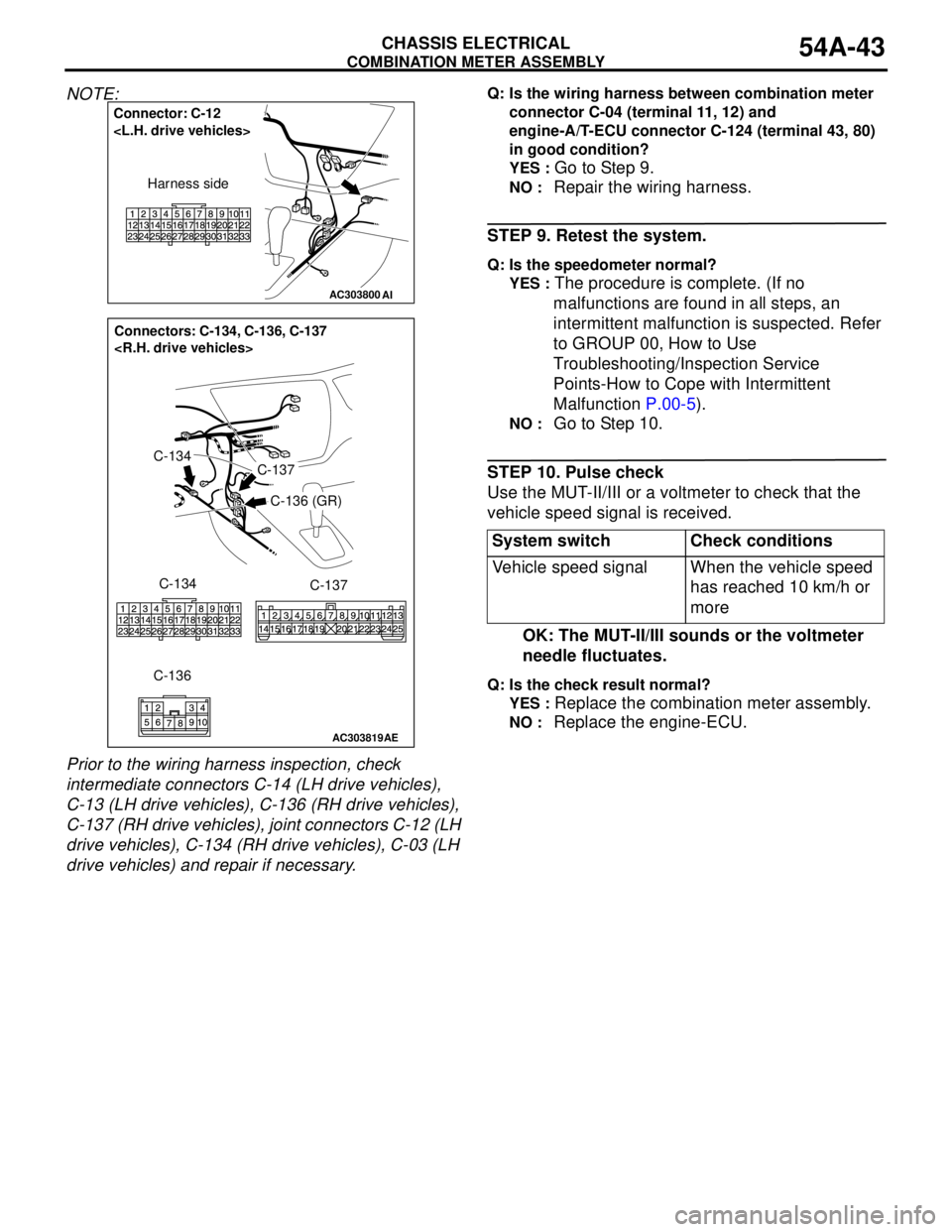
NOTE:
Prior to the wiring harness inspection, check
intermediate connectors C-14 (LH drive vehicles),
C-13 (LH drive vehicles), C-136 (RH drive vehicles),
C-137 (RH drive vehicles), joint connectors C-12 (LH
drive vehicles), C-134 (RH drive vehicles), C-03 (LH
drive vehicles) and repair if necessary.Q: Is the wiring harness between combination meter
connector C-04 (terminal 11, 12) and
engine-A/T-ECU connector C-124 (terminal 43, 80)
in good condition?
YES :
Go to Step 9.
NO : Repair the wiring harness.
STEP 9. Retest the system.
Q: Is the speedometer normal?
YES :
The procedure is complete. (If no
malfunctions are found in all steps, an
intermittent malfunction is suspected. Refer
to GROUP 00, How to Use
Troubleshooting/Inspection Service
Points-How to Cope with Intermittent
Malfunction P.00-5).
NO : Go to Step 10.
STEP 10. Pulse check
Use the MUT-II/III or a voltmeter to check that the
vehicle speed signal is received.
OK: The MUT-II/III sounds or the voltmeter
needle fluctuates.
Q: Is the check result normal?
YES :
Replace the combination meter assembly.
NO : Replace the engine-ECU.
AC303800
Connector: C-12
Harness side
AI
AC303819
Connectors: C-134, C-136, C-137
C-134
AE
C-134
C-136C-137
C-136 (GR)
C-137
System switch Check conditions
Vehicle speed signal When the vehicle speed
has reached 10 km/h or
more
Page 448 of 788
COMBINATION METER ASSEMBLY
CHASSIS ELECTRICAL54A-60
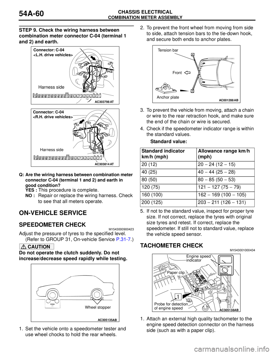
STEP 9. Check the wiring harness between
combination meter connector C-04 (terminal 1
and 2) and earth.
Q: Are the wiring harness between combination meter
connector C-04 (terminal 1 and 2) and earth in
good condition?
YES :
This procedure is complete.
NO : Repair or replace the wiring harness. Check
to see that all meters operate.
ON-VEHICLE SERVICE
SPEEDOMETER CHECKM1543000900423
Adjust the pressure of tyres to the specified level.
(Refer to GROUP 31, On-vehicle Service P.31-7.)
CAUTION
Do not operate the clutch suddenly. Do not
increase/decrease speed rapidly while testing.
1. Set the vehicle onto a speedometer tester and
use wheel chocks to hold the rear wheels.2. To prevent the front wheel from moving from side
to side, attach tension bars to the tie-down hook,
and secure both ends to anchor plates.
3. To prevent the vehicle from moving, attach a chain
or wire to the rear retraction hook, and make sure
the end of the chain or wire is secured.
4. Check if the speedometer indicator range is within
the standard values.
Standard value:
5. If not to the standard value, inspect for proper tyre
size. If not correct, replace the tyres with original
size tyres and retest. If correct, replace the
speedometer. If still not to standard value, replace
the vehicle speed sensor.
TACHOMETER CHECKM1543001000434
1. Attach an external high quality tachometer to the
engine speed detection connector on the harness
side (such as with a paper clip).
AC303798
Connector: C-04
Harness side
AT
AC303814
Connector: C-04
Harness side
AT
AC305135AB
Wheel stopper
Standard indicator
km/h (mph)Allowance range km/h
(mph)
20 (12) 20 − 24 (12 − 15)
40 (25) 40 − 44 (25 − 28)
80 (50) 80 − 85 (50 − 53)
120 (75) 121 − 127 (75 − 79)
160 (100) 162 − 169 (100 − 105)
200 (125) 203 − 211 (126 − 131)
AC001288
Tension bar
Front
Anchor plate
AB
AC305138AB
Engine speed
indicator
Paper clip
Probe for detection
of engine speed