wheel bolts MITSUBISHI LANCER 2005 Workshop Manual
[x] Cancel search | Manufacturer: MITSUBISHI, Model Year: 2005, Model line: LANCER, Model: MITSUBISHI LANCER 2005Pages: 788, PDF Size: 45.98 MB
Page 139 of 788

ON-VEHICLE SERVICE
FRONT AXLE26-7
ON-VEHICLE SERVICE
WHEEL BEARING AXIAL PLAY CHECKM1261000900224
1. Remove the caliper assembly and suspend it with
a wire.
2. Remove the brake disc from the front hub.
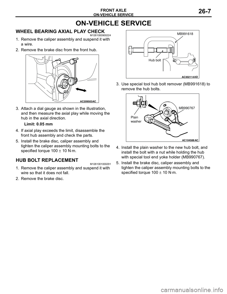
3. Attach a dial gauge as shown in the illustration,
and then measure the axial play while moving the
hub in the axial direction.
Limit: 0.05 mm
4. If axial play exceeds the limit, disassemble the
front hub assembly and check the parts.
5. Install the brake disc, caliper assembly and
tighten the caliper assembly mounting bolts to the
specified torque 100 ± 10 N⋅m.
HUB BOLT REPLACEMENTM1261001000291
1. Remove the caliper assembly and suspend it with
wire so that it does not fall.
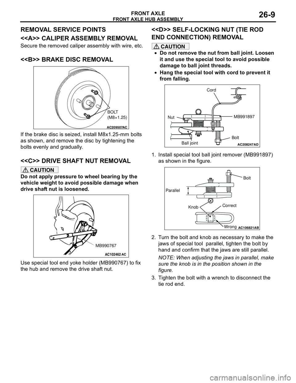
2. Remove the brake disc.3. Use special tool hub bolt remover (MB991618) to
remove the hub bolts.
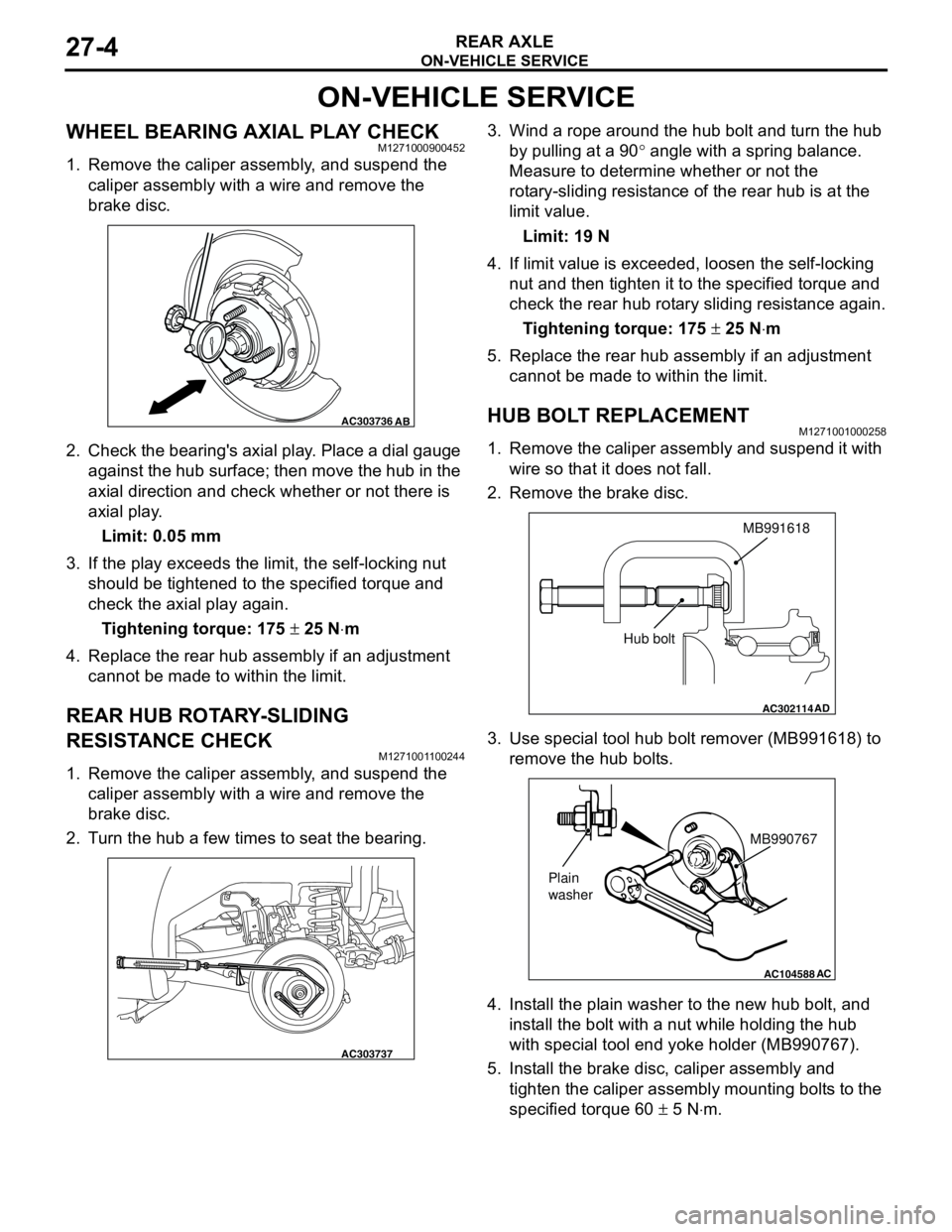
4. Install the plain washer to the new hub bolt, and
install the bolt with a nut while holding the hub
with special tool end yoke holder (MB990767).
5. Install the brake disc, caliper assembly and
tighten the caliper assembly mounting bolts to the
specified torque 100 ± 10 N⋅m.
AC209503AC
AC302114
MB991618
AD
Hub bolt
AC104588
MB990767
Plain
washer
AC
Page 141 of 788

Page 160 of 788

ON-VEHICLE SERVICE
REAR AXLE27-4
ON-VEHICLE SERVICE
WHEEL BEARING AXIAL PLAY CHECKM1271000900452
1. Remove the caliper assembly, and suspend the
caliper assembly with a wire and remove the
brake disc.
2. Check the bearing's axial play. Place a dial gauge
against the hub surface; then move the hub in the
axial direction and check whether or not there is
axial play.
Limit: 0.05 mm
3. If the play exceeds the limit, the self-locking nut
should be tightened to the specified torque and
check the axial play again.
Tightening torque: 175 ± 25 N⋅m
4. Replace the rear hub assembly if an adjustment
cannot be made to within the limit.
REAR HUB ROTARY-SLIDING
RESISTANCE CHECK
M1271001100244
1. Remove the caliper assembly, and suspend the
caliper assembly with a wire and remove the
brake disc.
2. Turn the hub a few times to seat the bearing.3. Wind a rope around the hub bolt and turn the hub
by pulling at a 90° angle with a spring balance.
Measure to determine whether or not the
rotary-sliding resistance of the rear hub is at the
limit value.
Limit: 19 N
4. If limit value is exceeded, loosen the self-locking
nut and then tighten it to the specified torque and
check the rear hub rotary sliding resistance again.
Tightening torque: 175 ± 25 N⋅m
5. Replace the rear hub assembly if an adjustment
cannot be made to within the limit.
HUB BOLT REPLACEMENTM1271001000258
1. Remove the caliper assembly and suspend it with
wire so that it does not fall.
2. Remove the brake disc.
3. Use special tool hub bolt remover (MB991618) to
remove the hub bolts.
4. Install the plain washer to the new hub bolt, and
install the bolt with a nut while holding the hub
with special tool end yoke holder (MB990767).
5. Install the brake disc, caliper assembly and
tighten the caliper assembly mounting bolts to the
specified torque 60 ± 5 N⋅m.
AC303736AB
AC303737
AC302114
MB991618
AD
Hub bolt
AC104588
MB990767
Plain
washer
AC
Page 255 of 788

STEERING SHAFT
POWER STEERING37-21
STEERING SHAFT
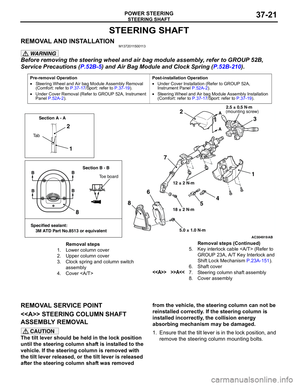
REMOVAL AND INSTALLATIONM1372011500113
WARNING
Before removing the steering wheel and air bag module assembly, refer to GROUP 52B,
Service Precautions (P.52B-5) and Air Bag Module and Clock Spring (P.52B-210).
REMOVAL SERVICE POINT
<> STEERING COLUMN SHAFT
ASSEMBLY REMOVAL
CAUTION
The tilt lever should be held in the lock position
until the steering column shaft is installed to the
vehicle. If the steering column is removed with
the tilt lever released, or the tilt lever is released
after the steering column shaft was removed from the vehicle, the steering column can not be
reinstalled correctly. If the steering column is
installed incorrectly, the collision energy
absorbing mechanism may be damaged.
1. Ensure that the tilt lever is in the lock position, and
remove the steering column mounting bolts.
Pre-removal Operation
•Steering Wheel and Air bag Module Assembly Removal
(Comfort: refer to P.37-17/Sport: refer to P.37-19).
•Under Cover Removal (Refer to GROUP 52A, Instrument
Panel P.52A-2).Post-installation Operation
•Under Cover Installation (Refer to GROUP 52A,
Instrument Panel P.52A-2).
•Steering Wheel and Air bag Module Assembly Installation
(Comfort: refer to P.37-17/Sport: refer to P.37-19).
AC304919AB
12 ± 2 N·m
18 ± 2 N·m
5.0 ± 1.0 N·m
1 2
73 2
1
8
86
A
A
Ta bSection A - A
Section B - B
BB
Toe board
Specified sealant:
3M ATD Part No.8513 or equivalent
BB
4
5
(mounting screw)2.5 ± 0.5 N·m
Removal steps
1. Lower column cover
2. Upper column cover
3. Clock spring and column switch
assembly
4. Cover 5. Key interlock cable (Refer to
GROUP 23A, A/T Key Interlock and
Shift Lock Mechanism P.23A-151).
6. Shaft cover
<> >>A<<7. Steering column shaft assembly
8. Cover assemblyRemoval steps (Continued)