throttle body MITSUBISHI LANCER 2005 User Guide
[x] Cancel search | Manufacturer: MITSUBISHI, Model Year: 2005, Model line: LANCER, Model: MITSUBISHI LANCER 2005Pages: 788, PDF Size: 45.98 MB
Page 124 of 788
EMISSION CONTROL
ENGINE AND EMISSION CONTROL17-16
5. Replace the gasket, and tighten to the specified
torque.
Tightening torque:
<4G1> 21 ± 4 N⋅m
<4G6> 20 ± 2 N⋅m
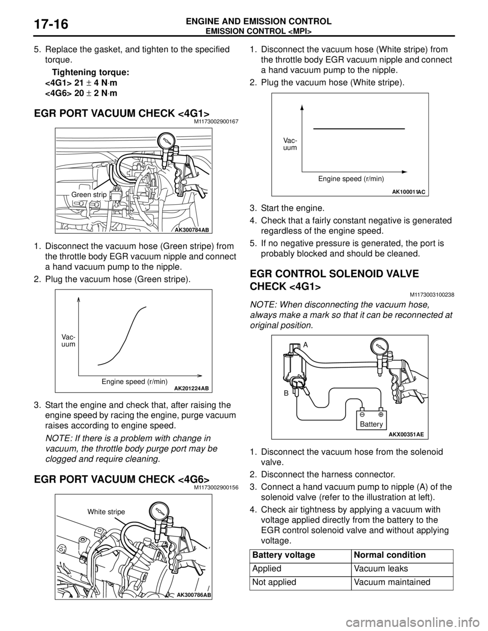
EGR PORT VACUUM CHECK <4G1>M1173002900167
1. Disconnect the vacuum hose (Green stripe) from
the throttle body EGR vacuum nipple and connect
a hand vacuum pump to the nipple.
2. Plug the vacuum hose (Green stripe).
3. Start the engine and check that, after raising the
engine speed by racing the engine, purge vacuum
raises according to engine speed.
NOTE: If there is a problem with change in
vacuum, the throttle body purge port may be
clogged and require cleaning.
EGR PORT VACUUM CHECK <4G6>M1173002900156
1. Disconnect the vacuum hose (White stripe) from
the throttle body EGR vacuum nipple and connect
a hand vacuum pump to the nipple.
2. Plug the vacuum hose (White stripe).
3. Start the engine.
4. Check that a fairly constant negative is generated
regardless of the engine speed.
5. If no negative pressure is generated, the port is
probably blocked and should be cleaned.
EGR CONTROL SOLENOID VALVE
CHECK <4G1>
M1173003100238
NOTE: When disconnecting the vacuum hose,
always make a mark so that it can be reconnected at
original position.
1. Disconnect the vacuum hose from the solenoid
valve.
2. Disconnect the harness connector.
3. Connect a hand vacuum pump to nipple (A) of the
solenoid valve (refer to the illustration at left).
4. Check air tightness by applying a vacuum with
voltage applied directly from the battery to the
EGR control solenoid valve and without applying
voltage.
AK300784AB
Green strip
AK201224AB
Vac-
uum
Engine speed (r/min)
AK300786AB
White stripe
Battery voltage Normal condition
Applied Vacuum leaks
Not applied Vacuum maintained
AK100011AC
Vac-
uum
Engine speed (r/min)
AKX00351
A
B
AE
Battery
Page 592 of 788
SENSOR
COMPONENT LOCATIONS70-6
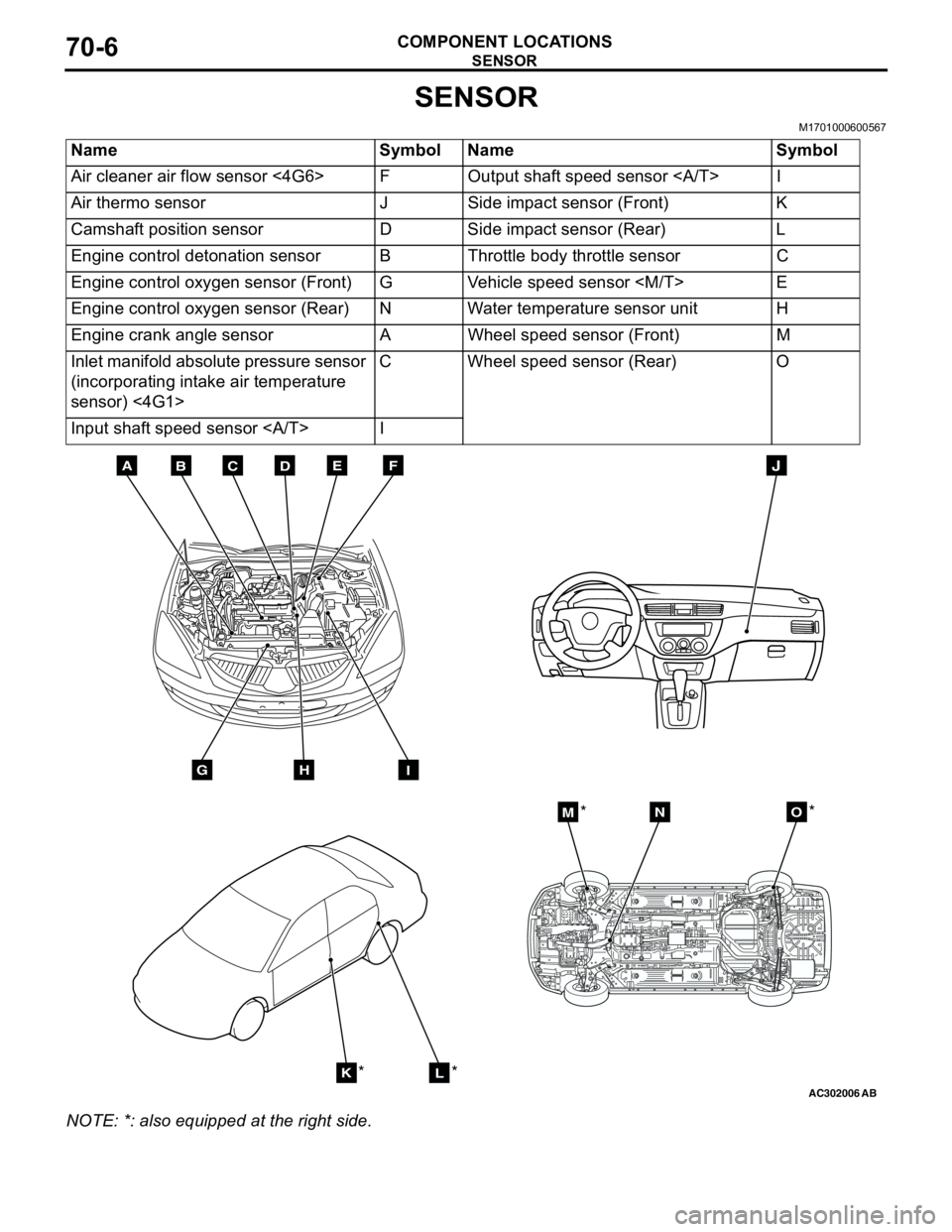
SENSOR
M1701000600567
NOTE: *: also equipped at the right side.Name Symbol Name Symbol
Air cleaner air flow sensor <4G6> F Output shaft speed sensor I
Air thermo sensor J Side impact sensor (Front) K
Camshaft position sensor D Side impact sensor (Rear) L
Engine control detonation sensor B Throttle body throttle sensor C
Engine control oxygen sensor (Front) G Vehicle speed sensor
Engine control oxygen sensor (Rear) N Water temperature sensor unit H
Engine crank angle sensor A Wheel speed sensor (Front) M
Inlet manifold absolute pressure sensor
(incorporating intake air temperature
sensor) <4G1>C Wheel speed sensor (Rear) O
Input shaft speed sensor I
AC302006AB
BDCFEA
GHI
J
KL
MNO
*
***
Page 593 of 788
SENSOR
COMPONENT LOCATIONS70-7
AC208762
A
AD
Timing belt front
upper coverTiming belt front
lower coverEngine crank
angle sensor
<4G1>
Engine crank angle
sensor connector
AC302008
A<4G6>
ABHeat protector
Crankshaft
sprocket
Engine crank angle
sensor connectorEngine crank
angle sensor
AC301752
B
AB
Ignition coil 2
<4G1>
Engine control detonation
sensor connector
Engine control
detonation sensor
AC302009
B
AB
Hydraulic unit
<4G6>
Alternator
Engine control detonation
sensor connectorEngine control
detonation sensor
AC208541
C
AE
<4G1>
Throttle body
Throttle body
throttle sensor
Inlet manifold absolute pressure sensor
(incorporating intake air temperature sensor)
AC302479
AB
C
Throttle body
<4G6>
Throttle body
throttle sensor
Page 597 of 788
EARTH CABLE
COMPONENT LOCATIONS70-11
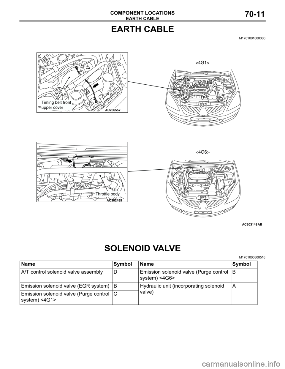
EARTH CABLE
M1701001000308
SOLENOID VALVE
M1701000800516
AC303148
AC206557
AC302485
AB
Timing belt front
upper cover
Throttle body
<4G1>
<4G6>
Name Symbol Name Symbol
A/T control solenoid valve assembly D Emission solenoid valve (Purge control
system) <4G6>B
Emission solenoid valve (EGR system) B Hydraulic unit (incorporating solenoid
valve)A
Emission solenoid valve (Purge control
system) <4G1>C
Page 614 of 788
ENGINE AND TRANSMISSION
CONFIGURATION DIAGRAMS80-8
ENGINE AND TRANSMISSION
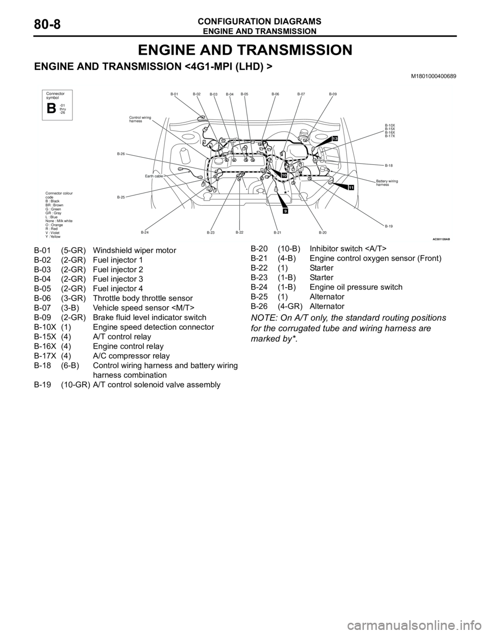
ENGINE AND TRANSMISSION <4G1-MPI (LHD) >M1801000400689
NOTE: On A/T only, the standard routing positions
for the corrugated tube and wiring harness are
marked by*.
AC301128
B-02
B-03B-04B-05
B-22
B-23 B-24 B-25 B-26Control wiring
harnessB-01
Connector colour
code
B : Black
BR : Brown
G : Green
GR : Gray
L : Blue
None : Milk white
O : Orange
R : Red
V : Violet
Y : Yellow*
Connector
symbol
-01
thru
-26B
Earth cable
AB
9
10
11
13
B-06B-07
B-09
B-10X
B-15X
B-16X
B-17X
B-18
Battery wiring
harness
B-19
B-20
B-21
*
B-01 (5-GR) Windshield wiper motor
B-02 (2-GR) Fuel injector 1
B-03 (2-GR) Fuel injector 2
B-04 (2-GR) Fuel injector 3
B-05 (2-GR) Fuel injector 4
B-06 (3-GR) Throttle body throttle sensor
B-07 (3-B) Vehicle speed sensor
B-09 (2-GR) Brake fluid level indicator switch
B-10X (1) Engine speed detection connector
B-15X (4) A/T control relay
B-16X (4) Engine control relay
B-17X (4) A/C compressor relay
B-18 (6-B) Control wiring harness and battery wiring
harness combination
B-19 (10-GR) A/T control solenoid valve assemblyB-20 (10-B) Inhibitor switch
B-21 (4-B) Engine control oxygen sensor (Front)
B-22 (1) Starter
B-23 (1-B) Starter
B-24 (1-B) Engine oil pressure switch
B-25 (1) Alternator
B-26 (4-GR) Alternator
Page 615 of 788
ENGINE AND TRANSMISSION
CONFIGURATION DIAGRAMS80-9
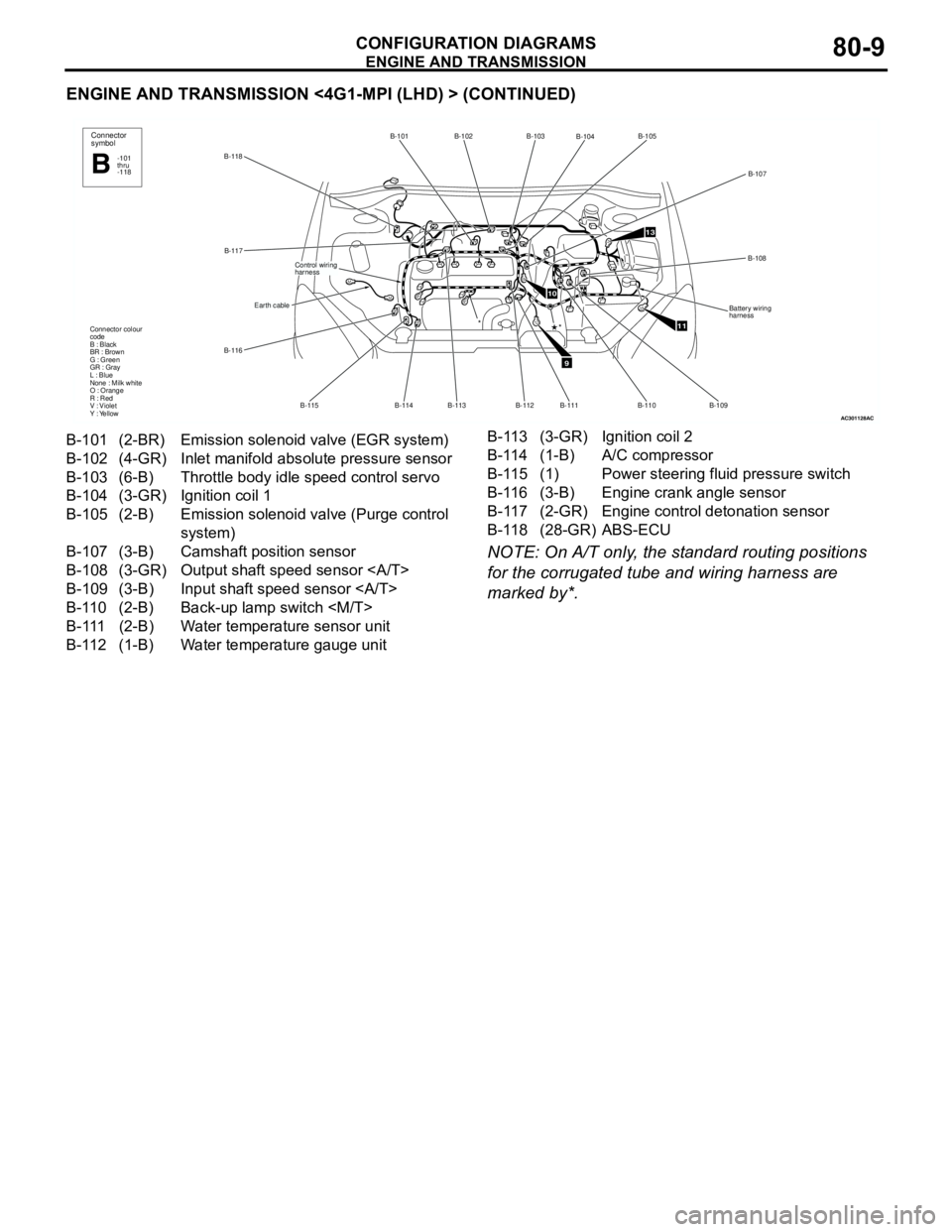
ENGINE AND TRANSMISSION <4G1-MPI (LHD) > (CONTINUED)
NOTE: On A/T only, the standard routing positions
for the corrugated tube and wiring harness are
marked by*.
AC301128
B-118B-101 B-102
B-113
B-114 B-115 B-116B-117
Earth cable
Control wiring
harness
Connector colour
code
B : Black
BR : Brown
G : Green
GR : Gray
L : Blue
None : Milk white
O : Orange
R : Red
V : Violet
Y : Yellow
Connector
symbol
-101
thru
-118B
*
AC
9
10
11
13
B-103
B-104B-105
B-107
B-108
Battery wiring
harness
B-109
B-110 B-111
*
B-112
B-101 (2-BR) Emission solenoid valve (EGR system)
B-102 (4-GR) Inlet manifold absolute pressure sensor
B-103 (6-B) Throttle body idle speed control servo
B-104 (3-GR) Ignition coil 1
B-105 (2-B) Emission solenoid valve (Purge control
system)
B-107 (3-B) Camshaft position sensor
B-108 (3-GR) Output shaft speed sensor
B-109 (3-B) Input shaft speed sensor
B-110 (2-B) Back-up lamp switch
B-111 (2-B) Water temperature sensor unit
B-112 (1-B) Water temperature gauge unitB-113 (3-GR) Ignition coil 2
B-114 (1-B) A/C compressor
B-115 (1) Power steering fluid pressure switch
B-116 (3-B) Engine crank angle sensor
B-117 (2-GR) Engine control detonation sensor
B-118 (28-GR) ABS-ECU
Page 616 of 788
ENGINE AND TRANSMISSION
CONFIGURATION DIAGRAMS80-10
ENGINE AND TRANSMISSION
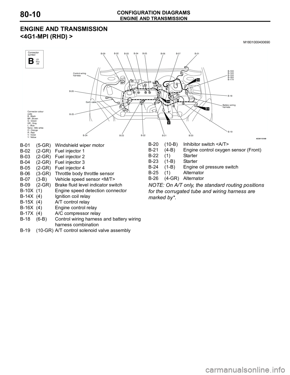
<4G1-MPI (RHD) >
M1801000400690
NOTE: On A/T only, the standard routing positions
for the corrugated tube and wiring harness are
marked by*.
AC301131
B-02
B-03B-04 B-05
B-22
B-23 B-24 B-25 B-26Control wiring
harnessB-09
Connector colour
code
B : Black
BR : Brown
G : Green
GR : Gray
L : Blue
None : Milk white
O : Orange
R : Red
V : Violet
Y : Yellow*
Connector
symbol
-01
thru
-26B
Earth cable
AB
9
10
11
13
B-06B-07
B-01
B-10X
B-14X
B-15X
B-16X
B-17X
B-18
Battery wiring
harness
B-19
B-20 B-21
*
B-01 (5-GR) Windshield wiper motor
B-02 (2-GR) Fuel injector 1
B-03 (2-GR) Fuel injector 2
B-04 (2-GR) Fuel injector 3
B-05 (2-GR) Fuel injector 4
B-06 (3-GR) Throttle body throttle sensor
B-07 (3-B) Vehicle speed sensor
B-09 (2-GR) Brake fluid level indicator switch
B-10X (1) Engine speed detection connector
B-14X (4) Ignition coil relay
B-15X (4) A/T control relay
B-16X (4) Engine control relay
B-17X (4) A/C compressor relay
B-18 (6-B) Control wiring harness and battery wiring
harness combination
B-19 (10-GR) A/T control solenoid valve assemblyB-20 (10-B) Inhibitor switch
B-21 (4-B) Engine control oxygen sensor (Front)
B-22 (1) Starter
B-23 (1-B) Starter
B-24 (1-B) Engine oil pressure switch
B-25 (1) Alternator
B-26 (4-GR) Alternator
Page 617 of 788

ENGINE AND TRANSMISSION
CONFIGURATION DIAGRAMS80-11
ENGINE AND TRANSMISSION <4G1-MPI (RHD) > (CONTINUED)
NOTE: On A/T only, the standard routing positions
for the corrugated tube and wiring harness are
marked by*.
AC301131
B-117B-101 B-102
B-113 B-114 B-115 B-116
Earth cable
Control wiring
harness
Connector colour
code
B : Black
BR : Brown
G : Green
GR : Gray
L : Blue
None : Milk white
O : Orange
R : Red
V : Violet
Y : Yellow
Connector
symbol
-101
thru
-118B
*
AC
9
10
11
13
B-103
B-104B-105
B-107
B-108
Battery wiring
harness
B-109 B-110 B-111
*
B-112
B-118
B-101 (2-BR) Emission solenoid valve (EGR system)
B-102 (4-GR) Inlet manifold absolute pressure sensor
B-103 (6-B) Throttle body idle speed control servo
B-104 (3-GR) Ignition coil 1
B-105 (2-B) Emission solenoid valve (Purge control
system)
B-107 (3-B) Camshaft position sensor
B-108 (3-GR) Output shaft speed sensor
B-109 (3-B) Input shaft speed sensor
B-110 (2-B) Back-up lamp switch
B-111 (2-B) Water temperature sensor unit
B-112 (1-B) Water temperature gauge unitB-113 (3-GR) Ignition coil 2
B-114 (1-B) A/C compressor
B-115 (1) Power steering fluid pressure switch
B-116 (3-B) Engine crank angle sensor
B-117 (2-GR) Engine control detonation sensor
B-118 (28-GR) ABS-ECU
Page 618 of 788
ENGINE AND TRANSMISSION
CONFIGURATION DIAGRAMS80-12
ENGINE AND TRANSMISSION
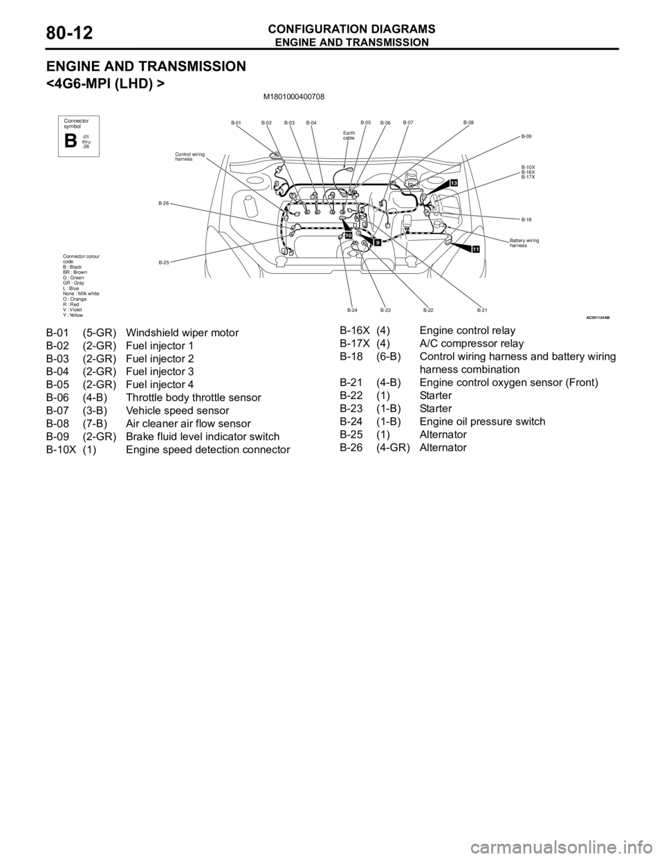
<4G6-MPI (LHD) >
M1801000400708
AC301134
B-02
B-03B-04
B-25 B-26Control wiring
harnessB-01
Connector colour
code
B : Black
BR : Brown
G : Green
GR : Gray
L : Blue
None : Milk white
O : Orange
R : Red
V : Violet
Y : YellowConnector
symbol
-01
thru
-26B
AB
910
11
13
B-06B-07
B-09
B-10X
B-16X
B-17X
B-18
Battery wiring
harness
B-21 B-22
B-23B-05B-08
B-24
Earth
cable
B-01 (5-GR) Windshield wiper motor
B-02 (2-GR) Fuel injector 1
B-03 (2-GR) Fuel injector 2
B-04 (2-GR) Fuel injector 3
B-05 (2-GR) Fuel injector 4
B-06 (4-B) Throttle body throttle sensor
B-07 (3-B) Vehicle speed sensor
B-08 (7-B) Air cleaner air flow sensor
B-09 (2-GR) Brake fluid level indicator switch
B-10X (1) Engine speed detection connectorB-16X (4) Engine control relay
B-17X (4) A/C compressor relay
B-18 (6-B) Control wiring harness and battery wiring
harness combination
B-21 (4-B) Engine control oxygen sensor (Front)
B-22 (1) Starter
B-23 (1-B) Starter
B-24 (1-B) Engine oil pressure switch
B-25 (1) Alternator
B-26 (4-GR) Alternator
Page 619 of 788
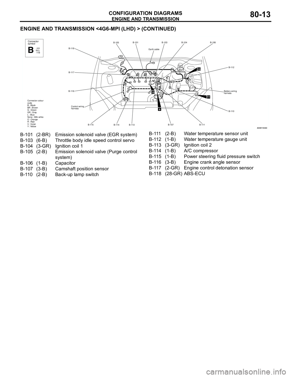
ENGINE AND TRANSMISSION
CONFIGURATION DIAGRAMS80-13
ENGINE AND TRANSMISSION <4G6-MPI (LHD) > (CONTINUED)
AC301134
B-118B-101
B-114 B-115 B-116B-117
Control wiring
harness Connector colour
code
B : Black
BR : Brown
G : Green
GR : Gray
L : Blue
None : Milk white
O : Orange
R : Red
V : Violet
Y : Yellow
B-113
B-105Connector
symbol
-101
thru
-118B
AC
9
10
11
13
B-103B-104B-106
B-112
B-110 Battery wiring
harness
B-111
B-107
Earth cable
B-101 (2-BR) Emission solenoid valve (EGR system)
B-103 (6-B) Throttle body idle speed control servo
B-104 (3-GR) Ignition coil 1
B-105 (2-B) Emission solenoid valve (Purge control
system)
B-106 (1-B) Capacitor
B-107 (3-B) Camshaft position sensor
B-110 (2-B) Back-up lamp switch B-111 (2-B) Water temperature sensor unit
B-112 (1-B) Water temperature gauge unit
B-113 (3-GR) Ignition coil 2
B-114 (1-B) A/C compressor
B-115 (1-B) Power steering fluid pressure switch
B-116 (3-B) Engine crank angle sensor
B-117 (2-GR) Engine control detonation sensor
B-118 (28-GR) ABS-ECU