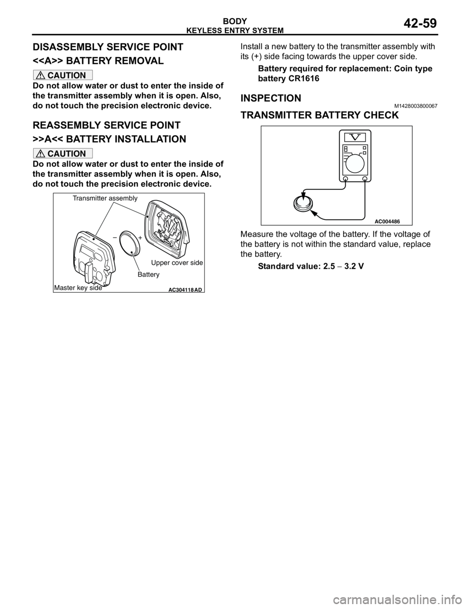
battery replacement MITSUBISHI LANCER 2005 Workshop Manual
[x] Cancel search | Manufacturer: MITSUBISHI, Model Year: 2005, Model line: LANCER, Model: MITSUBISHI LANCER 2005Pages: 788, PDF Size: 45.98 MB
Page 337 of 788

Page 456 of 788

HEADLAMP
CHASSIS ELECTRICAL54A-68
BULB REPLACEMENTM1542001300658
Headlamp Bulb
CAUTION
Do not touch the surface of the bulb with hands
or dirty gloves as the bulb may pop after a short
time. If the surface does become dirty, clean it
with alcohol or thinner, and let it dry thoroughly
before installing.
1. Disconnect the battery.
2. Disconnect the connector.
3. Remove the socket cover.
4. Remove bulb mounting spring to pull out bulb.
5. After bulb is replaced, properly reconnect
connector.
Position Lamp Bulb
CAUTION
Do not touch the bulb surface bare-handed or
with dirty gloves. If dirt is attached on surface of
the bulb, immediately use alcohol or thinner to
remove dirt, and install the bulb after well dried.
1.
Disconnect the connector.
2. Screw out position lamp socket to pull out
position lamp bulb.
Front Turn-Signal Lamp Bulb
CAUTION
Do not touch the bulb surface bare-handed or
with dirty gloves. If dirt is attached on surface of
the bulb, immediately use alcohol or thinner to
remove dirt, and install the bulb after well dried.
1.
Disconnect the connector.
2. Screw out front turn-signal lamp socket to pull out
front turn-signal lamp bulb.
AC300667AC300667
Headlamp bulb
AB
Spring
AC300668
Position lamp
AB
AC300669
Front turn signal lamp
AB
Page 560 of 788

ON-VEHICLE SERVICE
HEATER, AIR CONDITIONER AND VENTILATION55-76
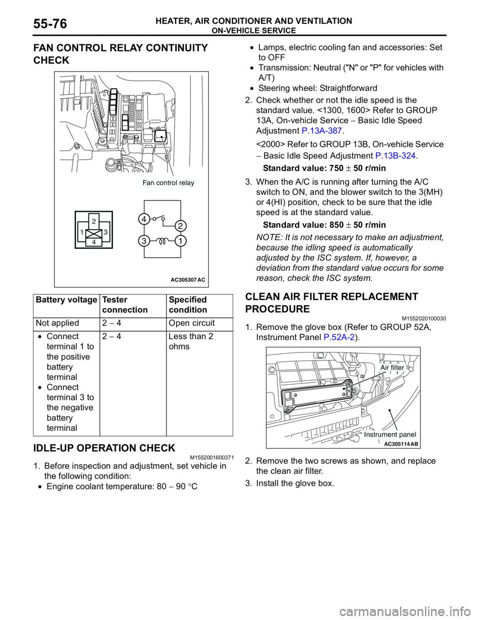
FAN CONTROL RELAY CONTINUITY
CHECK
IDLE-UP OPERATION CHECK
M1552001600371
1. Before inspection and adjustment, set vehicle in
the following condition:
•Engine coolant temperature: 80 − 90 °C•Lamps, electric cooling fan and accessories: Set
to OFF
•Transmission: Neutral ("N" or "P" for vehicles with
A/T)
•Steering wheel: Straightforward
2. Check whether or not the idle speed is the
standard value. <1300, 1600> Refer to GROUP
13A, On-vehicle Service − Basic Idle Speed
Adjustment P.13A-387.
<2000> Refer to GROUP 13B, On-vehicle Service
− Basic Idle Speed Adjustment P.13B-324.
Standard value: 750 ± 50 r/min
3. When the A/C is running after turning the A/C
switch to ON, and the blower switch to the 3(MH)
or 4(HI) position, check to be sure that the idle
speed is at the standard value.
Standard value: 850 ± 50 r/min
NOTE: It is not necessary to make an adjustment,
because the idling speed is automatically
adjusted by the ISC system. If, however, a
deviation from the standard value occurs for some
reason, check the ISC system.
CLEAN AIR FILTER REPLACEMENT
PROCEDURE
M1552020100030
1. Remove the glove box (Refer to GROUP 52A,
Instrument Panel P.52A-2).
2. Remove the two screws as shown, and replace
the clean air filter.
3. Install the glove box. Battery voltage Tester
connectionSpecified
condition
Not applied 2 − 4 Open circuit
•Connect
terminal 1 to
the positive
battery
terminal
•Connect
terminal 3 to
the negative
battery
terminal2 − 4 Less than 2
ohms
AC305307
Fan control relay
13
4 2
3 4
1 2
AC
AC305114AB
Air filter
Instrument panel