ect MITSUBISHI LANCER 2005 Workshop Manual
[x] Cancel search | Manufacturer: MITSUBISHI, Model Year: 2005, Model line: LANCER, Model: MITSUBISHI LANCER 2005Pages: 788, PDF Size: 45.98 MB
Page 355 of 788
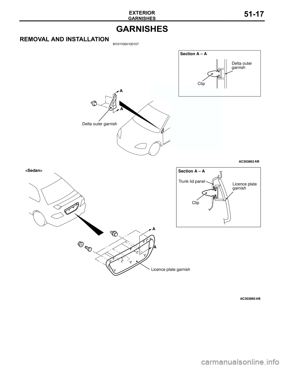
GARNISHES
EXTERIOR51-17
GARNISHES
REMOVAL AND INSTALLATIONM1511004100107
AC303863
Clip
Delta outer garnishSection A – A
AB
Delta outer
garnish
A A
AC303860
A A
Clip Trunk lid panel
Licence plate
garnish Section A – A
AB
Licence plate garnish
Page 356 of 788
REAR SPOILER
EXTERIOR51-18
REAR SPOILER
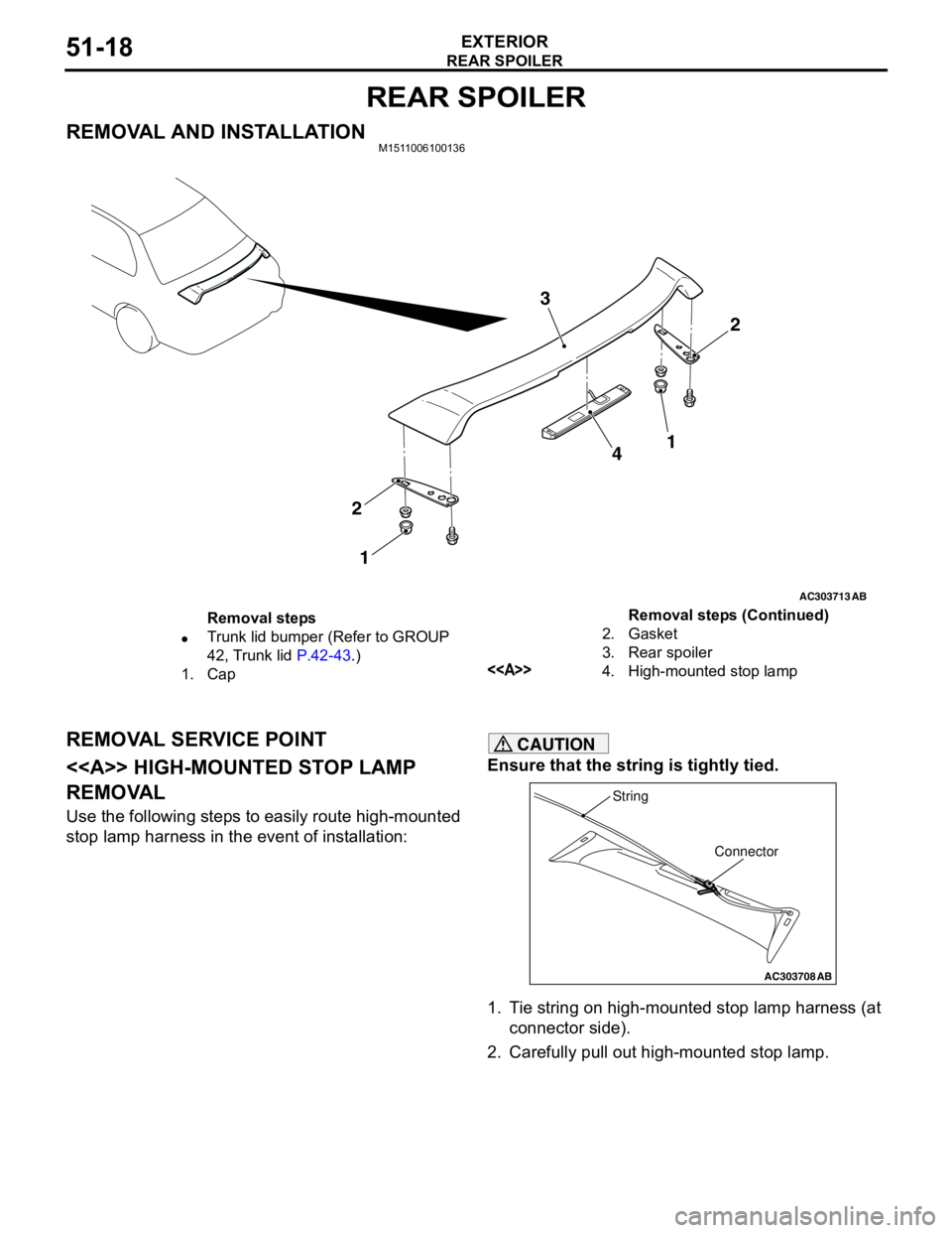
REMOVAL AND INSTALLATIONM1511006100136
REMOVAL SERVICE POINT
<> HIGH-MOUNTED STOP LAMP
REMOVAL
Use the following steps to easily route high-mounted
stop lamp harness in the event of installation:
CAUTION
Ensure that the string is tightly tied.
1. Tie string on high-mounted stop lamp harness (at
connector side).
2. Carefully pull out high-mounted stop lamp.
AC303713
2 3
4
2
1
AB
1
Removal steps
•Trunk lid bumper (Refer to GROUP
42, Trunk lid P.42-43.)
1. Cap2. Gasket
3. Rear spoiler
<>4. High-mounted stop lampRemoval steps (Continued)
AC303708
Connector String
AB
Page 357 of 788
TAILGATE SPOILER
EXTERIOR51-19
TAILGATE SPOILER
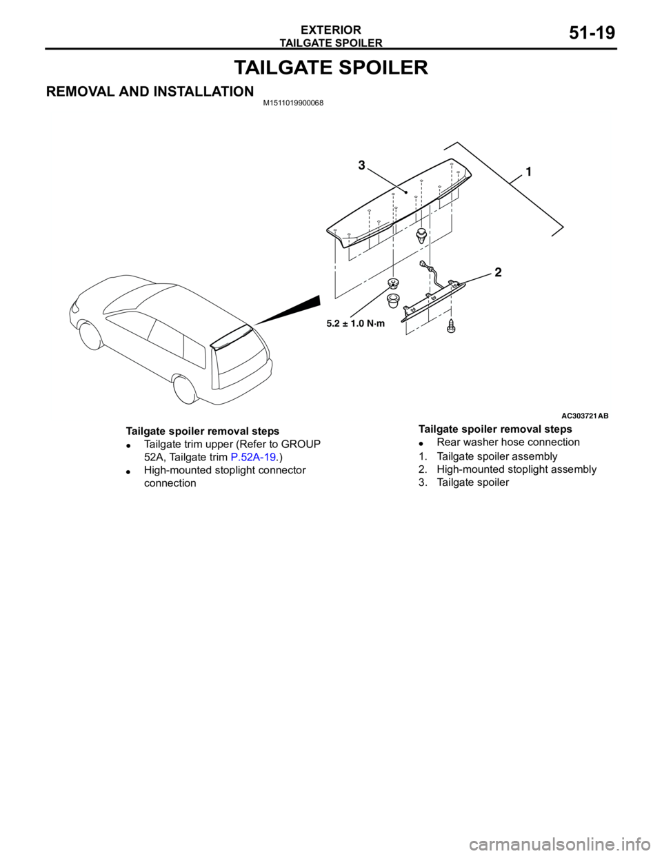
REMOVAL AND INSTALLATIONM1511019900068
AC303721
1
2 3
AB
5.2 ± 1.0 N·m
Tailgate spoiler removal steps
•Tailgate trim upper (Refer to GROUP
52A, Tailgate trim P.52A-19.)
•High-mounted stoplight connector
connection•Rear washer hose connection
1. Tailgate spoiler assembly
2. High-mounted stoplight assembly
3. Tailgate spoiler Tailgate spoiler removal steps
Page 358 of 788
ROOF RAIL
EXTERIOR51-20
ROOF RAIL
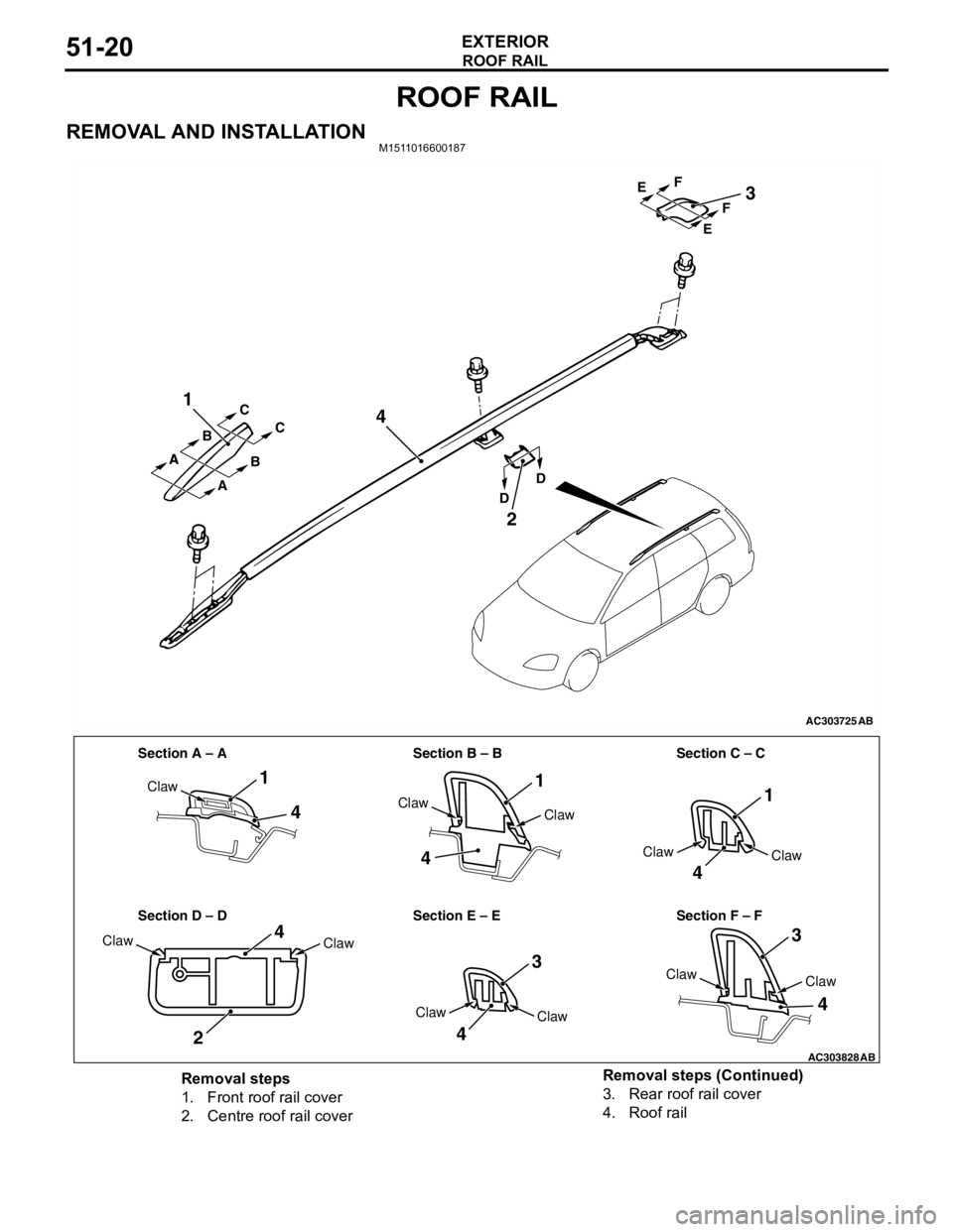
REMOVAL AND INSTALLATIONM1511016600187
AC303725
1
4
2
3
AB
A A
A BC
C
B
DDEF EF
AC303828
Section A – A Section B – B Section C – C
Section D – D Section E – E Section F – F
1
4
4
11
4
3
3
4
4
2
4
Claw
Claw
Claw
Claw
Claw
Claw
ClawClaw
Claw
Claw
Claw
AB
Removal steps
1. Front roof rail cover
2. Centre roof rail cover3. Rear roof rail cover
4. Roof rail Removal steps (Continued)
Page 360 of 788
WINDSHIELD WIPER AND WASHER
EXTERIOR51-22
SERVICE SPECIFICATIONM1511000300325
TROUBLESHOOTINGM1511000700323
The windshield wiper and washer are controlled by
the Smart Wiring System (SWS). For
troubleshooting, refer to GROUP 54B,
Troubleshooting P.54B-17 or GROUP 54C,
Troubleshooting P.54C-4.
NOTE: Even when the ETACS-ECU has failed, the
windshield wiper can work at low speed as fail-safe
mode. (Normally, the windshield wiper operates
when the ignition switch is at the "ACC" position. But,
if it enters the fail-safe mode, the wiper can operate
only when the ignition switch is at the "ON" position.)
ON-VEHICLE SERVICEM1511000800461
WINDSHIELD INTERMITTENT WIPER
INSPECTION
1. If the windshield intermittent wiper interval
adjusting knob is operated, the wiper interval
should change.
2. Holding the windshield intermittent wiper interval
adjusting knob, input the simulated vehicle speed
with MUT-II MB991502 and check that the wiper
interval changes as the vehicle speed changes.
3. If not, carry out the troubleshooting (Refer to
GROUP 54B, Troubleshooting P.54B-17 or
GROUP 54C, Troubleshooting P.54C-4). ItemStandard value
Windshield wiper blade park position mm 34 ± 5
Page 361 of 788
WINDSHIELD WIPER AND WASHER
EXTERIOR51-23
WINDSHIELD WIPER AND WASHER
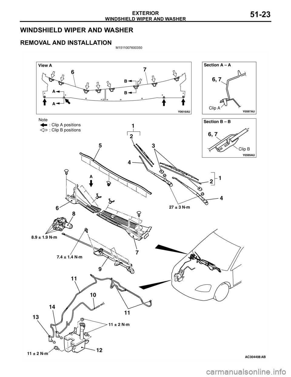
REMOVAL AND INSTALLATIONM1511007600350
Y0597AU
Y0616AU
Y0599AU
AC304408AB
Section B – B Section A – A
View A
A A
AB
B
Clip A
Clip B
6, 7
6, 7
67
3
2 5
6
7 8
9
10 11
11
12 1314
27 ± 3 N·m
8.9 ± 1.9 N·m
11 ± 2 N·m
Note
: Clip A positions
: Clip B positions
11 ± 2 N·m
7.4 ± 1.4 N·m
2
1
1 4
4
Page 362 of 788
WINDSHIELD WIPER AND WASHER
EXTERIOR51-24
NOTE: For removal and installation of the wiper and
washer switch, refer to GROUP 54A, Column switch
P.54A-87.
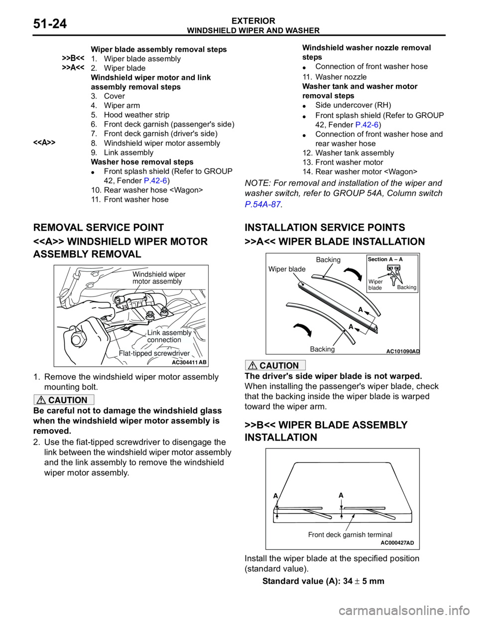
REMOVAL SERVICE POINT
<> WINDSHIELD WIPER MOTOR
ASSEMBLY REMOVAL
1. Remove the windshield wiper motor assembly
mounting bolt.
CAUTION
Be careful not to damage the windshield glass
when the windshield wiper motor assembly is
removed.
2. Use the fiat-tipped screwdriver to disengage the
link between the windshield wiper motor assembly
and the link assembly to remove the windshield
wiper motor assembly.
INSTALLATION SERVICE POINTS
>>A<< WIPER BLADE INSTALLATION
CAUTION
The driver's side wiper blade is not warped.
When installing the passenger's wiper blade, check
that the backing inside the wiper blade is warped
toward the wiper arm.
>>B<< WIPER BLADE ASSEMBLY
INSTALLATION
Install the wiper blade at the specified position
(standard value).
Standard value (A): 34 ± 5 mm
Wiper blade assembly removal steps
>>B<<1. Wiper blade assembly
>>A<<2. Wiper blade
Windshield wiper motor and link
assembly removal steps
3. Cover
4. Wiper arm
5. Hood weather strip
6. Front deck garnish (passenger's side)
7. Front deck garnish (driver's side)
<>8. Windshield wiper motor assembly
9. Link assembly
Washer hose removal steps
•Front splash shield (Refer to GROUP
42, Fender P.42-6)
10. Rear washer hose
11. Front washer hoseWindshield washer nozzle removal
steps
•Connection of front washer hose
11. Washer nozzle
Washer tank and washer motor
removal steps
•Side undercover (RH)
•Front splash shield (Refer to GROUP
42, Fender P.42-6)
•Connection of front washer hose and
rear washer hose
12. Washer tank assembly
13. Front washer motor
14. Rear washer motor
AC304411AB
Windshield wiper
motor assembly
Link assembly
connection
Flat-tipped screwdriverAC101090AD
Wiper bladeBacking
BackingA
A
Section A – A
Wiper
bladeBacking
AC000427
A
A
Front deck garnish terminalAD
Page 363 of 788
WINDSHIELD WIPER AND WASHER
EXTERIOR51-25
INSPECTIONM1511007700313
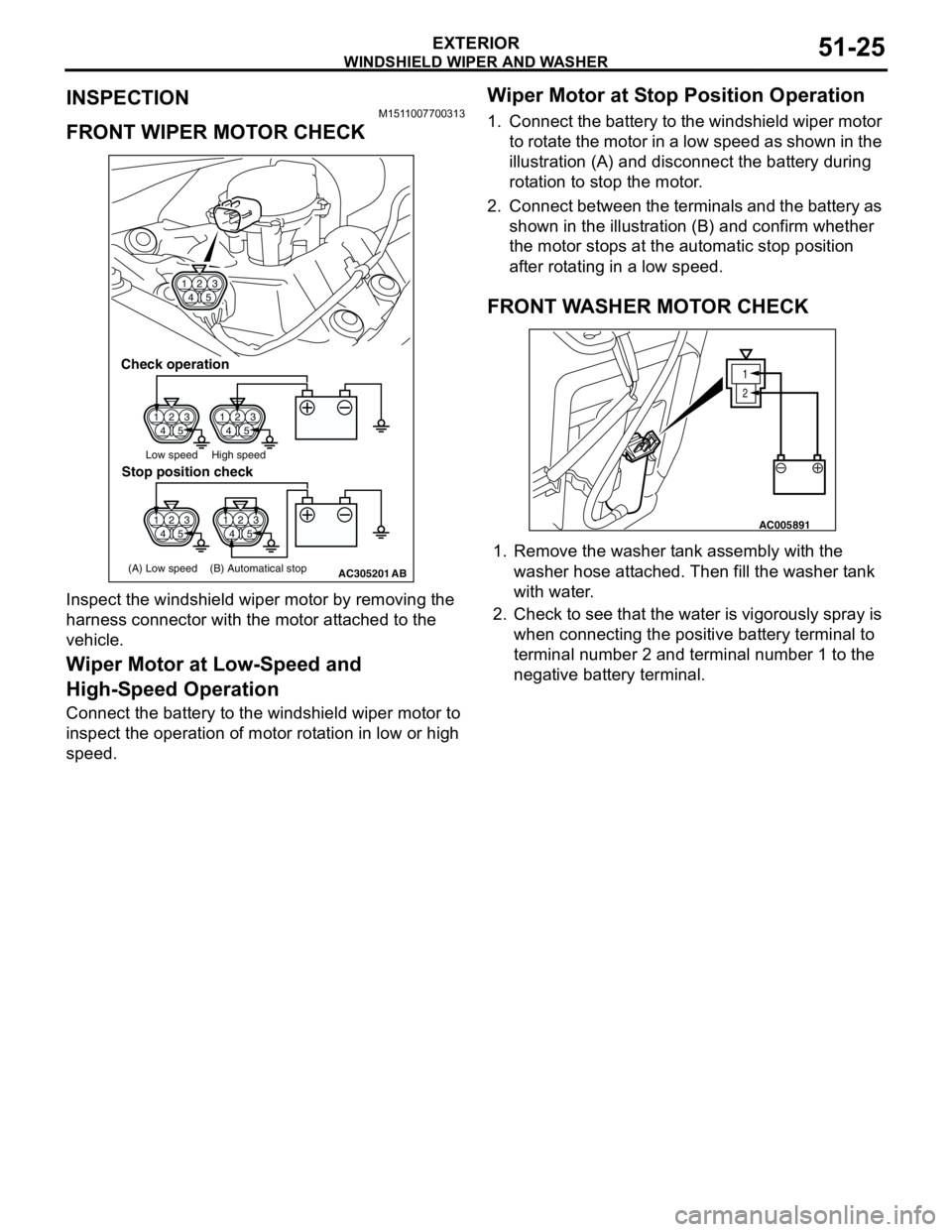
FRONT WIPER MOTOR CHECK
Inspect the windshield wiper motor by removing the
harness connector with the motor attached to the
vehicle.
Wiper Motor at Low-Speed and
High-Speed Operation
Connect the battery to the windshield wiper motor to
inspect the operation of motor rotation in low or high
speed.
Wiper Motor at Stop Position Operation
1. Connect the battery to the windshield wiper motor
to rotate the motor in a low speed as shown in the
illustration (A) and disconnect the battery during
rotation to stop the motor.
2. Connect between the terminals and the battery as
shown in the illustration (B) and confirm whether
the motor stops at the automatic stop position
after rotating in a low speed.
FRONT WASHER MOTOR CHECK
1. Remove the washer tank assembly with the
washer hose attached. Then fill the washer tank
with water.
2. Check to see that the water is vigorously spray is
when connecting the positive battery terminal to
terminal number 2 and terminal number 1 to the
negative battery terminal.
1
423
5
1
423
51
423
5
1
423
5
AC305201
1
423
5
Check operation
Low speed High speed
(A) Low speed (B) Automatical stop
Stop position check
AB
1
2
AC005891
Page 364 of 788
WINDSHIELD WIPER AND WASHER
EXTERIOR51-26
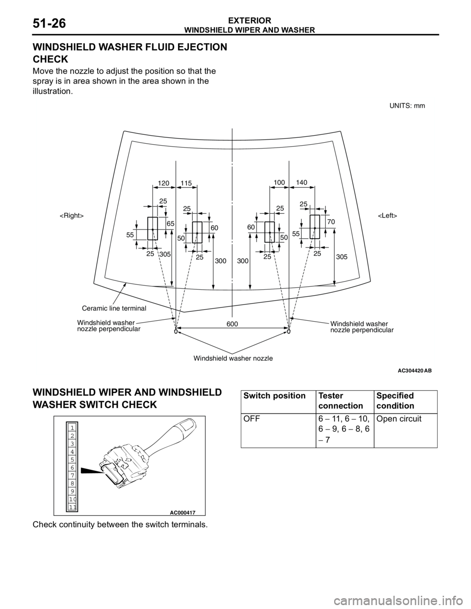
WINDSHIELD WASHER FLUID EJECTION
CHECK
Move the nozzle to adjust the position so that the
spray is in area shown in the area shown in the
illustration.
WINDSHIELD WIPER AND WINDSHIELD
WASHER SWITCH CHECK
Check continuity between the switch terminals.
AC304420
305 70 25
55140 100
120 115
305
300
600 300252525
25
25
25 25
55
6560
50
60
50
AB
Windshield washer
nozzle perpendicular Windshield washer
nozzle perpendicular
Windshield washer nozzle
Ceramic line terminal
UNITS: mm
1
6
8
11 109 7
5 4
3
2
AC000417
Switch position Tester
connectionSpecified
condition
OFF 6 − 11 , 6 − 10,
6 − 9, 6 − 8, 6
− 7Open circuit
Page 365 of 788
WINDSHIELD WIPER AND WASHER
EXTERIOR51-27
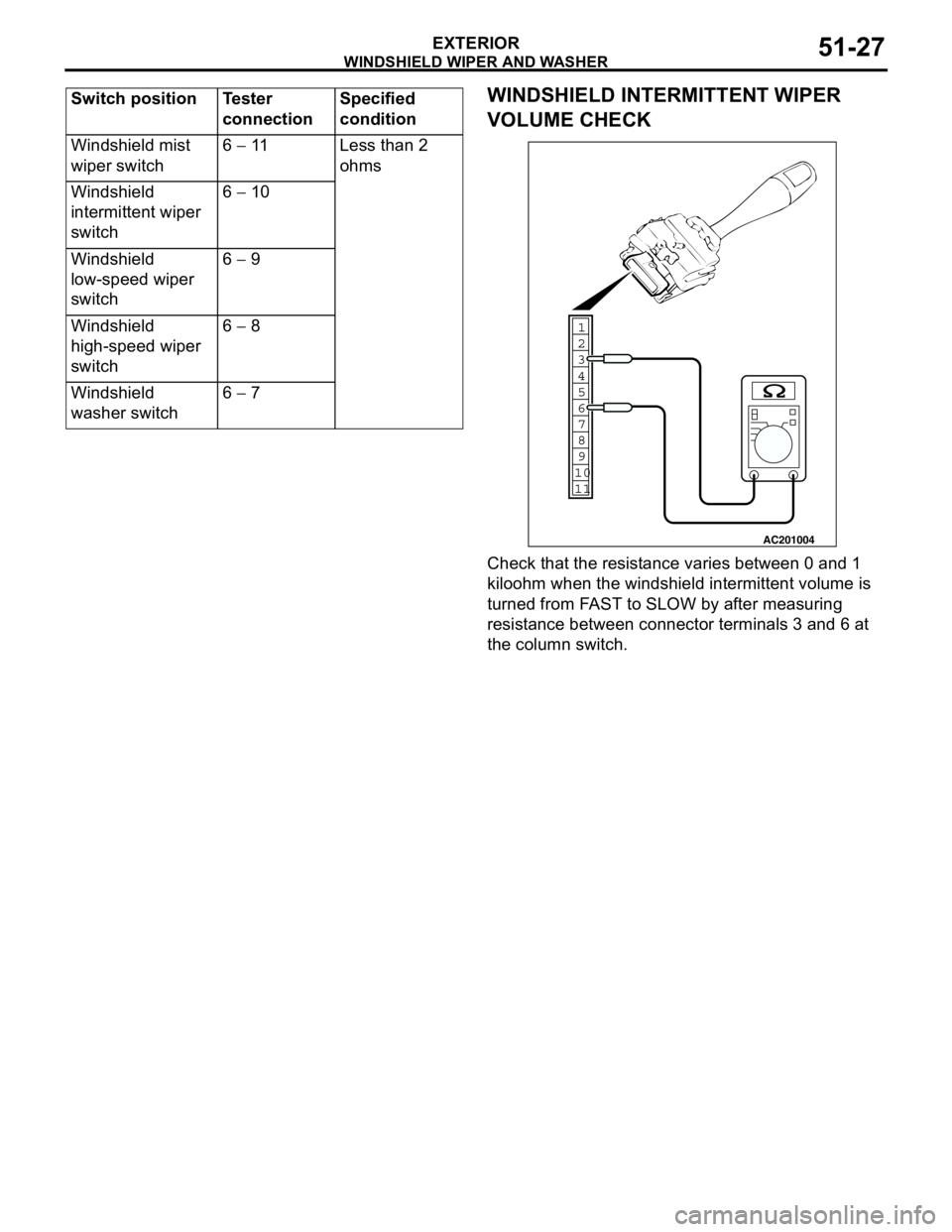
WINDSHIELD INTERMITTENT WIPER
VOLUME CHECK
Check that the resistance varies between 0 and 1
kiloohm when the windshield intermittent volume is
turned from FAST to SLOW by after measuring
resistance between connector terminals 3 and 6 at
the column switch. Windshield mist
wiper switch6 − 11 Less than 2
ohms
Windshield
intermittent wiper
switch6 − 10
Windshield
low-speed wiper
switch6 − 9
Windshield
high-speed wiper
switch6 − 8
Windshield
washer switch6 − 7 Switch position Tester
connectionSpecified
condition
1
6
8
11 109 7
5 4 3
2
AC201004