washer fluid MITSUBISHI LANCER 2005 Workshop Manual
[x] Cancel search | Manufacturer: MITSUBISHI, Model Year: 2005, Model line: LANCER, Model: MITSUBISHI LANCER 2005Pages: 788, PDF Size: 45.98 MB
Page 146 of 788
DRIVE SHAFT ASSEMBLY
FRONT AXLE26-14
DRIVE SHAFT ASSEMBLY
REMOVAL AND INSTALLATIONM1261003500399
CAUTION
•Do not strike the ABS rotors installed to the BJ outer race of drive shaft against other parts when
removing or installing the drive shaft. Otherwise the ABS rotors will be damaged.
•Be careful not to strike the pole piece at the tip of the front ABS sensor with tools during servicing
work.
Pre-installation Operation
•Transmission Fluid Draining (Refer to GROUP
22A, On-vehicle Service − Transmission Oil
Replacement P.22A-8).
•Front Exhaust Pipe Removal (Refer to GROUP
15, Exhaust Pipe and Muffler P.15-11).Post-installation Operation
•Front Exhaust Pipe Installation (Refer to
GROUP 15, Exhaust Pipe and Muffler
P.15-11).
•Check the Ball Joint Dust Cover for cracks or
damage by pushing it with your finger.
•Transmission Fluid Filling (Refer to GROUP
22A, On-vehicle Service − Transmission Oil
Replacement P.22A-8).
AC303689AB
9
N
N
NN
10 7
4
3
2
1
25 ± 5 N·m
245 ± 29 N·m
108 ± 10 N·m
8
5 6
1112
7
7
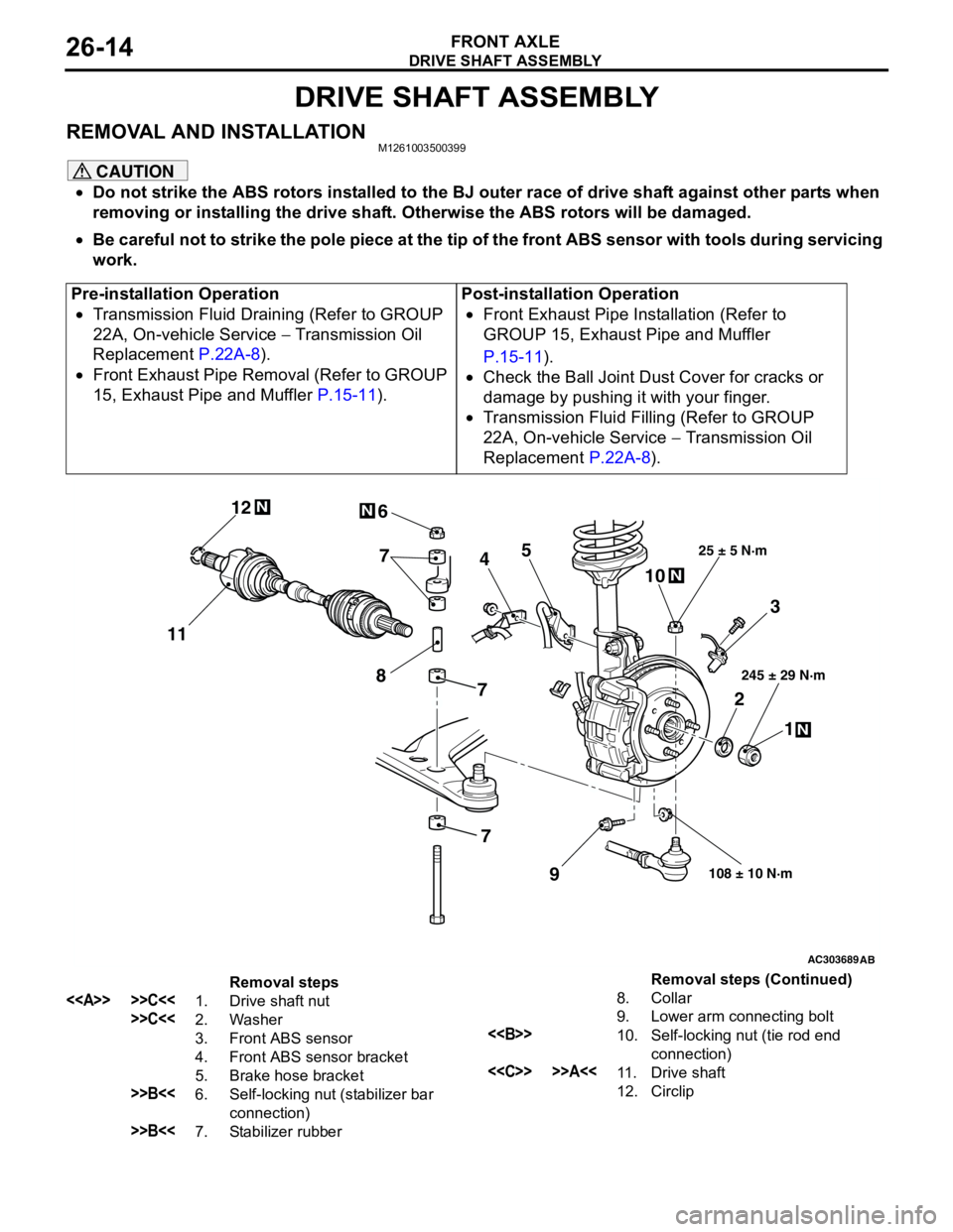
Removal steps
<> >>C<<1. Drive shaft nut
>>C<<2. Washer
3. Front ABS sensor
4. Front ABS sensor bracket
5. Brake hose bracket
>>B<<6. Self-locking nut (stabilizer bar
connection)
>>B<<7. Stabilizer rubber8. Collar
9. Lower arm connecting bolt
<>10. Self-locking nut (tie rod end
connection)
<
12. CirclipRemoval steps (Continued)
Page 364 of 788
WINDSHIELD WIPER AND WASHER
EXTERIOR51-26
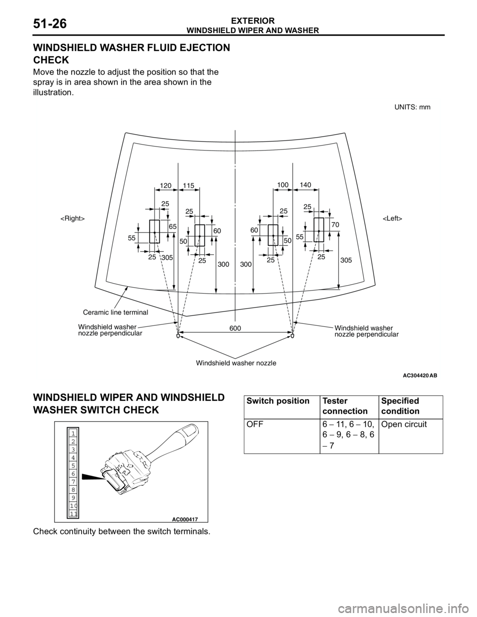
WINDSHIELD WASHER FLUID EJECTION
CHECK
Move the nozzle to adjust the position so that the
spray is in area shown in the area shown in the
illustration.
WINDSHIELD WIPER AND WINDSHIELD
WASHER SWITCH CHECK
Check continuity between the switch terminals.
AC304420
305 70 25
55140 100
120 115
305
300
600 300252525
25
25
25 25
55
6560
50
60
50
AB
Windshield washer
nozzle perpendicular Windshield washer
nozzle perpendicular
Windshield washer nozzle
Ceramic line terminal
UNITS: mm
1
6
8
11 109 7
5 4
3
2
AC000417
Switch position Tester
connectionSpecified
condition
OFF 6 − 11 , 6 − 10,
6 − 9, 6 − 8, 6
− 7Open circuit
Page 369 of 788
REAR WIPER AND WASHER
EXTERIOR51-31
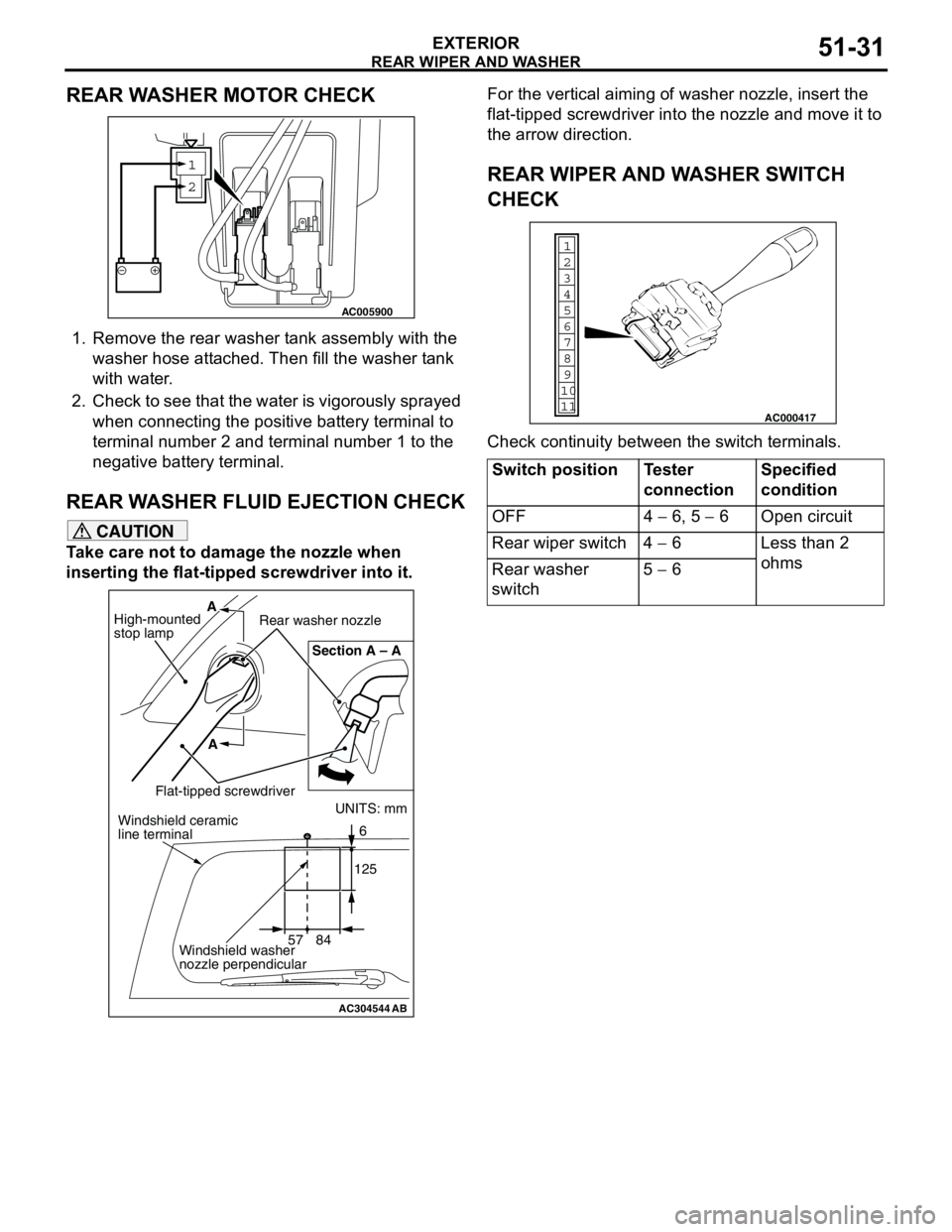
REAR WASHER MOTOR CHECK
1. Remove the rear washer tank assembly with the
washer hose attached. Then fill the washer tank
with water.
2. Check to see that the water is vigorously sprayed
when connecting the positive battery terminal to
terminal number 2 and terminal number 1 to the
negative battery terminal.
REAR WASHER FLUID EJECTION CHECK
CAUTION
Take care not to damage the nozzle when
inserting the flat-tipped screwdriver into it.For the vertical aiming of washer nozzle, insert the
flat-tipped screwdriver into the nozzle and move it to
the arrow direction.
REAR WIPER AND WASHER SWITCH
CHECK
Check continuity between the switch terminals.
1
2
AC005900
AC304544AB
UNITS: mm
57 841256 Section A – A
A A
High-mounted
stop lampRear washer nozzle
Flat-tipped screwdriverWindshield ceramic
line terminal
Windshield washer
nozzle perpendicular
Switch position Tester
connectionSpecified
condition
OFF 4 − 6, 5 − 6 Open circuit
Rear wiper switch 4 − 6 Less than 2
ohms
Rear washer
switch5 − 6
1
6
8
11 109 7
5 4
3
2
AC000417
Page 370 of 788
HEADLAMP WASHER
EXTERIOR51-32
HEADLAMP WASHER
TROUBLESHOOTINGM1511000700356
The headlamp washer is controlled by the Smart
Wiring System (SWS). For troubleshooting, refer to
GROUP 54B, Troubleshooting P.54B-17 or GROUP
54C, Troubleshooting P.54C-4.
HEADLAMP WASHER
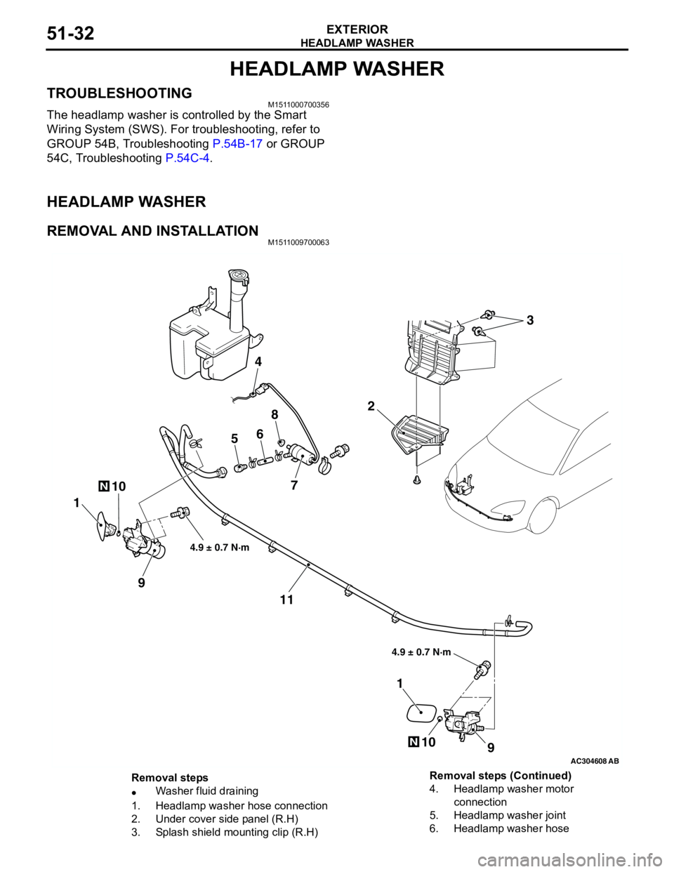
REMOVAL AND INSTALLATIONM1511009700063
AC304608AB
10N
2
4
56
8
7
1
9
11
9
1
10N
4.9 ± 0.7 N·m 4.9 ± 0.7 N·m
3
Removal steps
•Washer fluid draining
1. Headlamp washer hose connection
2. Under cover side panel (R.H)
3. Splash shield mounting clip (R.H)4. Headlamp washer motor
connection
5. Headlamp washer joint
6. Headlamp washer hose Removal steps (Continued)
Page 729 of 788
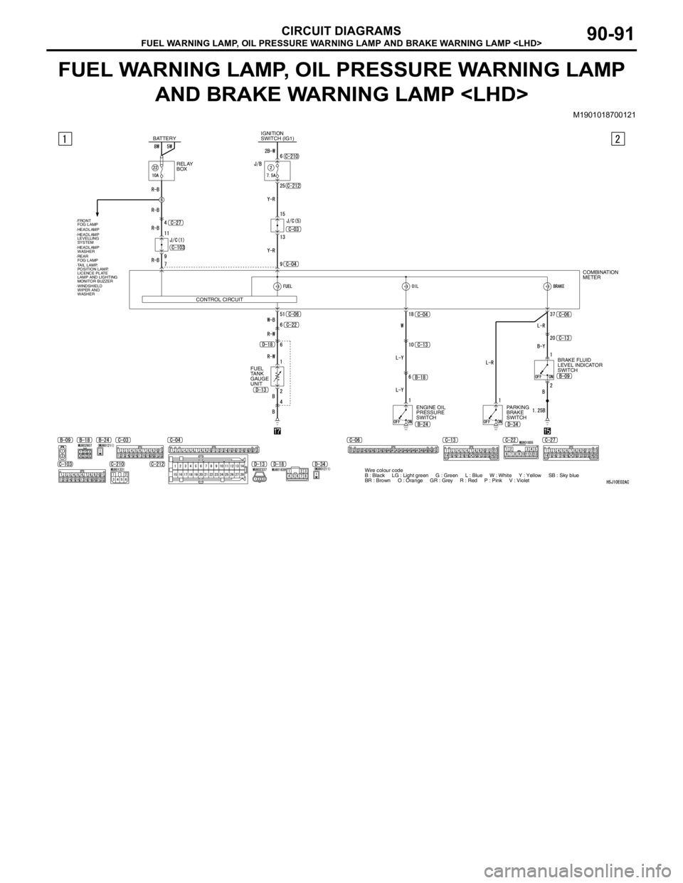
FUEL WARNING LAMP, OIL PRESSURE WARNING LAMP AND BRAKE WARNING LAMP
CIRCUIT DIAGRAMS90-91
FUEL WARNING LAMP, OIL PRESSURE WARNING LAMP
AND BRAKE WARNING LAMP
M1901018700121
BATTERYIGNITION
SWITCH (IG1)
RELAY
BOX
CONTROL CIRCUIT
·FRONT
FOG LAMP
·TAIL LAMP,
POSITION LAMP,
LICENCE PLATE
LAMP AND LIGHTING
MONITOR BUZZER ·HEADLAMP
·WINDSHIELD
WIPER AND
WASHER ·REAR
FOG LAMP ·HEADLAMP
LEVELLING
SYSTEM
FUEL
TANK
GAUGE
UNIT
·HEADLAMP
WASHER
COMBINATION
METER
BRAKE FLUID
LEVEL INDICATOR
SWITCH
ENGINE OIL
PRESSURE
SWITCHPARKING
BRAKE
SWITCH
Wire colour code
B : Black LG : Light green G : Green L : Blue W : White Y : Yellow SB : Sky blue
BR : Brown O : Orange GR : Grey R : Red P : Pink V : Violet
Page 730 of 788
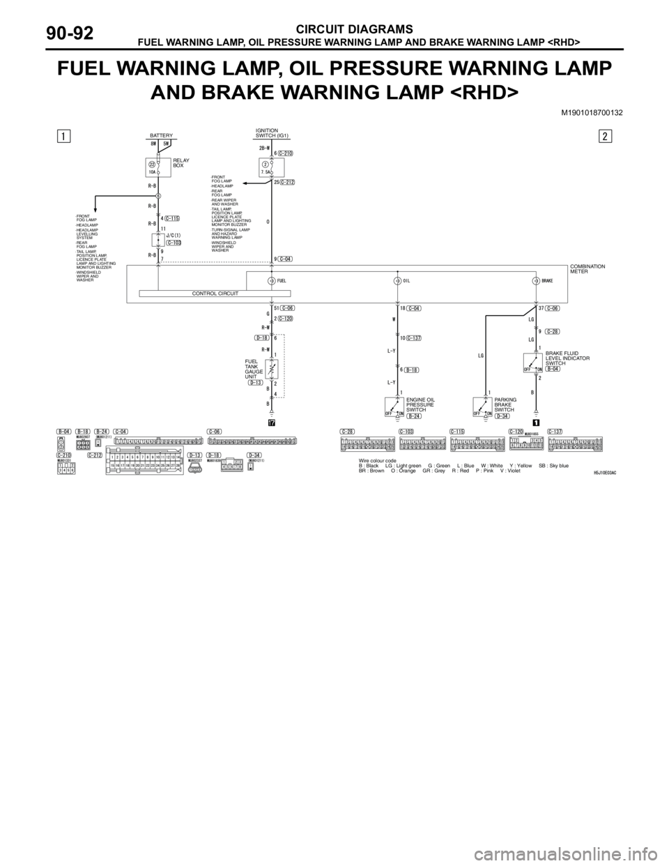
FUEL WARNING LAMP, OIL PRESSURE WARNING LAMP AND BRAKE WARNING LAMP
CIRCUIT DIAGRAMS90-92
FUEL WARNING LAMP, OIL PRESSURE WARNING LAMP
AND BRAKE WARNING LAMP
M1901018700132
Wire colour code
B : Black LG : Light green G : Green L : Blue W : White Y : Yellow SB : Sky blue
BR : Brown O : Orange GR : Grey R : Red P : Pink V : Violet COMBINATION
METER
BRAKE FLUID
LEVEL INDICATOR
SWITCH
ENGINE OIL
PRESSURE
SWITCHPARKING
BRAKE
SWITCH RELAY
BOX BATTERYIGNITION
SWITCH (IG1)
CONTROL CIRCUIT
·FRONT
FOG LAMP
·TAIL LAMP,
POSITION LAMP,
LICENCE PLATE
LAMP AND LIGHTING
MONITOR BUZZER ·HEADLAMP
·WINDSHIELD
WIPER AND
WASHER ·REAR
FOG LAMP
·TURN-SIGNAL LAMP
AND HAZARD
WARNING LAMP
FUEL
TANK
GAUGE
UNIT
·REAR WIPER
AND WASHER
·FRONT
FOG LAMP
·TAIL LAMP,
POSITION LAMP,
LICENCE PLATE
LAMP AND LIGHTING
MONITOR BUZZER ·HEADLAMP
·WINDSHIELD
WIPER AND
WASHER ·REAR
FOG LAMP ·HEADLAMP
LEVELLING
SYSTEM