lock MITSUBISHI LANCER 2005 Owner's Manual
[x] Cancel search | Manufacturer: MITSUBISHI, Model Year: 2005, Model line: LANCER, Model: MITSUBISHI LANCER 2005Pages: 788, PDF Size: 45.98 MB
Page 142 of 788
FRONT AXLE HUB ASSEMBLY
FRONT AXLE26-10
<
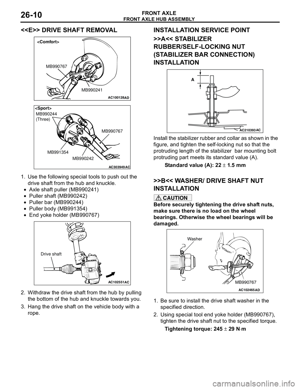
1. Use the following special tools to push out the
drive shaft from the hub and knuckle.
•Axle shaft puller (MB990241)
•Puller shaft (MB990242)
•Puller bar (MB990244)
•Puller body (MB991354)
•End yoke holder (MB990767)
2. Withdraw the drive shaft from the hub by pulling
the bottom of the hub and knuckle towards you.
3. Hang the drive shaft on the vehicle body with a
rope.
INSTALLATION SERVICE POINT
>>A<< STABILIZER
RUBBER/SELF-LOCKING NUT
(STABILIZER BAR CONNECTION)
INSTALLATION
Install the stabilizer rubber and collar as shown in the
figure, and tighten the self-locking nut so that the
protruding length of the stabilizer bar mounting bolt
protruding part meets its standard value (A).
Standard value (A): 22 ± 1.5 mm
>>B<< WASHER/ DRIVE SHAFT NUT
INSTALLATION
CAUTION
Before securely tightening the drive shaft nuts,
make sure there is no load on the wheel
bearings. Otherwise the wheel bearings will be
damaged.
1. Be sure to install the drive shaft washer in the
specified direction.
2. Using special tool end yoke holder (MB990767),
tighten the drive shaft nut to the specified torque.
Tightening torque: 245 ± 29 N⋅m
AC100128
MB990241 MB990767
AD
AC303949
MB990244
(Three)
MB990767
MB990242 MB991354
AC
AC102551
AC
Drive shaft
AC210393AC
A
AC102465AD
MB990767 Washer
Page 146 of 788
DRIVE SHAFT ASSEMBLY
FRONT AXLE26-14
DRIVE SHAFT ASSEMBLY
REMOVAL AND INSTALLATIONM1261003500399
CAUTION
•Do not strike the ABS rotors installed to the BJ outer race of drive shaft against other parts when
removing or installing the drive shaft. Otherwise the ABS rotors will be damaged.
•Be careful not to strike the pole piece at the tip of the front ABS sensor with tools during servicing
work.
Pre-installation Operation
•Transmission Fluid Draining (Refer to GROUP
22A, On-vehicle Service − Transmission Oil
Replacement P.22A-8).
•Front Exhaust Pipe Removal (Refer to GROUP
15, Exhaust Pipe and Muffler P.15-11).Post-installation Operation
•Front Exhaust Pipe Installation (Refer to
GROUP 15, Exhaust Pipe and Muffler
P.15-11).
•Check the Ball Joint Dust Cover for cracks or
damage by pushing it with your finger.
•Transmission Fluid Filling (Refer to GROUP
22A, On-vehicle Service − Transmission Oil
Replacement P.22A-8).
AC303689AB
9
N
N
NN
10 7
4
3
2
1
25 ± 5 N·m
245 ± 29 N·m
108 ± 10 N·m
8
5 6
1112
7
7
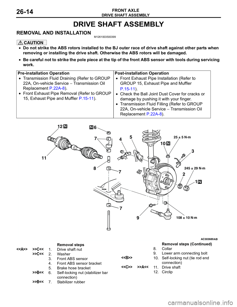
Removal steps
<> >>C<<1. Drive shaft nut
>>C<<2. Washer
3. Front ABS sensor
4. Front ABS sensor bracket
5. Brake hose bracket
>>B<<6. Self-locking nut (stabilizer bar
connection)
>>B<<7. Stabilizer rubber8. Collar
9. Lower arm connecting bolt
<>10. Self-locking nut (tie rod end
connection)
<
12. CirclipRemoval steps (Continued)
Page 147 of 788
Page 149 of 788
DRIVE SHAFT ASSEMBLY
FRONT AXLE26-17
INSTALLATION SERVICE POINTS
>>A<< DRIVE SHAFT INSTALLATION
CAUTION
When installing the drive shaft, be careful that
the spline part of the drive shaft does not
damage the oil seal.
>>B<< STABILIZER
RUBBER/SELF-LOCKING NUT
(STABILIZER BAR CONNECTION)
INSTALLATION
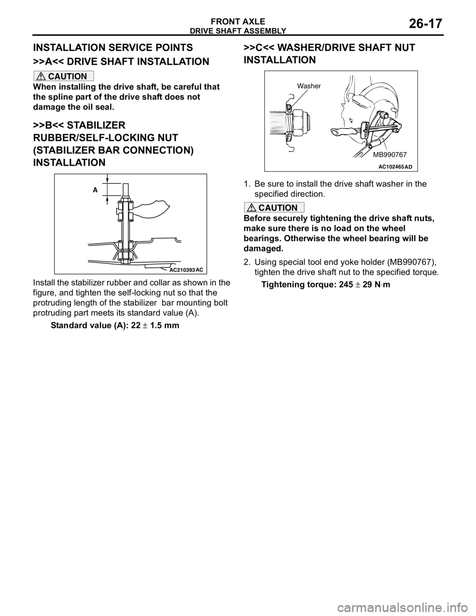
Install the stabilizer rubber and collar as shown in the
figure, and tighten the self-locking nut so that the
protruding length of the stabilizer bar mounting bolt
protruding part meets its standard value (A).
Standard value (A): 22 ± 1.5 mm
>>C<< WASHER/DRIVE SHAFT NUT
INSTALLATION
1. Be sure to install the drive shaft washer in the
specified direction.
CAUTION
Before securely tightening the drive shaft nuts,
make sure there is no load on the wheel
bearings. Otherwise the wheel bearing will be
damaged.
2. Using special tool end yoke holder (MB990767),
tighten the drive shaft nut to the specified torque.
Tightening torque: 245 ± 29 N⋅m
AC210393AC
A
AC102465AD
MB990767 Washer
Page 160 of 788
ON-VEHICLE SERVICE
REAR AXLE27-4
ON-VEHICLE SERVICE
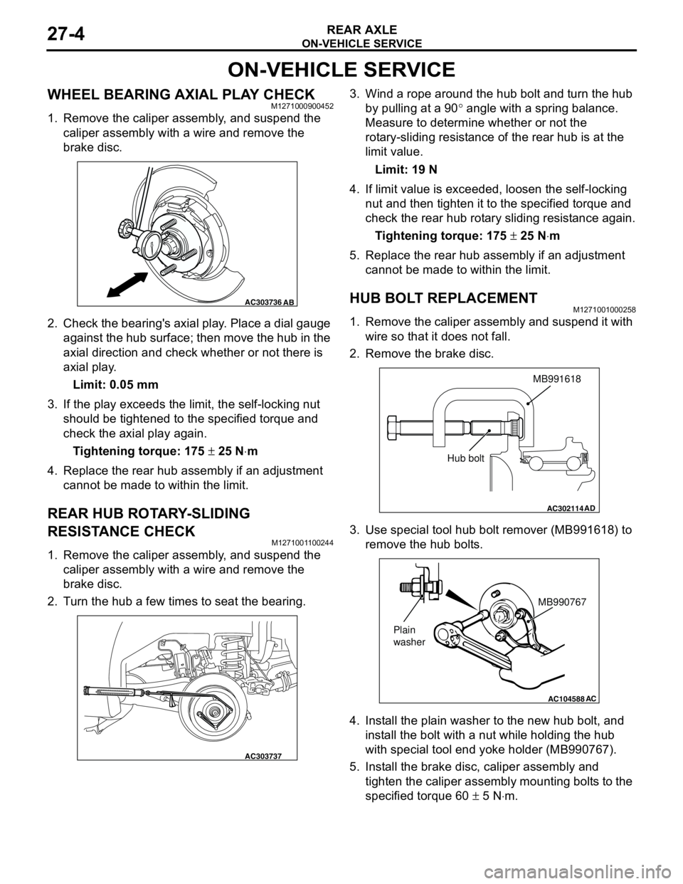
WHEEL BEARING AXIAL PLAY CHECKM1271000900452
1. Remove the caliper assembly, and suspend the
caliper assembly with a wire and remove the
brake disc.
2. Check the bearing's axial play. Place a dial gauge
against the hub surface; then move the hub in the
axial direction and check whether or not there is
axial play.
Limit: 0.05 mm
3. If the play exceeds the limit, the self-locking nut
should be tightened to the specified torque and
check the axial play again.
Tightening torque: 175 ± 25 N⋅m
4. Replace the rear hub assembly if an adjustment
cannot be made to within the limit.
REAR HUB ROTARY-SLIDING
RESISTANCE CHECK
M1271001100244
1. Remove the caliper assembly, and suspend the
caliper assembly with a wire and remove the
brake disc.
2. Turn the hub a few times to seat the bearing.3. Wind a rope around the hub bolt and turn the hub
by pulling at a 90° angle with a spring balance.
Measure to determine whether or not the
rotary-sliding resistance of the rear hub is at the
limit value.
Limit: 19 N
4. If limit value is exceeded, loosen the self-locking
nut and then tighten it to the specified torque and
check the rear hub rotary sliding resistance again.
Tightening torque: 175 ± 25 N⋅m
5. Replace the rear hub assembly if an adjustment
cannot be made to within the limit.
HUB BOLT REPLACEMENTM1271001000258
1. Remove the caliper assembly and suspend it with
wire so that it does not fall.
2. Remove the brake disc.
3. Use special tool hub bolt remover (MB991618) to
remove the hub bolts.
4. Install the plain washer to the new hub bolt, and
install the bolt with a nut while holding the hub
with special tool end yoke holder (MB990767).
5. Install the brake disc, caliper assembly and
tighten the caliper assembly mounting bolts to the
specified torque 60 ± 5 N⋅m.
AC303736AB
AC303737
AC302114
MB991618
AD
Hub bolt
AC104588
MB990767
Plain
washer
AC
Page 161 of 788
REAR AXLE HUB ASSEMBLY
REAR AXLE27-5
REAR AXLE HUB ASSEMBLY
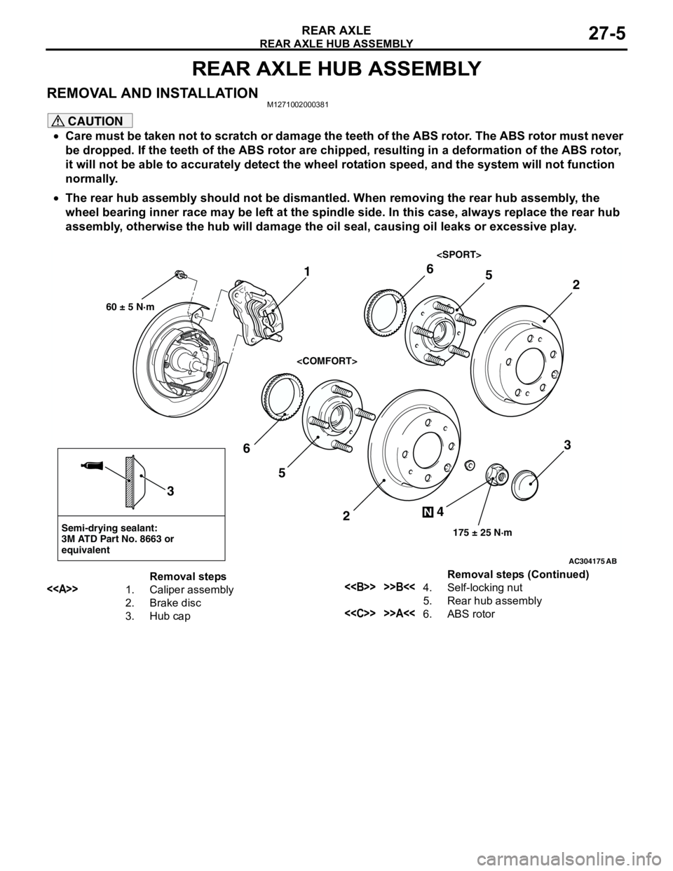
REMOVAL AND INSTALLATIONM1271002000381
CAUTION
•Care must be taken not to scratch or damage the teeth of the ABS rotor. The ABS rotor must never
be dropped. If the teeth of the ABS rotor are chipped, resulting in a deformation of the ABS rotor,
it will not be able to accurately detect the wheel rotation speed, and the system will not function
normally.
•The rear hub assembly should not be dismantled. When removing the rear hub assembly, the
wheel bearing inner race may be left at the spindle side. In this case, always replace the rear hub
assembly, otherwise the hub will damage the oil seal, causing oil leaks or excessive play.
AC304175
Semi-drying sealant:
3M ATD Part No. 8663 or
equivalent
2
3
5 6
4
N
175 ± 25 N·m
3
AB
1
60 ± 5 N·m
2
56
Removal steps
<>1. Caliper assembly
2. Brake disc
3. Hub cap<> >>B<<4. Self-locking nut
5. Rear hub assembly
<
Page 162 of 788
Page 174 of 788
ENGINE MOUNTING
POWER PLANT MOUNT32-4
ENGINE MOUNTING
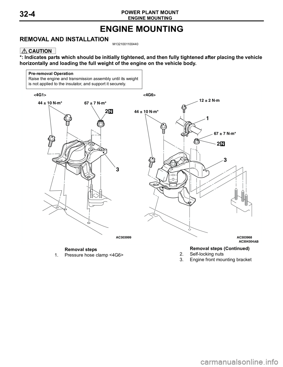
REMOVAL AND INSTALLATIONM1321001100440
CAUTION
*: Indicates parts which should be initially tightened, and then fully tightened after placing the vehicle
horizontally and loading the full weight of the engine on the vehicle body.
Pre-removal Operation
Raise the engine and transmission assembly until its weight
is not applied to the insulator, and support it securely.
AC303999AC303968AC304304
AB
<4G1> <4G6>
44 ± 10 N·m*
67 ± 7 N·m*
2N
3
44 ± 10 N·m*
67 ± 7 N·m*
2N
3
12 ± 2 N·m
1
Removal steps
1. Pressure hose clamp <4G6>2. Self-locking nuts
3. Engine front mounting bracketRemoval steps (Continued)
Page 178 of 788
CROSSMEMBER
POWER PLANT MOUNT32-8
INSTALLATION SERVICE POINTS
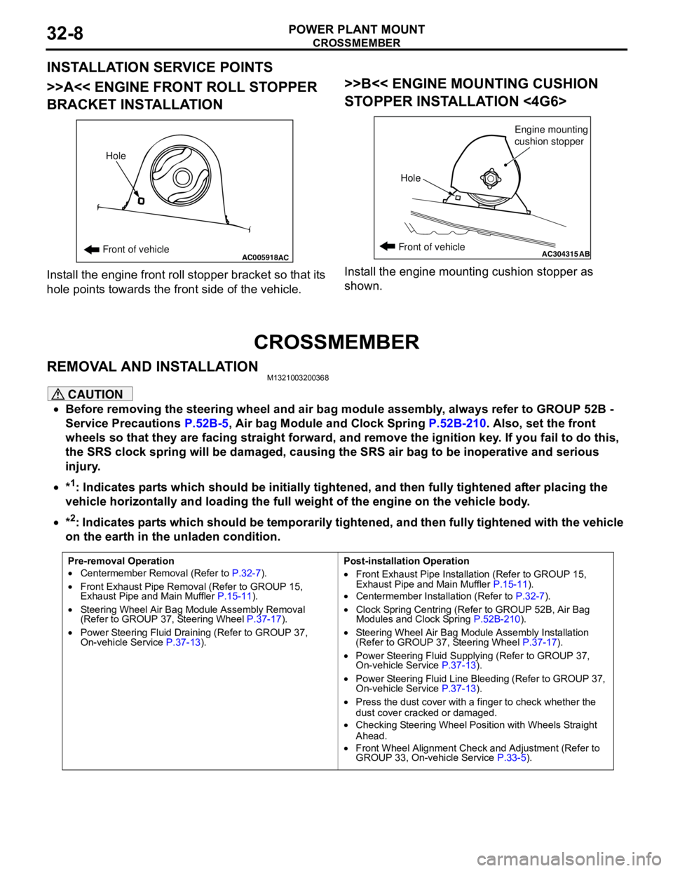
>>A<< ENGINE FRONT ROLL STOPPER
BRACKET INSTALLATION
Install the engine front roll stopper bracket so that its
hole points towards the front side of the vehicle.
>>B<< ENGINE MOUNTING CUSHION
STOPPER INSTALLATION <4G6>
Install the engine mounting cushion stopper as
shown.
CROSSMEMBER
REMOVAL AND INSTALLATIONM1321003200368
CAUTION
•Before removing the steering wheel and air bag module assembly, always refer to GROUP 52B -
Service Precautions P.52B-5, Air bag Module and Clock Spring P.52B-210. Also, set the front
wheels so that they are facing straight forward, and remove the ignition key. If you fail to do this,
the SRS clock spring will be damaged, causing the SRS air bag to be inoperative and serious
injury.
•*
1: Indicates parts which should be initially tightened, and then fully tightened after placing the
vehicle horizontally and loading the full weight of the engine on the vehicle body.
•*
2: Indicates parts which should be temporarily tightened, and then fully tightened with the vehicle
on the earth in the unladen condition.
AC005918Front of vehicleHoleACAC304315ABFront of vehicle
HoleEngine mounting
cushion stopper
Pre-removal Operation
•Centermember Removal (Refer to P.32-7).
•Front Exhaust Pipe Removal (Refer to GROUP 15,
Exhaust Pipe and Main Muffler P.15-11).
•Steering Wheel Air Bag Module Assembly Removal
(Refer to GROUP 37, Steering Wheel P.37-17).
•Power Steering Fluid Draining (Refer to GROUP 37,
On-vehicle Service P.37-13).Post-installation Operation
•Front Exhaust Pipe Installation (Refer to GROUP 15,
Exhaust Pipe and Main Muffler P.15-11).
•Centermember Installation (Refer to P.32-7).
•Clock Spring Centring (Refer to GROUP 52B, Air Bag
Modules and Clock Spring P.52B-210).
•Steering Wheel Air Bag Module Assembly Installation
(Refer to GROUP 37, Steering Wheel P.37-17).
•Power Steering Fluid Supplying (Refer to GROUP 37,
On-vehicle Service P.37-13).
•Power Steering Fluid Line Bleeding (Refer to GROUP 37,
On-vehicle Service P.37-13).
•Press the dust cover with a finger to check whether the
dust cover cracked or damaged.
•Checking Steering Wheel Position with Wheels Straight
Ahead.
•Front Wheel Alignment Check and Adjustment (Refer to
GROUP 33, On-vehicle Service P.33-5).
Page 179 of 788
CROSSMEMBER
POWER PLANT MOUNT32-9
AC304000
108 ± 10 N·m 25 ± 4 N·m 18 ± 2 N·m
70 ± 10 N·m
21 ± 4 N·m 21 ± 4 N·m
186 ± 10 N·m*
167 ± 9 N·m
49 ± 10 N·m 52 ± 7 N·m*45 ± 5 N·m*
70 ± 10 N·m57 ± 7 N·m 12 ± 2 N·m
5
4 10
9 11
8
12
1413 6
716
15
172
3
1
N
N
N
2 11
AB
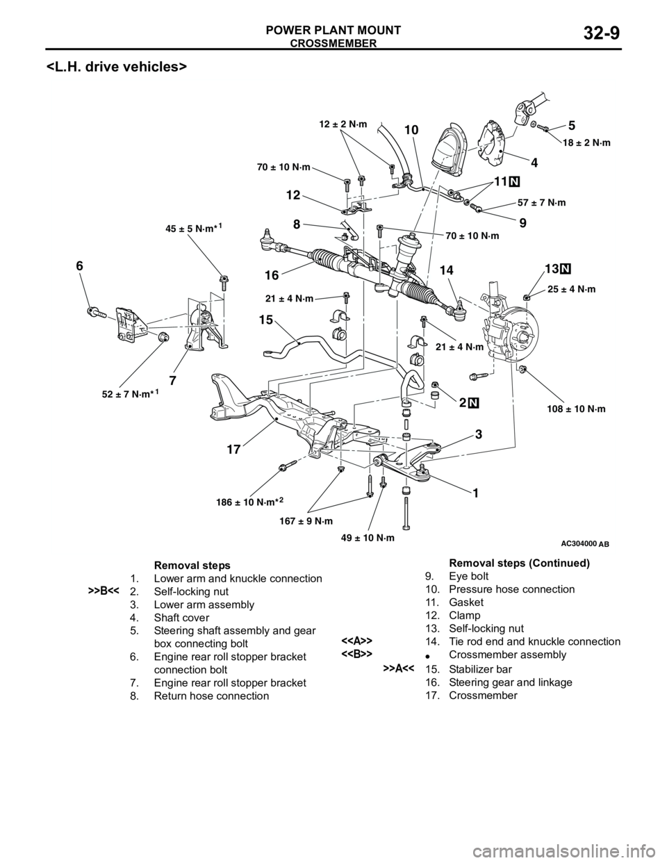
Removal steps
1. Lower arm and knuckle connection
>>B<<2. Self-locking nut
3. Lower arm assembly
4. Shaft cover
5. Steering shaft assembly and gear
box connecting bolt
6. Engine rear roll stopper bracket
connection bolt
7. Engine rear roll stopper bracket
8. Return hose connection9. Eye bolt
10. Pressure hose connection
11. Gasket
12. Clamp
13. Self-locking nut
<>14. Tie rod end and knuckle connection
<>•Crossmember assembly
>>A<<15. Stabilizer bar
16. Steering gear and linkage
17. CrossmemberRemoval steps (Continued)