lock MITSUBISHI LANCER 2005 User Guide
[x] Cancel search | Manufacturer: MITSUBISHI, Model Year: 2005, Model line: LANCER, Model: MITSUBISHI LANCER 2005Pages: 788, PDF Size: 45.98 MB
Page 71 of 788
CHARGING SYSTEM
ENGINE ELECTRICAL16-7
REGULATED VOLTAGE TESTM1161001100354
This test determines whether the voltage regulator
correctly controlling the alternator output voltage.
1. Always be sure to check the following before the
test.
•Alternator installation
•Check that the battery installed in the vehicle is
fully charged.
(Refer to GROUP 54A − Battery − On-vehicle
Service − Charging P.54A-4).
•Drive belt tension
(Refer to GROUP 11A − On-vehicle Service <4G1>
P.11A-7 or GROUP 11C − On-vehicle Service
<4G6> P.11C-7.)
•Fusible link
•Abnormal noise from the alternator while the
engine is running
2. Turn the ignition switch to the "LOCK" (OFF)
position.
3. Disconnect the negative battery cable.
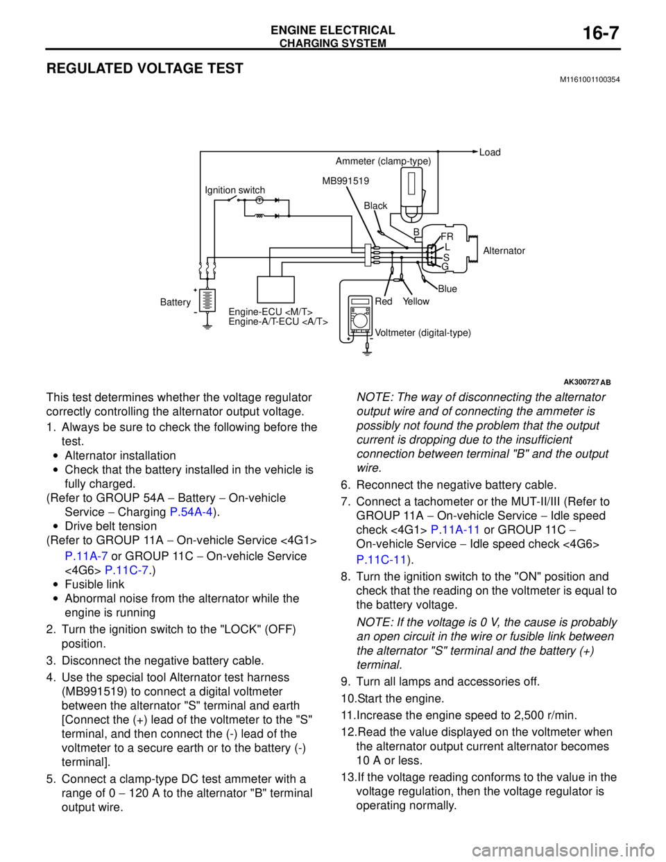
4. Use the special tool Alternator test harness
(MB991519) to connect a digital voltmeter
between the alternator "S" terminal and earth
[Connect the (+) lead of the voltmeter to the "S"
terminal, and then connect the (-) lead of the
voltmeter to a secure earth or to the battery (-)
terminal].
5. Connect a clamp-type DC test ammeter with a
range of 0 − 120 A to the alternator "B" terminal
output wire.NOTE: The way of disconnecting the alternator
output wire and of connecting the ammeter is
possibly not found the problem that the output
current is dropping due to the insufficient
connection between terminal "B" and the output
wire.
6. Reconnect the negative battery cable.
7. Connect a tachometer or the MUT-II/III (Refer to
GROUP 11A − On-vehicle Service − Idle speed
check <4G1> P.11A-11 or GROUP 11C −
On-vehicle Service − Idle speed check <4G6>
P.11C-11).
8. Turn the ignition switch to the "ON" position and
check that the reading on the voltmeter is equal to
the battery voltage.
NOTE: If the voltage is 0 V, the cause is probably
an open circuit in the wire or fusible link between
the alternator "S" terminal and the battery (+)
terminal.
9. Turn all lamps and accessories off.
10.Start the engine.
11.Increase the engine speed to 2,500 r/min.
12.Read the value displayed on the voltmeter when
the alternator output current alternator becomes
10 A or less.
13.If the voltage reading conforms to the value in the
voltage regulation, then the voltage regulator is
operating normally.
AK300727AB
BatteryIgnition switch
Engine-ECU
Engine-A/T-ECU Ammeter (clamp-type)Load
Black MB991519
Voltmeter (digital-type) Red
YellowBlueAlternator B
FR
L
S
G
Page 72 of 788

CHARGING SYSTEM
ENGINE ELECTRICAL16-8
If the voltage is not within the standard value,
there is a malfunction of the voltage regulator or of
the alternator.
14.After the test, lower the engine speed to the idle
speed.
15.Turn the ignition switch to the "LOCK" (OFF)
position.
16.Remove the tachometer or the MUT-II/III.17.Disconnect the negative battery cable.
18.Disconnect the ammeter and voltmeter.
19.Connect the alternator output wire to the
alternator "B" terminal.
20.Remove the special tool, and return the connector
to the original condition.
21.Connect the negative battery cable.
Voltage Regulation Table
Standard value:
Inspection terminal Voltage regulator ambient
temperature °CVoltage V
Terminal "S"
−2014.2 − 15.4
20 13.9 − 14.9
60 13.4 − 14.6
80 13.1 − 14.5
Page 91 of 788
Page 92 of 788
STARTING SYSTEM
ENGINE ELECTRICAL16-28
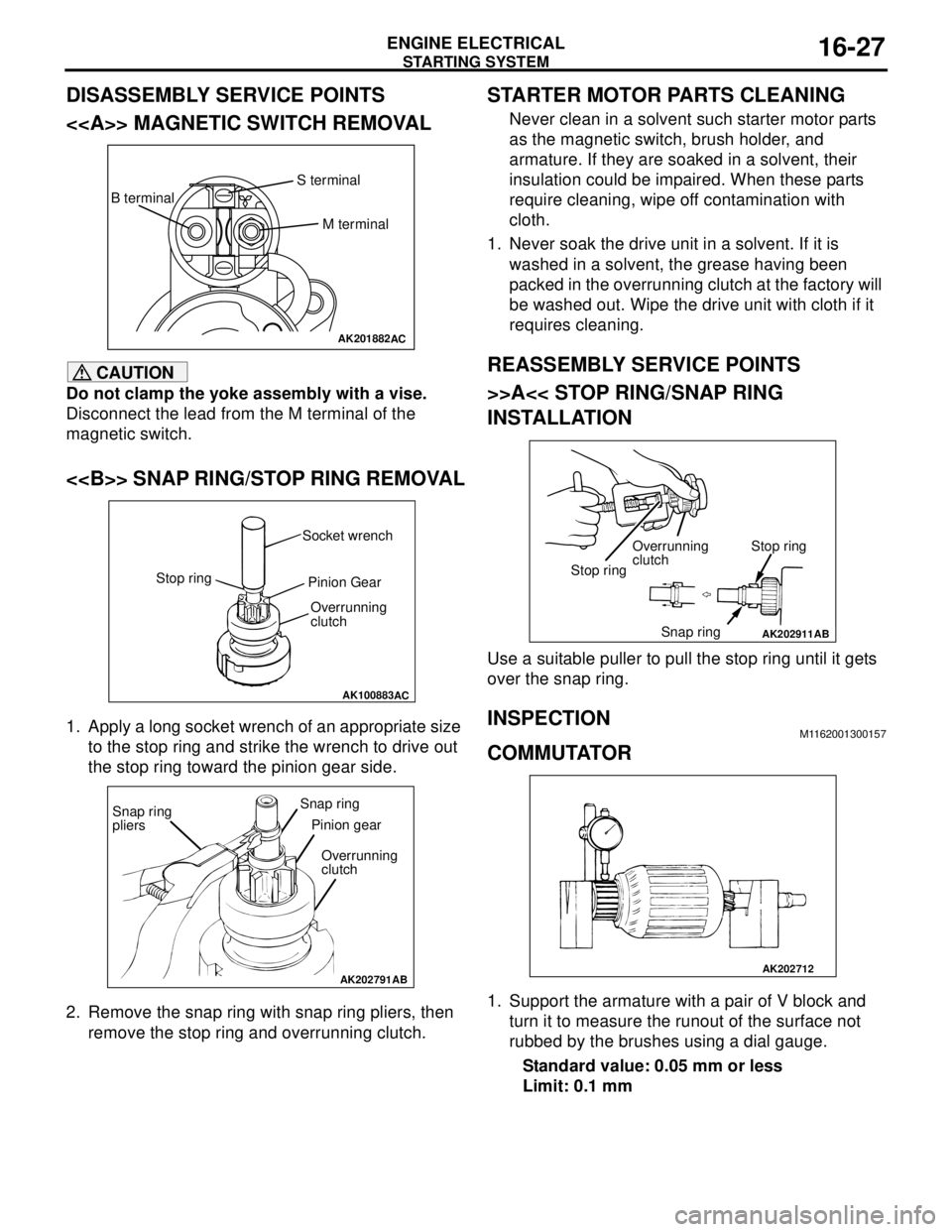
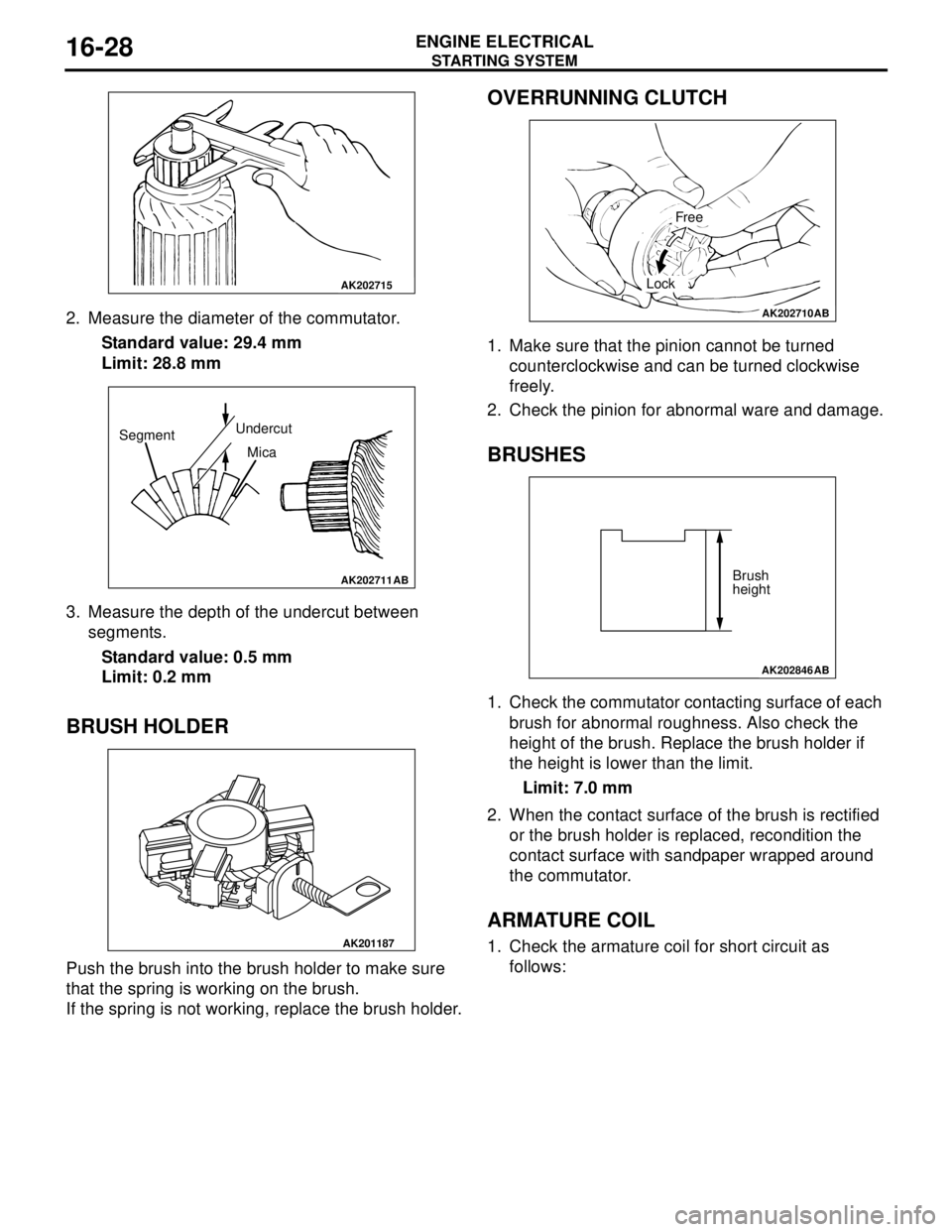
2. Measure the diameter of the commutator.
Standard value: 29.4 mm
Limit: 28.8 mm
3. Measure the depth of the undercut between
segments.
Standard value: 0.5 mm
Limit: 0.2 mm
BRUSH HOLDER
Push the brush into the brush holder to make sure
that the spring is working on the brush.
If the spring is not working, replace the brush holder.
OVERRUNNING CLUTCH
1. Make sure that the pinion cannot be turned
counterclockwise and can be turned clockwise
freely.
2. Check the pinion for abnormal ware and damage.
BRUSHES
1. Check the commutator contacting surface of each
brush for abnormal roughness. Also check the
height of the brush. Replace the brush holder if
the height is lower than the limit.
Limit: 7.0 mm
2. When the contact surface of the brush is rectified
or the brush holder is replaced, recondition the
contact surface with sandpaper wrapped around
the commutator.
ARMATURE COIL
1. Check the armature coil for short circuit as
follows:
AK202715
AK202711
SegmentUndercut
Mica
AB
AK201187
AK202710
Free
Lock
AB
AK202846
Brush
height
AB
Page 107 of 788
IGNITION SYSTEM
ENGINE ELECTRICAL16-43
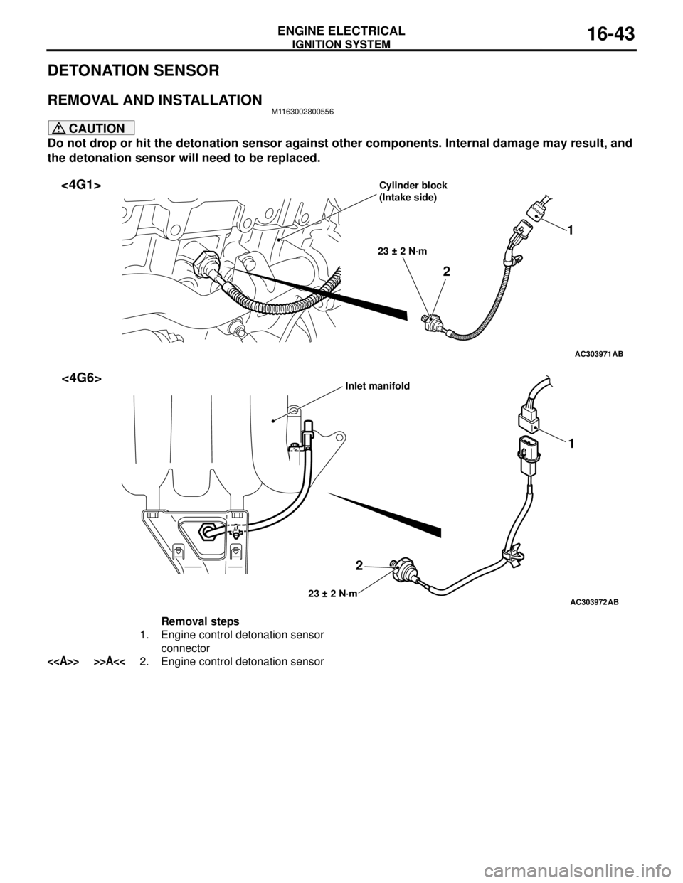
DETONATION SENSOR
REMOVAL AND INSTALLATIONM1163002800556
CAUTION
Do not drop or hit the detonation sensor against other components. Internal damage may result, and
the detonation sensor will need to be replaced.
AC303971
21
23 ± 2 N·m
AB
<4G1>Cylinder block
(Intake side)
AC303972
21
23 ± 2 N·mAB
<4G6>Inlet manifold
Removal steps
1. Engine control detonation sensor
connector
<> >>A<<2. Engine control detonation sensor
Page 110 of 788
ENGINE CONTROL
ENGINE AND EMISSION CONTROL17-2
ENGINE CONTROL
GENERAL INFORMATIONM1171000100277
A cable-type accelerator mechanical
suspended-type pedal has been adopted.
SERVICE SPECIFICATIONSM1171000300088
ON-VEHICLE SERVICE
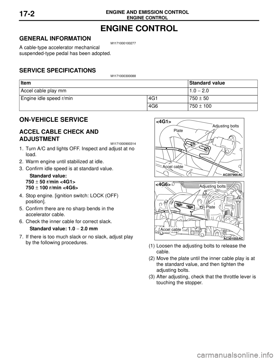
ACCEL CABLE CHECK AND
ADJUSTMENT
M1171000900314
1. Turn A/C and lights OFF. Inspect and adjust at no
load.
2. Warm engine until stabilized at idle.
3. Confirm idle speed is at standard value.
Standard value:
750 ± 50 r/min <4G1>
750 ± 100 r/min <4G6>
4. Stop engine. [ignition switch: LOCK (OFF)
position].
5. Confirm there are no sharp bends in the
accelerator cable.
6. Check the inner cable for correct slack.
Standard value: 1.0 − 2.0 mm
7. If there is too much slack or no slack, adjust play
by the following procedures.
(1) Loosen the adjusting bolts to release the
cable.
(2) Move the plate until the inner cable play is at
the standard value, and then tighten the
adjusting bolts.
(3) After adjusting, check that the throttle lever is
touching the stopper. Item Standard value
Accel cable play mm 1.0 − 2.0
Engine idle speed r/min 4G1 750 ± 50
4G6 750 ± 100
AC207966
Adjusting bolts
Plate
Accel cable
AC
<4G1>
AC301055
Adjusting bolts
Plate
Accel cable
AC
<4G6>
Page 119 of 788
EMISSION CONTROL
ENGINE AND EMISSION CONTROL17-11
1. Disconnect the vacuum hose (red stripe) from
throttle body and connect it to a hand vacuum
pump.
2. Plug the nipple from which the vacuum hose was
removed.
3. When the engine is cold or hot, apply a vacuum of
53 kPa, and check the condition of the vacuum.
When engine is cold
(Engine coolant temperature: 40°C or less)
When engine is hot
(Engine coolant temperature: 80°C or higher)
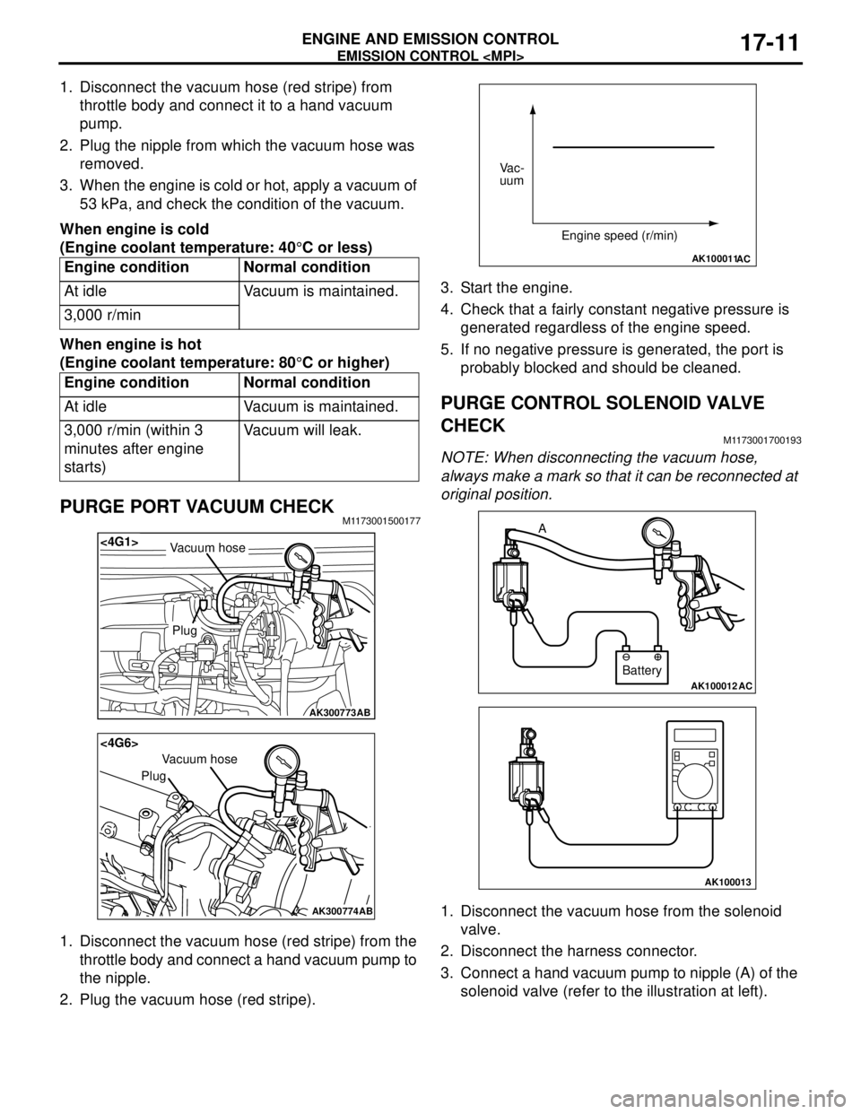
PURGE PORT VACUUM CHECKM1173001500177
1. Disconnect the vacuum hose (red stripe) from the
throttle body and connect a hand vacuum pump to
the nipple.
2. Plug the vacuum hose (red stripe).3. Start the engine.
4. Check that a fairly constant negative pressure is
generated regardless of the engine speed.
5. If no negative pressure is generated, the port is
probably blocked and should be cleaned.
PURGE CONTROL SOLENOID VALVE
CHECK
M1173001700193
NOTE: When disconnecting the vacuum hose,
always make a mark so that it can be reconnected at
original position.
1. Disconnect the vacuum hose from the solenoid
valve.
2. Disconnect the harness connector.
3. Connect a hand vacuum pump to nipple (A) of the
solenoid valve (refer to the illustration at left). Engine condition Normal condition
At idle Vacuum is maintained.
3,000 r/min
Engine condition Normal condition
At idle Vacuum is maintained.
3,000 r/min (within 3
minutes after engine
starts)Vacuum will leak.
AK300773
<4G1>
AB
Plug
Vacuum hose
AK300774
<4G6>
AB
Plug
Vacuum hose
AK100011AC
Vac-
uum
Engine speed (r/min)
AK100012AC
Battery A
AK100013
Page 124 of 788
EMISSION CONTROL
ENGINE AND EMISSION CONTROL17-16
5. Replace the gasket, and tighten to the specified
torque.
Tightening torque:
<4G1> 21 ± 4 N⋅m
<4G6> 20 ± 2 N⋅m
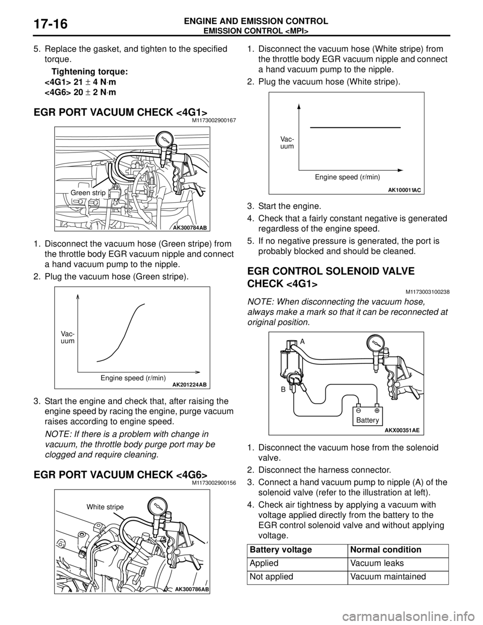
EGR PORT VACUUM CHECK <4G1>M1173002900167
1. Disconnect the vacuum hose (Green stripe) from
the throttle body EGR vacuum nipple and connect
a hand vacuum pump to the nipple.
2. Plug the vacuum hose (Green stripe).
3. Start the engine and check that, after raising the
engine speed by racing the engine, purge vacuum
raises according to engine speed.
NOTE: If there is a problem with change in
vacuum, the throttle body purge port may be
clogged and require cleaning.
EGR PORT VACUUM CHECK <4G6>M1173002900156
1. Disconnect the vacuum hose (White stripe) from
the throttle body EGR vacuum nipple and connect
a hand vacuum pump to the nipple.
2. Plug the vacuum hose (White stripe).
3. Start the engine.
4. Check that a fairly constant negative is generated
regardless of the engine speed.
5. If no negative pressure is generated, the port is
probably blocked and should be cleaned.
EGR CONTROL SOLENOID VALVE
CHECK <4G1>
M1173003100238
NOTE: When disconnecting the vacuum hose,
always make a mark so that it can be reconnected at
original position.
1. Disconnect the vacuum hose from the solenoid
valve.
2. Disconnect the harness connector.
3. Connect a hand vacuum pump to nipple (A) of the
solenoid valve (refer to the illustration at left).
4. Check air tightness by applying a vacuum with
voltage applied directly from the battery to the
EGR control solenoid valve and without applying
voltage.
AK300784AB
Green strip
AK201224AB
Vac-
uum
Engine speed (r/min)
AK300786AB
White stripe
Battery voltage Normal condition
Applied Vacuum leaks
Not applied Vacuum maintained
AK100011AC
Vac-
uum
Engine speed (r/min)
AKX00351
A
B
AE
Battery
Page 140 of 788
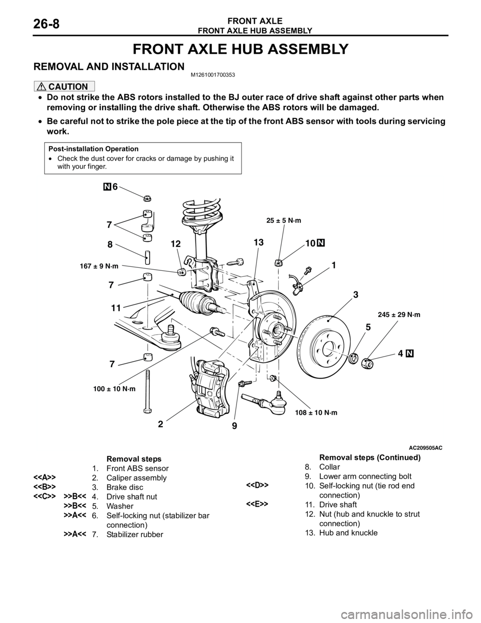
FRONT AXLE HUB ASSEMBLY
FRONT AXLE26-8
FRONT AXLE HUB ASSEMBLY
REMOVAL AND INSTALLATIONM1261001700353
CAUTION
•Do not strike the ABS rotors installed to the BJ outer race of drive shaft against other parts when
removing or installing the drive shaft. Otherwise the ABS rotors will be damaged.
•Be careful not to strike the pole piece at the tip of the front ABS sensor with tools during servicing
work.
Post-installation Operation
•Check the dust cover for cracks or damage by pushing it
with your finger.
AC209505
N
N
N
5
4 3 1 810
9 2 76
167 ± 9 N·m25 ± 5 N·m
108 ± 10 N·m245 ± 29 N·m
100 ± 10 N·m
AC
7
7
111213
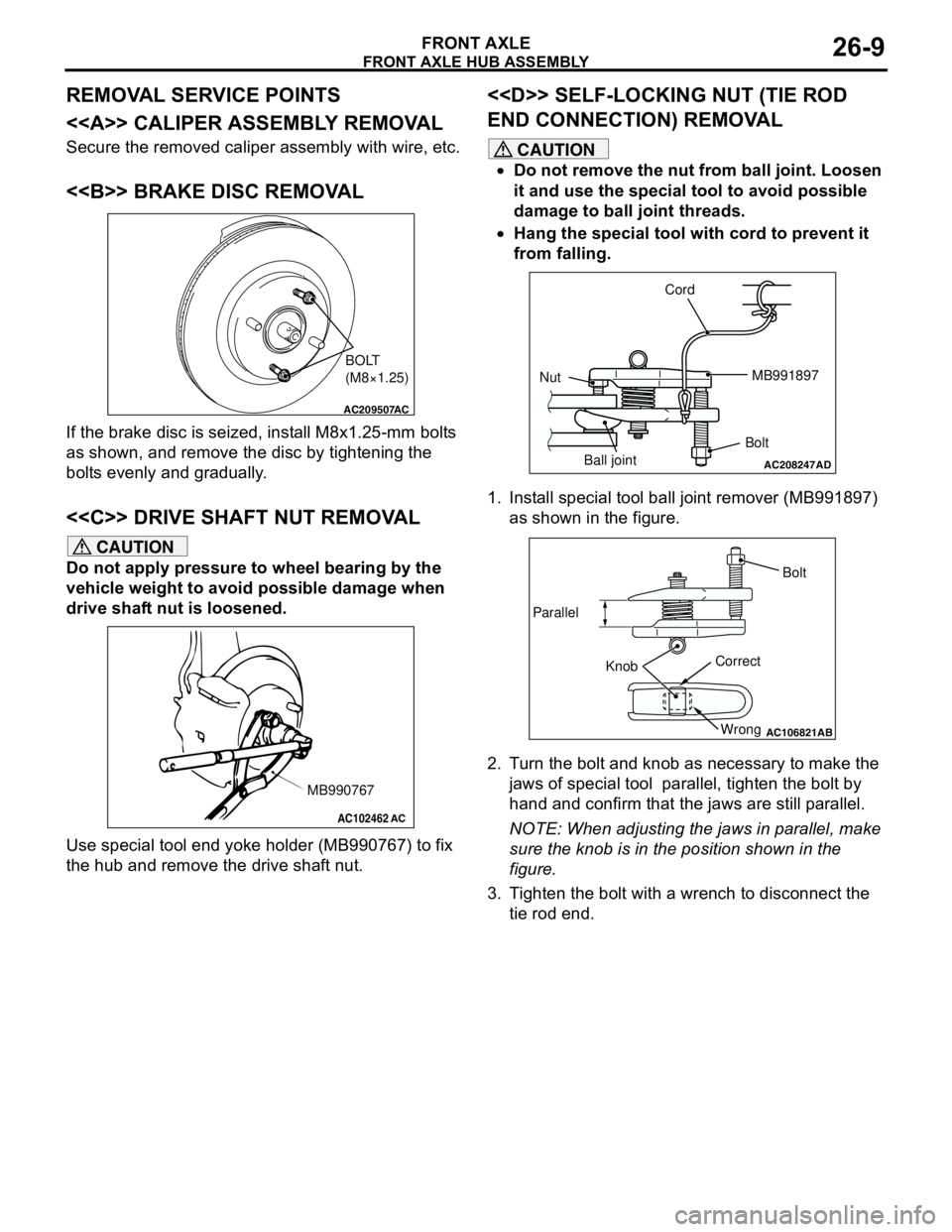
Removal steps
1. Front ABS sensor
<>
2. Caliper assembly
<>
3. Brake disc
<
>>B<<5. Washer
>>A<<6. Self-locking nut (stabilizer bar
connection)
>>A<<7. Stabilizer rubber8. Collar
9. Lower arm connecting bolt
<
10. Self-locking nut (tie rod end
connection)
<
11 . D r i v e s h a f t
12. Nut (hub and knuckle to strut
connection)
13. Hub and knuckle
Removal steps (Continued)
Page 141 of 788
