check MITSUBISHI LANCER 2005 Workshop Manual
[x] Cancel search | Manufacturer: MITSUBISHI, Model Year: 2005, Model line: LANCER, Model: MITSUBISHI LANCER 2005Pages: 788, PDF Size: 45.98 MB
Page 555 of 788
ON-VEHICLE SERVICE
HEATER, AIR CONDITIONER AND VENTILATION55-71
CAUTION
Do not operate the compressor in the vacuum
condition; damage may occur.
13.Loosen the valve of the adapter valve fully (valve
closed), and turn off the vacuum pump adapter
switch. Then leave it for five minutes.
14.Check the system for proper sealing (negative
pressure should not decrease).
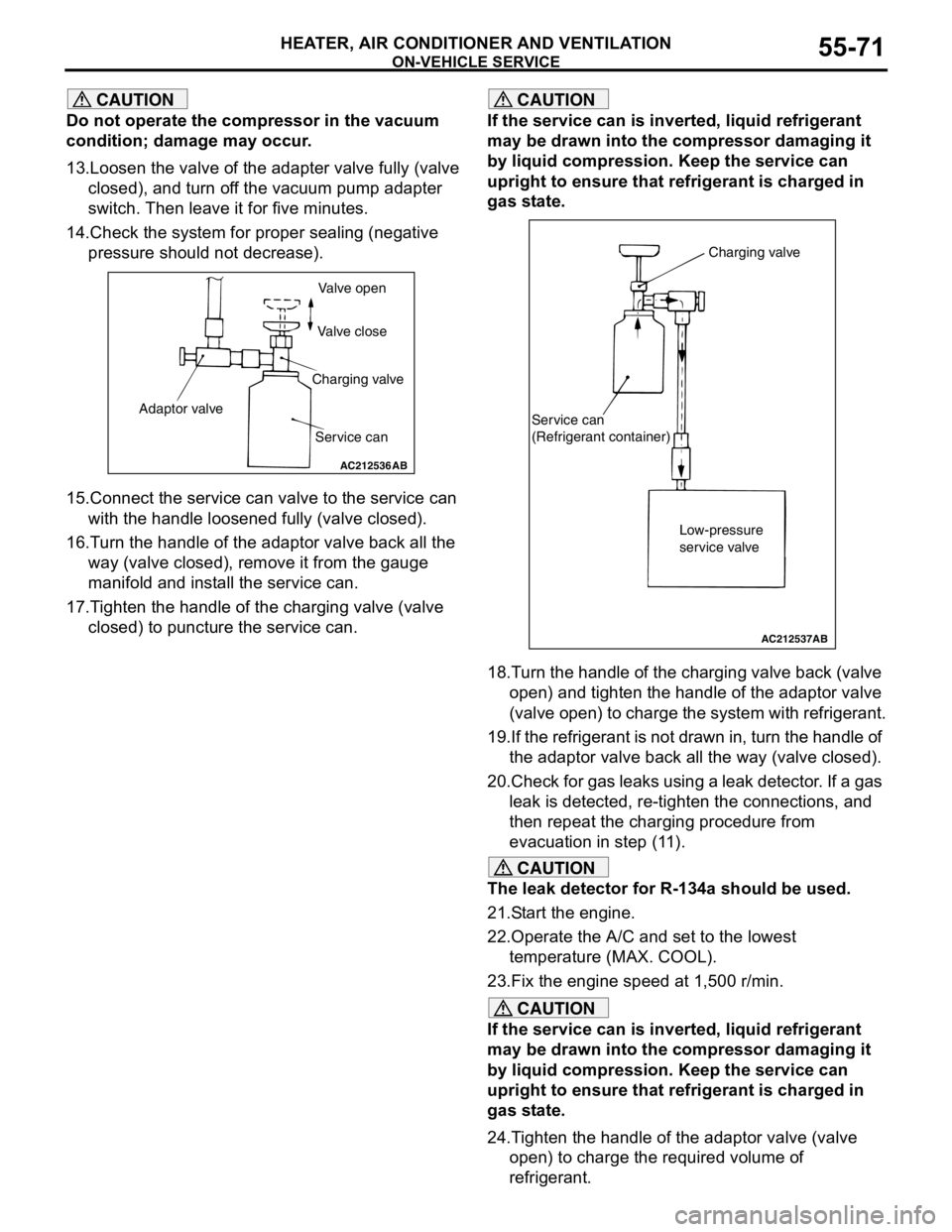
15.Connect the service can valve to the service can
with the handle loosened fully (valve closed).
16.Turn the handle of the adaptor valve back all the
way (valve closed), remove it from the gauge
manifold and install the service can.
17.Tighten the handle of the charging valve (valve
closed) to puncture the service can.
CAUTION
If the service can is inverted, liquid refrigerant
may be drawn into the compressor damaging it
by liquid compression. Keep the service can
upright to ensure that refrigerant is charged in
gas state.
18.Turn the handle of the charging valve back (valve
open) and tighten the handle of the adaptor valve
(valve open) to charge the system with refrigerant.
19.If the refrigerant is not drawn in, turn the handle of
the adaptor valve back all the way (valve closed).
20.Check for gas leaks using a leak detector. If a gas
leak is detected, re-tighten the connections, and
then repeat the charging procedure from
evacuation in step (11).
CAUTION
The leak detector for R-134a should be used.
21.Start the engine.
22.Operate the A/C and set to the lowest
temperature (MAX. COOL).
23.Fix the engine speed at 1,500 r/min.
CAUTION
If the service can is inverted, liquid refrigerant
may be drawn into the compressor damaging it
by liquid compression. Keep the service can
upright to ensure that refrigerant is charged in
gas state.
24.Tighten the handle of the adaptor valve (valve
open) to charge the required volume of
refrigerant.
AC212536
Valve open
Valve close
Charging valve
Service can Adaptor valve
AB
AC212537
Charging valve
Service can
(Refrigerant container)
Low-pressure
service valve
AB
Page 556 of 788
ON-VEHICLE SERVICE
HEATER, AIR CONDITIONER AND VENTILATION55-72
25.After charging with refrigerant, turn the handle of
the adaptor valve back all the way (valve closed).
26.Tighten the charging valve handle (valve closed).
Remove the quick joint (for low-pressure) from the
low-pressure service valve.
27.Remove the service can.
NOTE: If the service can is not emptied
completely, keep the handles of the charging
valve and adaptor valve closed for the next
charging.
CORRECTING LOW REFRIGERANT
LEVEL IN CASE THE SERVICE CAN IN
USED
M1552014600100
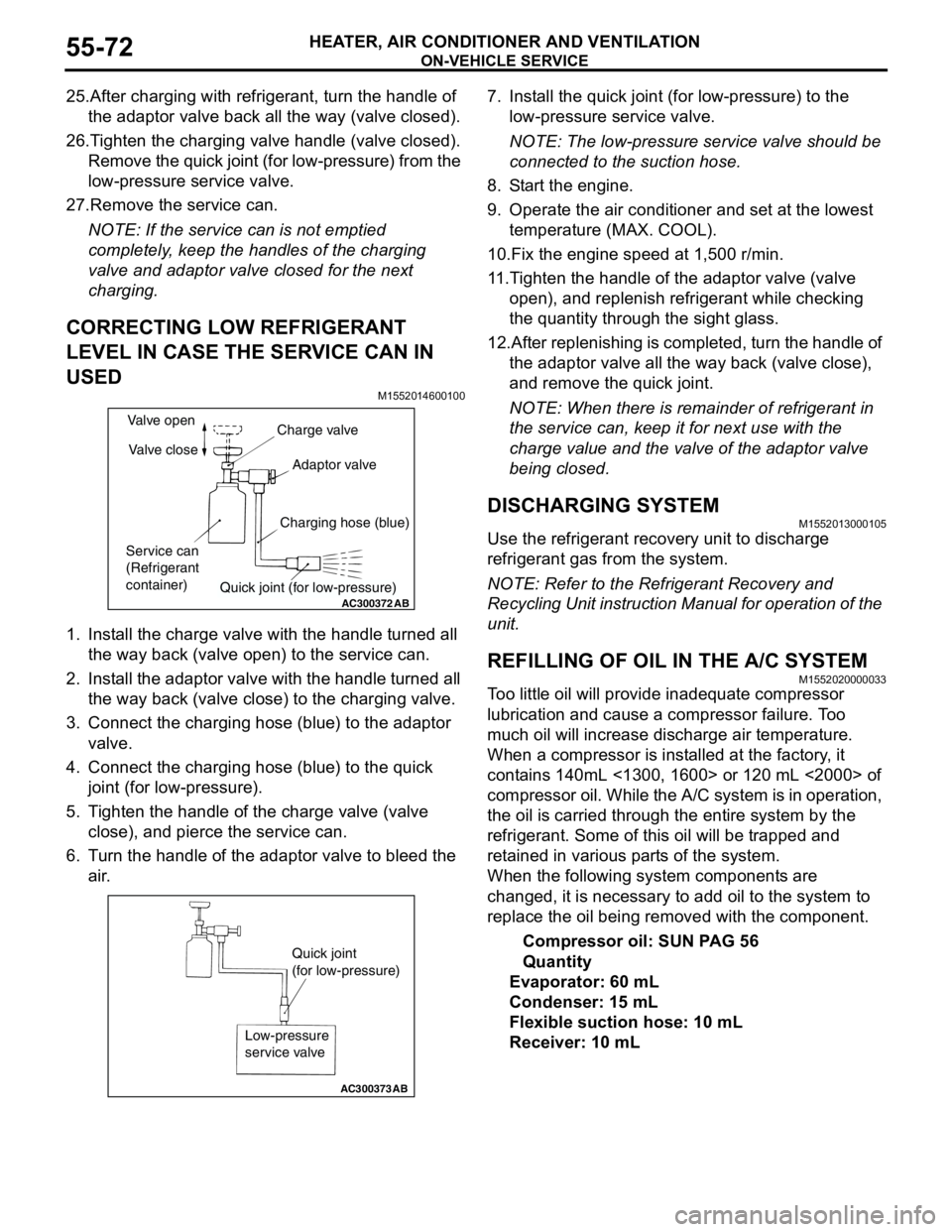
1. Install the charge valve with the handle turned all
the way back (valve open) to the service can.
2. Install the adaptor valve with the handle turned all
the way back (valve close) to the charging valve.
3. Connect the charging hose (blue) to the adaptor
valve.
4. Connect the charging hose (blue) to the quick
joint (for low-pressure).
5. Tighten the handle of the charge valve (valve
close), and pierce the service can.
6. Turn the handle of the adaptor valve to bleed the
air.7. Install the quick joint (for low-pressure) to the
low-pressure service valve.
NOTE: The low-pressure service valve should be
connected to the suction hose.
8. Start the engine.
9. Operate the air conditioner and set at the lowest
temperature (MAX. COOL).
10.Fix the engine speed at 1,500 r/min.
11.Tighten the handle of the adaptor valve (valve
open), and replenish refrigerant while checking
the quantity through the sight glass.
12.After replenishing is completed, turn the handle of
the adaptor valve all the way back (valve close),
and remove the quick joint.
NOTE: When there is remainder of refrigerant in
the service can, keep it for next use with the
charge value and the valve of the adaptor valve
being closed.
DISCHARGING SYSTEMM1552013000105
Use the refrigerant recovery unit to discharge
refrigerant gas from the system.
NOTE: Refer to the Refrigerant Recovery and
Recycling Unit instruction Manual for operation of the
unit.
REFILLING OF OIL IN THE A/C SYSTEMM1552020000033
Too little oil will provide inadequate compressor
lubrication and cause a compressor failure. Too
much oil will increase discharge air temperature.
When a compressor is installed at the factory, it
contains 140mL <1300, 1600> or 120 mL <2000> of
compressor oil. While the A/C system is in operation,
the oil is carried through the entire system by the
refrigerant. Some of this oil will be trapped and
retained in various parts of the system.
When the following system components are
changed, it is necessary to add oil to the system to
replace the oil being removed with the component.
Compressor oil: SUN PAG 56
Quantity
Evaporator: 60 mL
Condenser: 15 mL
Flexible suction hose: 10 mL
Receiver: 10 mL
AC300372
AB
Valve open
Valve close
Service can
(Refrigerant
container)Charge valve
Adaptor valve
Charging hose (blue)
Quick joint (for low-pressure)
AC300373
Quick joint
(for low-pressure)
Low-pressure
service valve
AB
Page 558 of 788
ON-VEHICLE SERVICE
HEATER, AIR CONDITIONER AND VENTILATION55-74
REFRIGERANT LEAK REPAIR
PROCEDURE
M1552001500277
LOST CHARGE
If the system has lost all charge due to a leak:
1. Evacuate the system (Refer to P.55-72).
2. Charge the system with approximately 480 − 520
g of refrigerant.
3. Check for leaks.
4. Discharge the system.
5. Repair leaks.
CAUTION
Replacement filter-drier units must be sealed
while in storage. The drier used in these units will
saturate water quickly upon exposure to the
atmosphere. When installing a drier, have all
tools and supplies ready for quick assembly to
avoid keeping the system open any longer than
necessary.
6. Replace receiver drier.
7. Evacuate and charge system.
LOW CHARGE
If the system has not lost all of its refrigerant charge;
locate and repair all leaks. If it is necessary to
increase the system pressure to find the leak
(because of an especially low charge) add
refrigerant. If it is possible to repair the leak without
discharging the refrigerant system, use the
procedure for correcting low refrigerant level.
HANDLING TUBING AND FITTINGS
Kinks in the refrigerant tubing or sharp bends in the
refrigerant hose lines will greatly reduce the capacity
of the entire system. High pressures are produced in
the system when it is operating. Extreme care must
be exercised to make sure that all connections are
pressure tight. Dirt and moisture can enter the
system when it is opened for repair or replacement of
lines or components. The following precautions must
be observed. The system must be completely
discharged before opening any fitting of connection
in the refrigeration system. Open fittings with caution
even after the system has been discharged. If any
pressure is noticed as a fitting is loosened, allow
trapped pressure to bleed off very slowly.
Never attempt to rebend formed lines to fit. Use the
correct line for the installation you are servicing. A
good rule for the flexible hose lines is keep the radius
of all bends at least 10 times the diameter of the
hose.Sharper bends will reduce the flow of refrigerant. The
flexible hose lines should be routed so that they are
at least 80 mm from the exhaust manifold. It is good
practice to inspect all flexible hose lines at least once
a year to make sure they are in good condition and
properly routed.
On standard plumbing fittings with O-rings, these
O-rings are not reusable.
COMPRESSOR NOISE CHECKM1552008700272
You must first know the conditions when the noise
occurs. These conditions are: weather, vehicle
speed, in gear or neutral, engine temperature or any
other special conditions.
Noises that develop during A/C operation can often
be misleading. For example: what sounds like a
failed front bearing or connecting rod, may be
caused by loose bolts, nuts, mounting brackets, or a
loose clutch assembly. Verify accessory drive belt
tension (power steering or alternator).
Improper accessory drive belt tension can cause a
misleading noise when the compressor is engaged
and little or no noise when the compressor is
disengaged.
Drive belts are speed-sensitive. That is, at different
engine speeds, and depending upon belt tension,
belts can develop unusual noises that are often
mistaken for mechanical problems within the
compressor.
ADJUSTMENT
1. Select a quiet area for testing. Duplicate
conditions as much as possible. Switch the
compressor on and off several times to clearly
identify compressor noise. To duplicate high
ambient conditions (high head pressure), restrict
air flow through the condenser. Install a manifold
gauge set to make sure discharge pressure
doesn't exceed 2,070 kPa.
2. Tighten all compressor mounting bolts, clutch
mounting bolt, and compressor drive belt. Check
to assure clutch coil is tight (no rotation or
wobble).
3. Check refrigerant hoses for rubbing or
interference that can cause unusual noises.
4. Check refrigerant charge (Refer to P.55-69).
5. Recheck compressor noise as in Step 1.
6. If noise still exists, loosen compressor mounting
bolts and retighten. Repeat Step 1.
7. If noise continues, replace compressor and repeat
Step 1.
Page 559 of 788
ON-VEHICLE SERVICE
HEATER, AIR CONDITIONER AND VENTILATION55-75
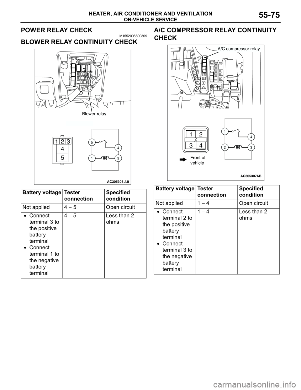
POWER RELAY CHECKM1552008800309
BLOWER RELAY CONTINUITY CHECKA/C COMPRESSOR RELAY CONTINUITY
CHECK
Battery voltage Tester
connectionSpecified
condition
Not applied 4 − 5 Open circuit
•Connect
terminal 3 to
the positive
battery
terminal
•Connect
terminal 1 to
the negative
battery
terminal4 − 5 Less than 2
ohms
AC305308
4
5 1
235
14
3
Blower relay
AB
Battery voltage Tester
connectionSpecified
condition
Not applied 1 − 4 Open circuit
•Connect
terminal 2 to
the positive
battery
terminal
•Connect
terminal 3 to
the negative
battery
terminal1 − 4 Less than 2
ohms
AC305307
A/C compressor relay
AB
21
34
1
24
3
Front of
vehicle
Page 560 of 788
ON-VEHICLE SERVICE
HEATER, AIR CONDITIONER AND VENTILATION55-76
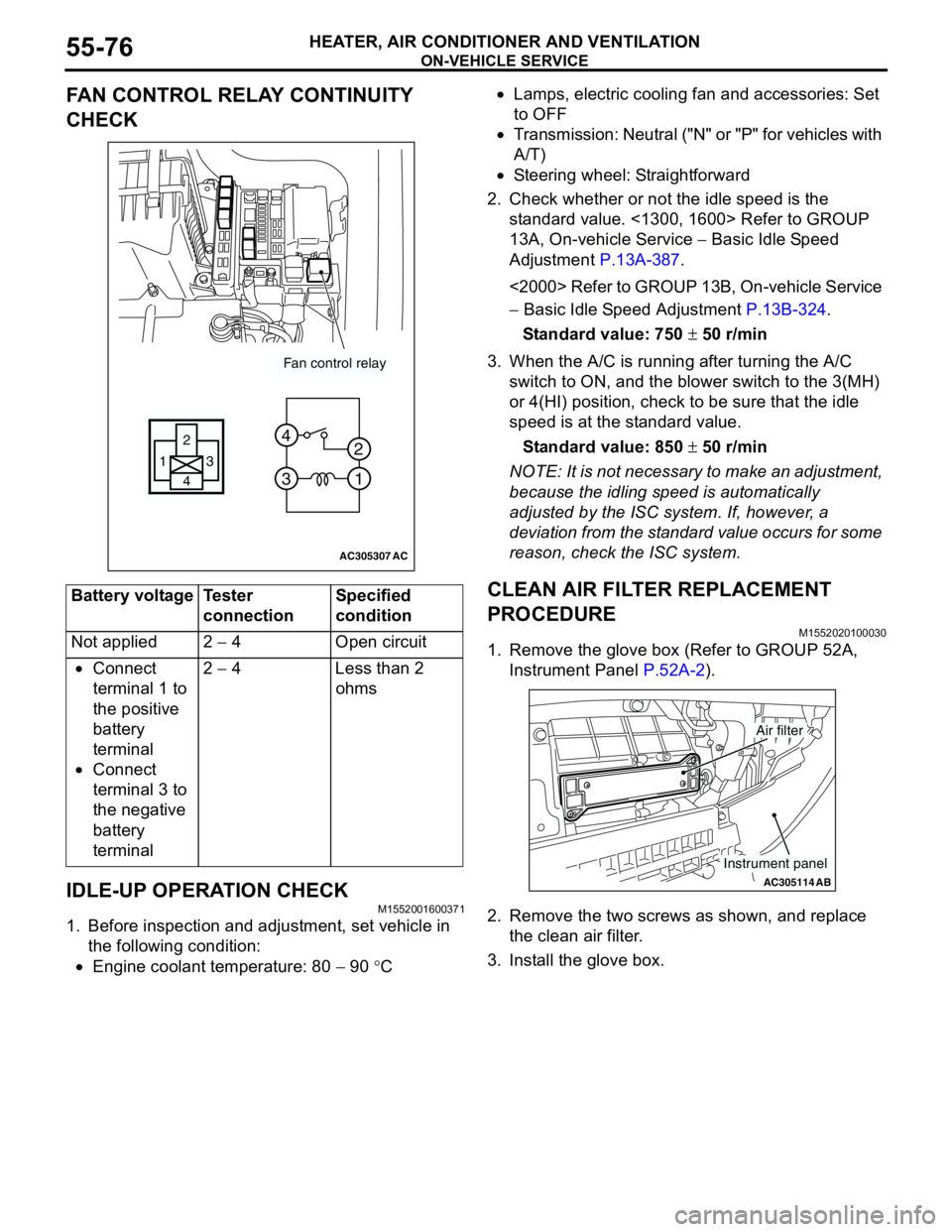
FAN CONTROL RELAY CONTINUITY
CHECK
IDLE-UP OPERATION CHECK
M1552001600371
1. Before inspection and adjustment, set vehicle in
the following condition:
•Engine coolant temperature: 80 − 90 °C•Lamps, electric cooling fan and accessories: Set
to OFF
•Transmission: Neutral ("N" or "P" for vehicles with
A/T)
•Steering wheel: Straightforward
2. Check whether or not the idle speed is the
standard value. <1300, 1600> Refer to GROUP
13A, On-vehicle Service − Basic Idle Speed
Adjustment P.13A-387.
<2000> Refer to GROUP 13B, On-vehicle Service
− Basic Idle Speed Adjustment P.13B-324.
Standard value: 750 ± 50 r/min
3. When the A/C is running after turning the A/C
switch to ON, and the blower switch to the 3(MH)
or 4(HI) position, check to be sure that the idle
speed is at the standard value.
Standard value: 850 ± 50 r/min
NOTE: It is not necessary to make an adjustment,
because the idling speed is automatically
adjusted by the ISC system. If, however, a
deviation from the standard value occurs for some
reason, check the ISC system.
CLEAN AIR FILTER REPLACEMENT
PROCEDURE
M1552020100030
1. Remove the glove box (Refer to GROUP 52A,
Instrument Panel P.52A-2).
2. Remove the two screws as shown, and replace
the clean air filter.
3. Install the glove box. Battery voltage Tester
connectionSpecified
condition
Not applied 2 − 4 Open circuit
•Connect
terminal 1 to
the positive
battery
terminal
•Connect
terminal 3 to
the negative
battery
terminal2 − 4 Less than 2
ohms
AC305307
Fan control relay
13
4 2
3 4
1 2
AC
AC305114AB
Air filter
Instrument panel
Page 563 of 788
HEATER CONTROL ASSEMBLY AND A/C SWITCH
HEATER, AIR CONDITIONER AND VENTILATION55-79
INSPECTIONM1552014300927
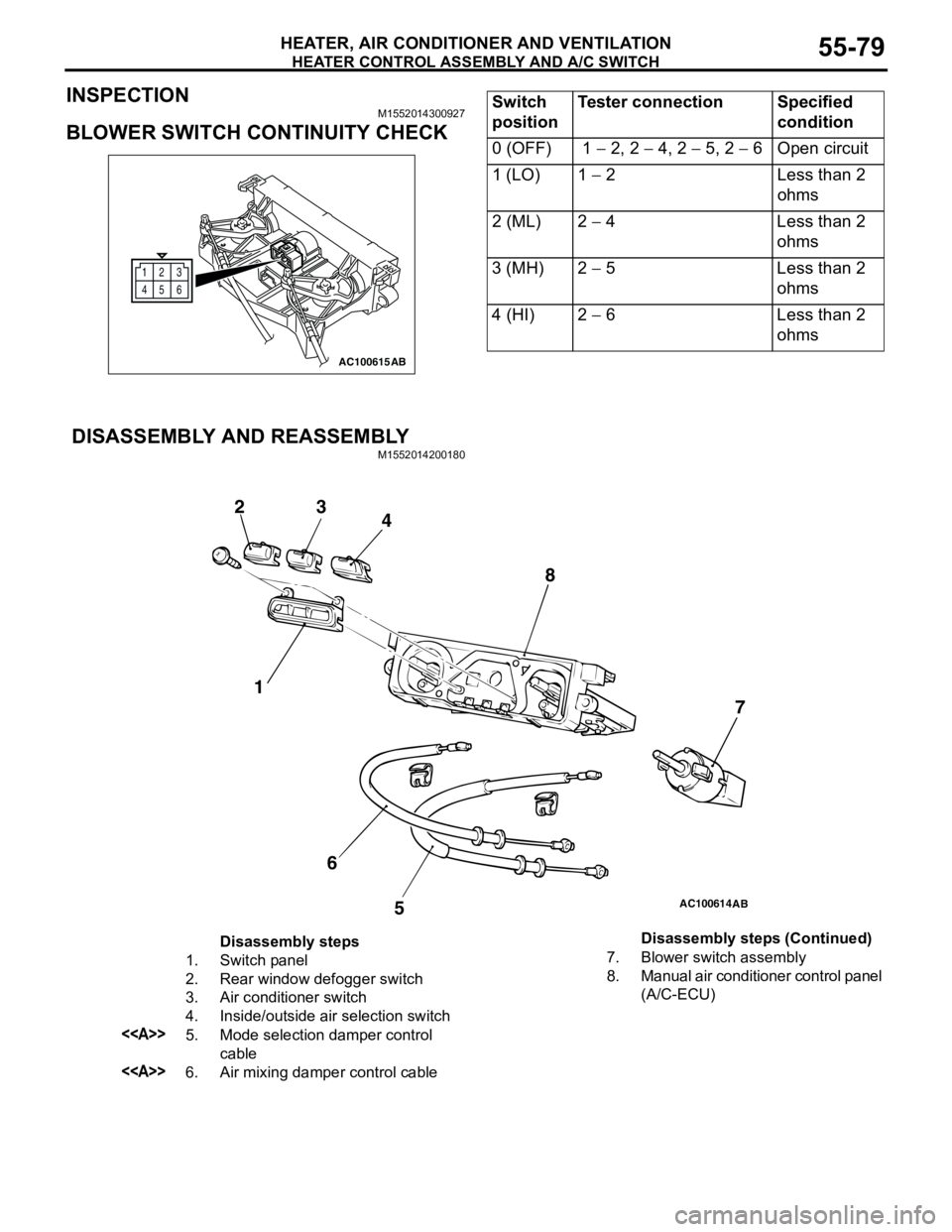
BLOWER SWITCH CONTINUITY CHECK
DISASSEMBLY AND REASSEMBLY
M1552014200180
12
6 3
45
AC100615AB
Switch
positionTester connection Specified
condition
0 (OFF) 1 − 2, 2 − 4, 2 − 5, 2 − 6 Open circuit
1 (LO) 1 − 2 Less than 2
ohms
2 (ML) 2 − 4 Less than 2
ohms
3 (MH) 2 − 5 Less than 2
ohms
4 (HI) 2 − 6 Less than 2
ohms
AC100614
1 23
4
5 67 8
AB
Disassembly steps
1. Switch panel
2. Rear window defogger switch
3. Air conditioner switch
4. Inside/outside air selection switch
<>5. Mode selection damper control
cable
<>6. Air mixing damper control cable7. Blower switch assembly
8. Manual air conditioner control panel
(A/C-ECU) Disassembly steps (Continued)
Page 570 of 788
BLOWERMOTOR, RESISTOR AND OUTSIDE/ INSIDE AIR SELECTION DAMPER CONTROL MOTOR
HEATER, AIR CONDITIONER AND VENTILATION55-86
REMOVAL SERVICE POINT
<> BLOWER MOTOR REMOVAL
NOTE:
Use of commercially available offset screw driver is
recommended.
INSPECTIONM1551006300275
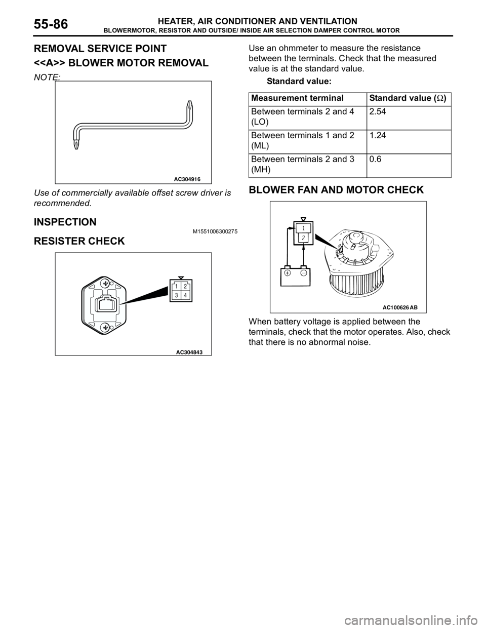
RESISTER CHECK
Use an ohmmeter to measure the resistance
between the terminals. Check that the measured
value is at the standard value.
Standard value:
BLOWER FAN AND MOTOR CHECK
When battery voltage is applied between the
terminals, check that the motor operates. Also, check
that there is no abnormal noise.
AC304916
12
34
AC304843
Measurement terminal Standard value (Ω)
Between terminals 2 and 4
(LO)2.54
Between terminals 1 and 2
(ML)1.24
Between terminals 2 and 3
(MH)0.6
AC100626AB
Page 571 of 788
BLOWERMOTOR, RESISTOR AND OUTSIDE/ INSIDE AIR SELECTION DAMPER CONTROL MOTOR
HEATER, AIR CONDITIONER AND VENTILATION55-87
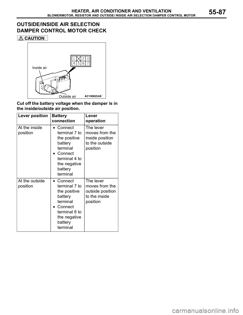
OUTSIDE/INSIDE AIR SELECTION
DAMPER CONTROL MOTOR CHECK
CAUTION
Cut off the battery voltage when the damper is in
the inside/outside air position.
Lever position Battery
connectionLever
operation
At the inside
position•Connect
terminal 7 to
the positive
battery
terminal
•Connect
terminal 4 to
the negative
battery
terminalThe lever
moves from the
inside position
to the outside
position
At the outside
position•Connect
terminal 7 to
the positive
battery
terminal
•Connect
terminal 6 to
the negative
battery
terminalThe lever
moves from the
outside position
to the inside
position
AC100625
Inside air
Outside air
AE
Page 574 of 788
Page 575 of 788
COMPRESSOR ASSEMBLY AND TENSION PULLEY
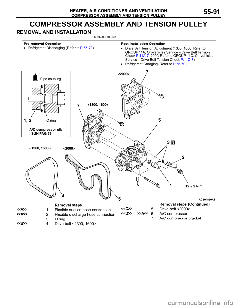
HEATER, AIR CONDITIONER AND VENTILATION55-91
COMPRESSOR ASSEMBLY AND TENSION PULLEY
REMOVAL AND INSTALLATIONM1552004100472
Pre-removal Operation
•Refrigerant Discharging (Refer to P.55-72).Post-installation Operation
•Drive Belt Tension Adjustment (1300, 1600: Refer to
GROUP 11A, On-vehicles Service − Drive Belt Tension
Check P.11A-7, 2000: Refer to GROUP 11C, On-vehicles
Service − Drive Belt Tension Check P.11C-7).
•Refrigerant Charging (Refer to P.55-70).
AC304850
1, 2
A/C compressor oil:
SUN PAG 56-Pipe coupling
O ring
12 ± 2 N·m
N
12 3 5
AB
7
54
7
<1300, 1600>
<1300, 1600><2000>
<2000>
Removal steps
<>1. Flexible suction hose connection
<>2. Flexible discharge hose connection
3. O ring
<>4. Drive belt <1300, 1600>
<
<
7. A/C compressor bracketRemoval steps (Continued)