Wheel MITSUBISHI LANCER 2005 Service Manual
[x] Cancel search | Manufacturer: MITSUBISHI, Model Year: 2005, Model line: LANCER, Model: MITSUBISHI LANCER 2005Pages: 788, PDF Size: 45.98 MB
Page 206 of 788
ON-VEHICLE SERVICE
REAR SUSPENSION34-6
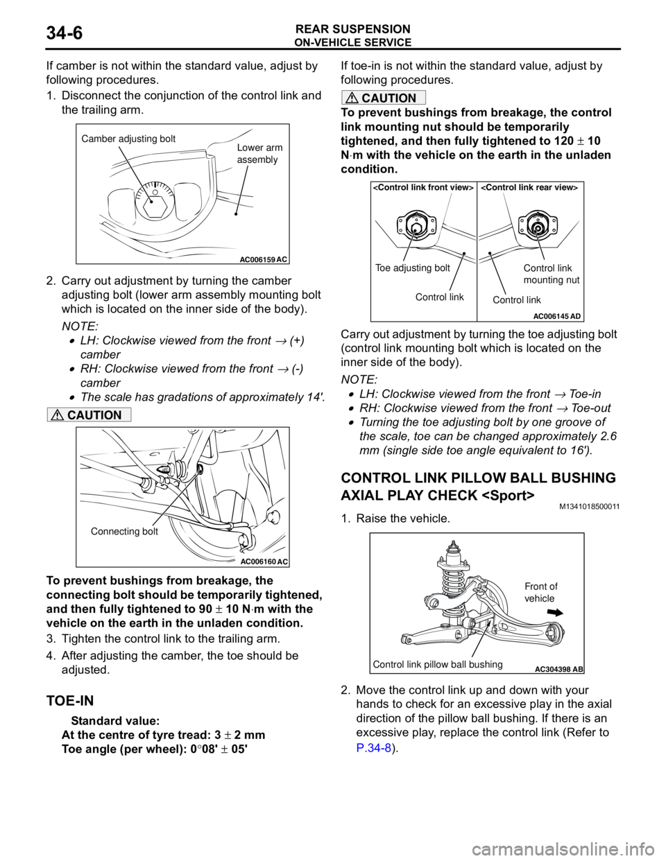
If camber is not within the standard value, adjust by
following procedures.
1. Disconnect the conjunction of the control link and
the trailing arm.
2. Carry out adjustment by turning the camber
adjusting bolt (lower arm assembly mounting bolt
which is located on the inner side of the body).
NOTE: .
•LH: Clockwise viewed from the front → (+)
camber
•RH: Clockwise viewed from the front → (-)
camber
•The scale has gradations of approximately 14'.
CAUTION
To prevent bushings from breakage, the
connecting bolt should be temporarily tightened,
and then fully tightened to 90 ± 10 N⋅m with the
vehicle on the earth in the unladen condition.
3. Tighten the control link to the trailing arm.
4. After adjusting the camber, the toe should be
adjusted.
TOE-IN
Standard value:
At the centre of tyre tread: 3 ± 2 mm
Toe angle (per wheel): 0°08' ± 05'If toe-in is not within the standard value, adjust by
following procedures.
CAUTION
To prevent bushings from breakage, the control
link mounting nut should be temporarily
tightened, and then fully tightened to 120 ± 10
N⋅m with the vehicle on the earth in the unladen
condition.
Carry out adjustment by turning the toe adjusting bolt
(control link mounting bolt which is located on the
inner side of the body).
NOTE: .
•LH: Clockwise viewed from the front → Toe-in
•RH: Clockwise viewed from the front → Toe-out
•Turning the toe adjusting bolt by one groove of
the scale, toe can be changed approximately 2.6
mm (single side toe angle equivalent to 16').
CONTROL LINK PILLOW BALL BUSHING
AXIAL PLAY CHECK
M1341018500011
1. Raise the vehicle.
2. Move the control link up and down with your
hands to check for an excessive play in the axial
direction of the pillow ball bushing. If there is an
excessive play, replace the control link (Refer to
P.34-8).
AC006159AC
Camber adjusting bolt
Lower arm
assembly
AC006160
AC
Connecting bolt
AC006145AD
Control link Toe adjusting boltControl link
Control link
mounting nut
AC304398ABControl link pillow ball bushing
Front of
vehicle
Page 208 of 788
CONTROL LINK, UPPER ARM AND LOWER ARM
REAR SUSPENSION34-8
CONTROL LINK, UPPER ARM AND LOWER ARM
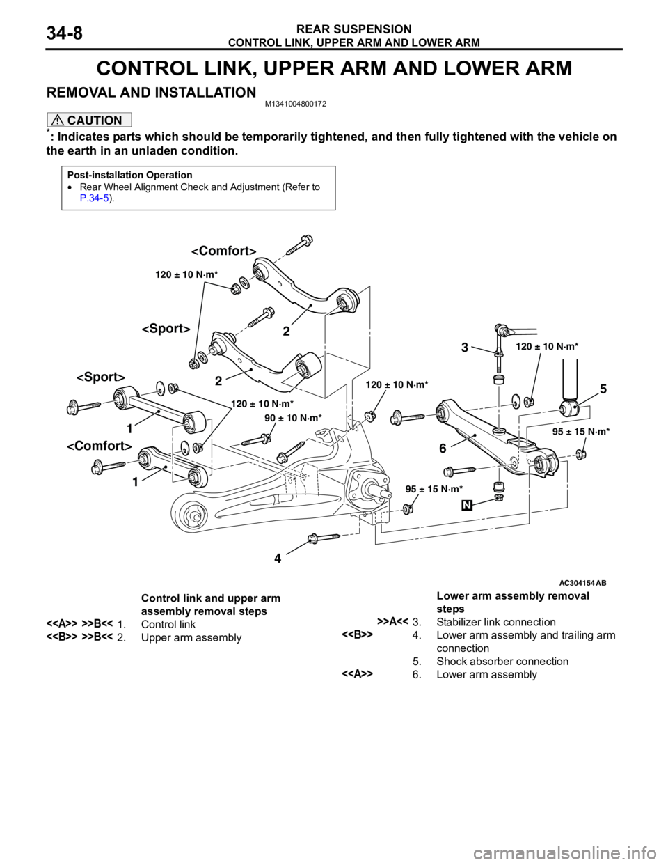
REMOVAL AND INSTALLATIONM1341004800172
CAUTION
*: Indicates parts which should be temporarily tightened, and then fully tightened with the vehicle on
the earth in an unladen condition.
Post-installation Operation
•Rear Wheel Alignment Check and Adjustment (Refer to
P.34-5).
AC304154
12
3
45
6
AB
120 ± 10 N·m*
95 ± 15 N·m* 120 ± 10 N·m* 120 ± 10 N·m*
95 ± 15 N·m*
90 ± 10 N·m*120 ± 10 N·m*
N
Control link and upper arm
assembly removal steps
<> >>B<<1. Control link
<> >>B<<2. Upper arm assemblyLower arm assembly removal
steps
>>A<<3. Stabilizer link connection
<>4. Lower arm assembly and trailing arm
connection
5. Shock absorber connection
<>6. Lower arm assembly
Page 212 of 788

TRAILING ARM ASSEMBLY
REAR SUSPENSION34-12
TRAILING ARM ASSEMBLY
REMOVAL AND INSTALLATIONM1341002200594
CAUTION
*: Indicates parts which should be temporarily tightened, and then fully tightened with the vehicle on
the earth in the unladen condition.
Pre-removal Operation
•Brake Fluid Draining
•Rear Hub Assembly Removal (Refer to GROUP 27, Rear
Axle Hub Assembly P.27-5).Post-installation Operation
•Rear Hub Assembly Installation (Refer to GROUP 27,
Rear Axle Hub Assembly P.27-5).
•Brake Fluid Supplying and Bleeding (Refer to GROUP
35A, On-vehicle Service − Bleeding P.35A-6).
•Rear Wheel Alignment Check and Adjustment (Refer to
P.34-5).
•Parking Brake Lever Stroke Adjustment (Refer to GROUP
36, On-vehicle Service − Parking Brake Lever Stroke
Check and Adjustment P.36-3).
AC101449
AC301223
AC304155AB
90 ± 10 N·m*
120 ± 10 N·m*
95 ± 15 N·m*63 ± 7 N·m
6 78
1 1011
23
4
120 ± 10 N·m*
15 ± 2 N·m
N
9
5
Removal steps
<>•Lifting point
1. Rear ABS Sensor (Refer to
GROUP 35B, ABS Sensor
P.35B-71).
2. Parking brake cable
3. Brake hose and trailing arm
connection
4. Rear parking brake assembly>>A<<5. Lower arm assembly and stabilizer
link connection
6. Lower arm assembly and shock
absorber connection
7. Control link and trailing arm
connection
8. Upper arm assembly and trailing
arm connection Removal steps (Continued)
Page 226 of 788
GENERAL INFORMATION
PARKING BRAKES36-2
GENERAL INFORMATION
M1361000100496
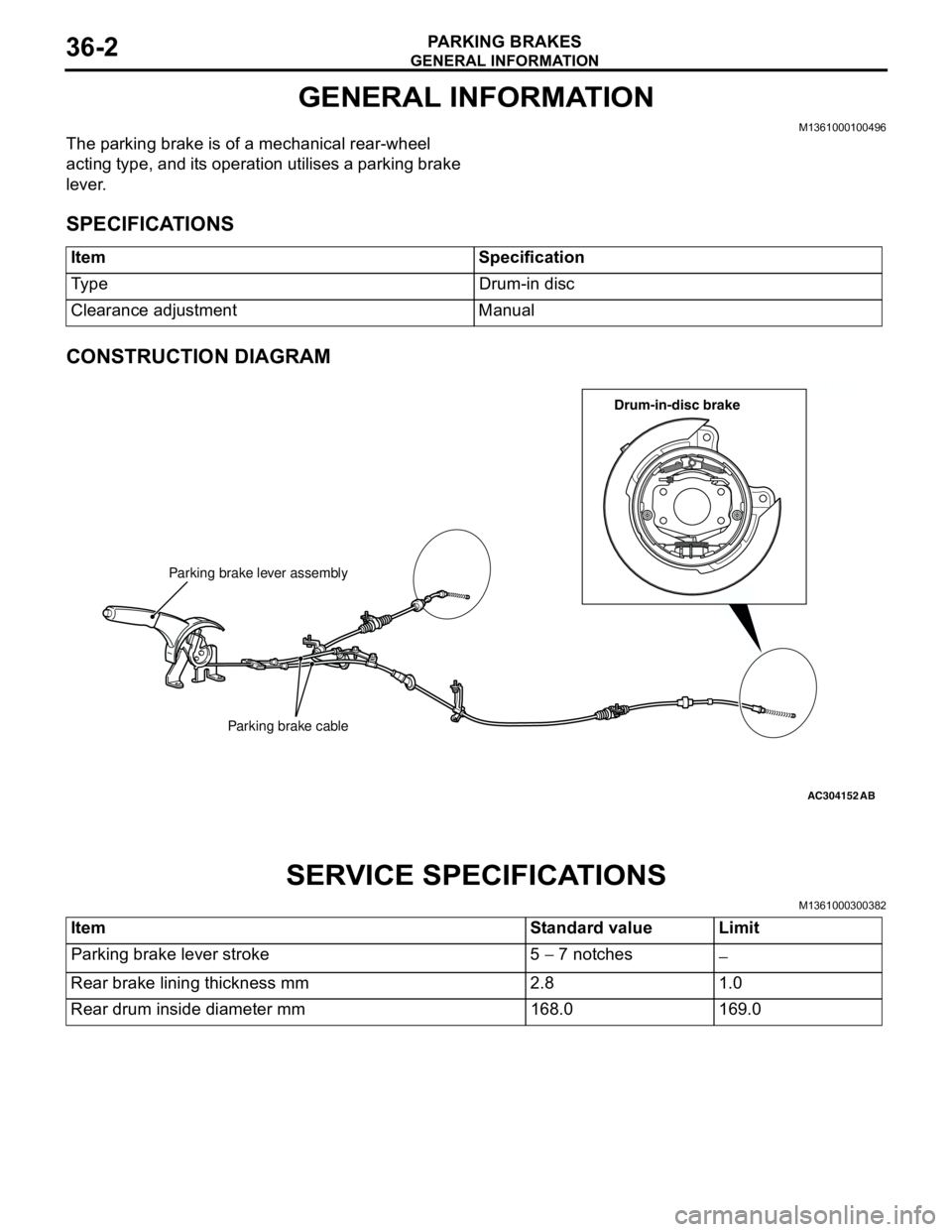
The parking brake is of a mechanical rear-wheel
acting type, and its operation utilises a parking brake
lever.
SPECIFICATIONS
CONSTRUCTION DIAGRAM
SERVICE SPECIFICATIONS
M1361000300382
Item Specification
Type Drum-in disc
Clearance adjustment Manual
AC211553
AC104333
AC304152
Parking brake lever assembly
Parking brake cable
AB
Drum-in-disc brake
Item Standard value Limit
Parking brake lever stroke 5 − 7 notches
−
Rear brake lining thickness mm 2.8 1.0
Rear drum inside diameter mm 168.0 169.0
Page 227 of 788
LUBRICANTS
PARKING BRAKES36-3
LUBRICANTS
M1361000400293
ON-VEHICLE SERVICE
PARKING BRAKE LEVER STROKE
CHECK AND ADJUSTMENT
M1361000900339
1. Pull the parking brake lever with a force of
approximately 200 N and count the number of
notches.
Standard value: 5 − 7 notches
2. If the parking brake lever stroke is not the
standard value, adjust as described below.
(1) Remove the rear console assembly (Refer to
GROUP 52A, Rear Floor Console P.52A-8).
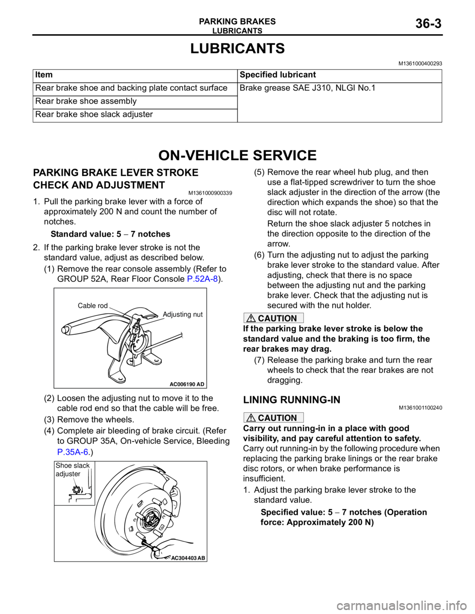
(2) Loosen the adjusting nut to move it to the
cable rod end so that the cable will be free.
(3) Remove the wheels.
(4) Complete air bleeding of brake circuit. (Refer
to GROUP 35A, On-vehicle Service, Bleeding
P.35A-6.)(5) Remove the rear wheel hub plug, and then
use a flat-tipped screwdriver to turn the shoe
slack adjuster in the direction of the arrow (the
direction which expands the shoe) so that the
disc will not rotate.
Return the shoe slack adjuster 5 notches in
the direction opposite to the direction of the
arrow.
(6) Turn the adjusting nut to adjust the parking
brake lever stroke to the standard value. After
adjusting, check that there is no space
between the adjusting nut and the parking
brake lever. Check that the adjusting nut is
secured with the nut holder.
CAUTION
If the parking brake lever stroke is below the
standard value and the braking is too firm, the
rear brakes may drag.
(7) Release the parking brake and turn the rear
wheels to check that the rear brakes are not
dragging.
LINING RUNNING-INM1361001100240
CAUTION
Carry out running-in in a place with good
visibility, and pay careful attention to safety.
Carry out running-in by the following procedure when
replacing the parking brake linings or the rear brake
disc rotors, or when brake performance is
insufficient.
1. Adjust the parking brake lever stroke to the
standard value.
Specified value: 5 − 7 notches (Operation
force: Approximately 200 N) Item Specified lubricant
Rear brake shoe and backing plate contact surface Brake grease SAE J310, NLGI No.1
Rear brake shoe assembly
Rear brake shoe slack adjuster
AC006190
Cable rod
Adjusting nut
AD
AC304403AB
Shoe slack
adjuster
Page 232 of 788
Page 233 of 788
PARKING BRAKE LINING AND DRUM
PARKING BRAKES36-9
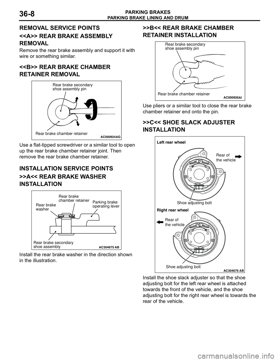
>>D<< SHOE RETURN SPRINGS
INSTALLATION
The shoe return springs are not interchangeable as
their constants are different. The one with blue paint
mark should be install at the front of the vehicle, and
the other with yellow paint at the rear of the vehicle,
respectively.
NOTE: The illustration shows the left rear wheel. The
right rear wheel is symmetrical to that.
INSPECTIONM1361002600248
PARKING BRAKE LINING AND DRUM
CHECK
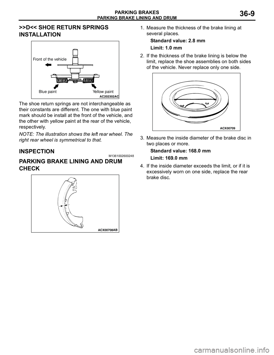
1. Measure the thickness of the brake lining at
several places.
Standard value: 2.8 mm
Limit: 1.0 mm
2. If the thickness of the brake lining is below the
limit, replace the shoe assemblies on both sides
of the vehicle. Never replace only one side.
3. Measure the inside diameter of the brake disc in
two places or more.
Standard value: 168.0 mm
Limit: 169.0 mm
4. If the inside diameter exceeds the limit, or if it is
excessively worn on one side, replace the rear
brake disc.
AC202302AC
Front of the vehicle
Blue paint Yellow paint
ACX00708AB
ACX00709
Page 235 of 788
37-1
GROUP 37
POWER STEERING
CONTENTS
GENERAL INFORMATION . . . . . . . .37-3
SERVICE SPECIFICATIONS . . . . . . .37-6
LUBRICANTS . . . . . . . . . . . . . . . . . .37-7
SEALANTS . . . . . . . . . . . . . . . . . . . .37-7
SPECIAL TOOLS . . . . . . . . . . . . . . . .37-8
ON-VEHICLE SERVICE . . . . . . . . . . .37-11
STEERING WHEEL FREE PLAY
CHECK . . . . . . . . . . . . . . . . . . . . . . . . . . . . 37-11
STEERING ANGLE CHECK . . . . . . . . . . . . 37-11
TIE ROD END BALL JOINT TURNING
TORQUE CHECK . . . . . . . . . . . . . . . . . . . . 37-12
STATIONARY STEERING EFFORT
CHECK . . . . . . . . . . . . . . . . . . . . . . . . . . . . 37-12
STEERING WHEEL RETURN TO
CENTRE CHECK . . . . . . . . . . . . . . . . . . . . 37-13DRIVE BELT TENSION CHECK . . . . . . . . . 37-13
FLUID LEVEL CHECK . . . . . . . . . . . . . . . . 37-13
FLUID REPLACEMENT . . . . . . . . . . . . . . . 37-13
POWER STEERING SYSTEM AIR
BLEEDING . . . . . . . . . . . . . . . . . . . . . . . . . 37-13
OIL PUMP PRESSURE TEST . . . . . . . . . . 37-14
POWER STEERING PRESSURE
SWITCH CHECK . . . . . . . . . . . . . . . . . . . . . 37-15
TIE ROD END BALL JOINT DUST COVER
CHECK . . . . . . . . . . . . . . . . . . . . . . . . . . . . 37-15
STEERING COLUMN SHAFT
ASSEMBLY SHOCK ABSORBING
MECHANISM CHECK . . . . . . . . . . . . . . . . . 37-15
STEERING WHEEL* . . . . . . . . . . . . . .37-17
REMOVAL AND INSTALLATION
REMOVAL AND INSTALLATION
Continued on next page
WARNINGS REGARDING SERVICING OF SUPPLEMENTAL RESTRAINT SYSTEM (SRS) EQUIPPED VEHICLES
WARNING
•Improper service or maintenance of any component of the SRS, or any SRS-related component, can lead to
personal injury or death to service personnel (from inadvertent firing of the air bag) or to the driver and
paassenger (from rendering the SRS inoperative).
•Service or maintenance of any SRS component or SRS-related component must be performed only at an
authorized MITSUBISHI dealer.
•MITSUBISHI dealer personnel must thoroughly review this manual, and especially its GROUP 52B - Supplemental
Restraint System (SRS) before beginning any service or maintenance of any component of the SRS or any
SRS-related component.
NOTE
The SRS includes the following components: SRS air bag control unit, SRS warning light, front impact sensors, air bag module,
clock spring, and interconnecting wiring. Other SRS-related components (that may have to be removed/installed in connection
with SRS service or maintenance) are indicated in the table of contents by an asterisk (*).
Page 237 of 788

GENERAL INFORMATION
POWER STEERING37-3
GENERAL INFORMATION
M1372000100337
Power steering has been adopted in all vehicles to
make the steering system easier to handle.
FEATURES
•A 4-spoke steering wheel is used.
•MOMO leather-wrapped 3-spoke steering wheel
is used.
•A steering column has a shock absorbing
mechanism and a tilt steering mechanism.•Integral-type rack and pinion gear with high
rigidity and excellent response is used.
•A vane type pump with a fluid flow rate control
system which change steering effort according to
the engine speed is used.
•The separate plastic resin oil reservoir is used to
reduce weight and to make the fluid level
checking easier.
SPECIFICATIONS
Item Comfort Sport
Steering
wheelType 4-spoke type MOMO leather-wrapped
3-spoke type
Outside diameter mm 380 365
Maximum number of turns 3.19 2.86
3.08
Steering
columnColumn mechanism Shock absorbing mechanism and Tilt steering mechanism
Power steering type Integral type
Oil pump Type Vane pump
Basic discharge amount cm
3/rev.7.2 <1300, 1600>
8.1 <2000>7.2 <1300, 1600>
8.1 <2000>
Relief pressure MPa 8.8 8.8
Reservoir type Separate type (plastic)
Pressure switch Equipped
Steering
gearType Rack and pinion
Stroke ratio (Rack stroke/Steering
wheel maximum turning radius)45.74 45.74
Rack stroke mm 146 131
141
Page 238 of 788
GENERAL INFORMATION
POWER STEERING37-4
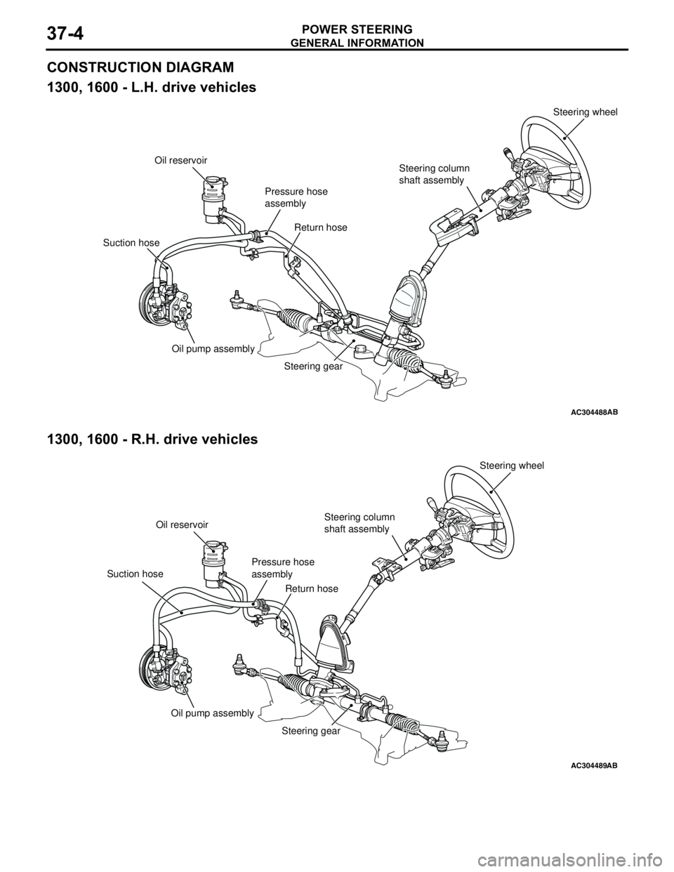
CONSTRUCTION DIAGRAM
1300, 1600 - L.H. drive vehicles
1300, 1600 - R.H. drive vehicles
AC304488AB
Steering wheel
Steering column
shaft assembly
Pressure hose
assembly Oil reservoir
Suction hoseReturn hose
Oil pump assembly
Steering gear
AC304489AB
Steering wheel
Steering column
shaft assembly
Pressure hose
assembly Oil reservoir
Suction hose
Return hose
Oil pump assembly
Steering gear