sensor MITSUBISHI LANCER 2005 Service Manual
[x] Cancel search | Manufacturer: MITSUBISHI, Model Year: 2005, Model line: LANCER, Model: MITSUBISHI LANCER 2005Pages: 788, PDF Size: 45.98 MB
Page 451 of 788
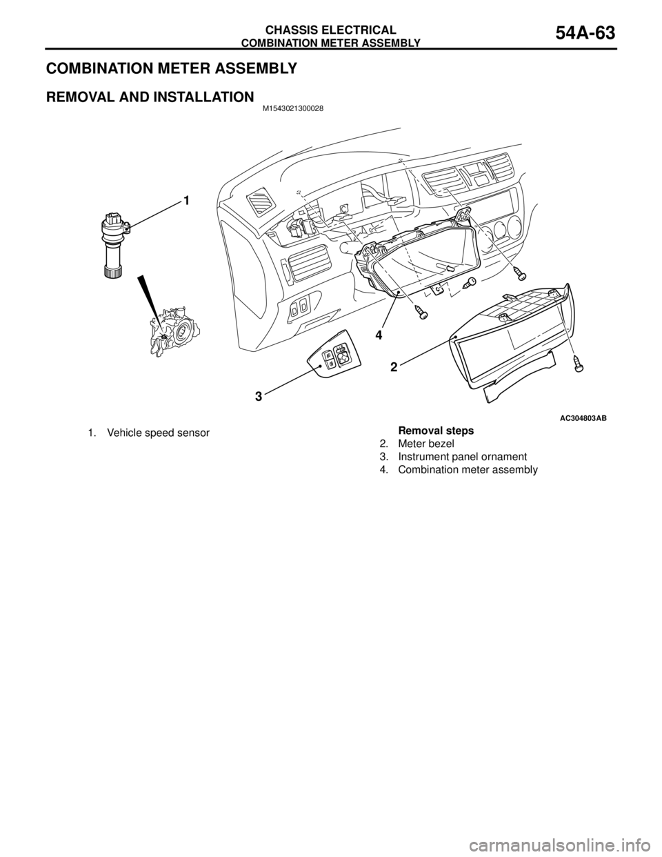
COMBINATION METER ASSEMBLY
CHASSIS ELECTRICAL54A-63
COMBINATION METER ASSEMBLY
REMOVAL AND INSTALLATIONM1543021300028
AC304803
4
32
AB
1
1. Vehicle speed sensorRemoval steps
2. Meter bezel
3. Instrument panel ornament
4. Combination meter assembly
Page 452 of 788
COMBINATION METER ASSEMBLY
CHASSIS ELECTRICAL54A-64
INSPECTIONM1543019502407
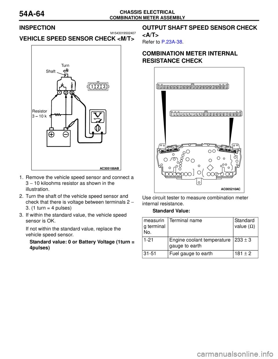
VEHICLE SPEED SENSOR CHECK
1. Remove the vehicle speed sensor and connect a
3 − 10 kiloohms resistor as shown in the
illustration.
2. Turn the shaft of the vehicle speed sensor and
check that there is voltage between terminals 2 −
3. (1 turn = 4 pulses)
3. If within the standard value, the vehicle speed
sensor is OK.
If not within the standard value, replace the
vehicle speed sensor.
Standard value: 0 or Battery Voltage (1turn =
4pulses)
OUTPUT SHAFT SPEED SENSOR CHECK
Refer to P.23A-38.
COMBINATION METER INTERNAL
RESISTANCE CHECK
Use circuit tester to measure combination meter
internal resistance.
Standard Value:
AC305188AB
Tu r n
Shaft
Resistor
3 – 10 k
measurin
g terminal
No.Terminal name Standard
value (Ω)
1-21 Engine coolant temperature
gauge to earth233 ± 3
31-51 Fuel gauge to earth 181 ± 2
AC005210AC
Page 495 of 788
TROUBLESHOOTING
HEATER, AIR CONDITIONER AND VENTILATION55-11
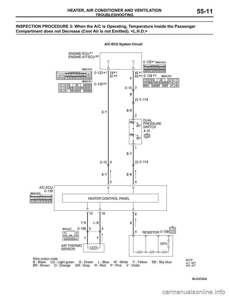
INSPECTION PROCEDURE 3: When the A/C is Operating, Temperature Inside the Passenger
Compartment does not Decrease (Cool Air is not Emitted).
ENGINE-ECU
A/C-ECUDUAL
PRESSURE
SWITCH
RESISTOR ENGINE-A/T-ECU
HEATER CONTROL PANEL
Wire colour code
B : Black LG : Light green G : Green L : Blue W : White Y : Yellow SB : Sky blue
BR : Brown O : Orange GR : Gray R : Red P : Pink V : Violet
AIR THERMO
SENSOR
NOTEM/T
A/T
A/C-ECU System Circuit
Page 496 of 788
TROUBLESHOOTING
HEATER, AIR CONDITIONER AND VENTILATION55-12
COMMENTS ON TROUBLE SYMPTOM
If cool air is not distributed when the A/C switch is on,
the air thermo sensor or the A/C compressor relay
system may be defective.
TROUBLESHOOTING HINTS
•Improper amount of refrigerant
•Malfunction of the air thermo sensor
•Malfunction of the dual pressure switch
•Malfunction of the A/C compressor relay
•Malfunction of the A/C refrigerant temperature
switch
•Malfunction of the magnetic clutch
•Malfunction of the manual air conditioner control
panel (A/C-ECU)
•Damaged the wiring harness or connectors
•Malfunction of the engine-ECU
engine-A/T-ECU
DIAGNOSIS
STEP 1. Check the defogger and outside/inside
air selection damper control motor operation.
Q: Do the defogger and outside/inside air selection
damper control motor work normally?
YES :
Go to Step 2.
NO : Refer to Inspection procedure 9
"Malfunction of the A/C-ECU power supply
system
STEP 2. Check the blower motor operation.
Q: Does the blower motor work normally?
YES :
Go to Step 3.
NO : Refer to Inspection procedure 5 "Blower fan
and motor do not turn P.55-29."
STEP 3. Check the A/C compressor.
Check the A/C compressor for compressor oil leaks.
Q: Is the check result satisfactory?
YES :
Go to Step 4.
NO : Replace the A/C compressor or the
expansion valve.
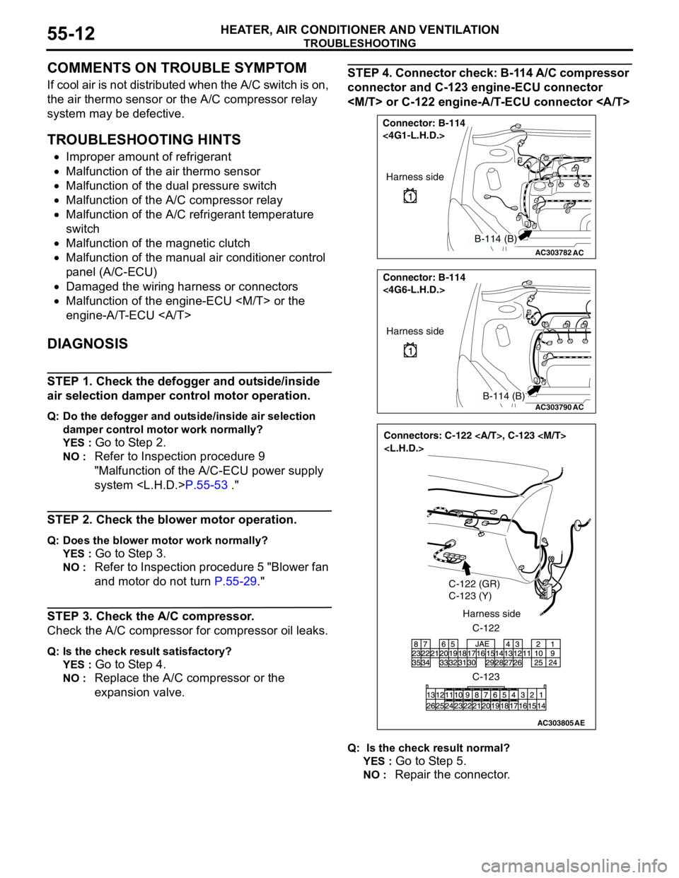
STEP 4. Connector check: B-114 A/C compressor
connector and C-123 engine-ECU connector
Q: Is the check result normal?
YES :
Go to Step 5.
NO : Repair the connector.
AC303782
Connector: B-114
<4G1-L.H.D.>
AC
Harness side
B-114 (B)
AC303790
Connector: B-114
<4G6-L.H.D.>
AC
Harness side
B-114 (B)
AC303805
Connectors: C-122 , C-123
C-122 (GR)
C-123 (Y)
C-122 Harness side
C-123
AE
Page 499 of 788
TROUBLESHOOTING
HEATER, AIR CONDITIONER AND VENTILATION55-15
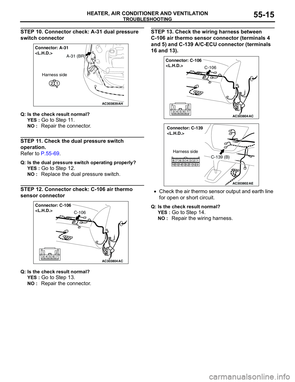
STEP 10. Connector check: A-31 dual pressure
switch connector
Q: Is the check result normal?
YES :
Go to Step 11.
NO : Repair the connector.
STEP 11. Check the dual pressure switch
operation.
Refer to P.55-69.
Q: Is the dual pressure switch operating properly?
YES :
Go to Step 12.
NO : Replace the dual pressure switch.
STEP 12. Connector check: C-106 air thermo
sensor connector
Q: Is the check result normal?
YES :
Go to Step 13.
NO : Repair the connector.
STEP 13. Check the wiring harness between
C-106 air thermo sensor connector (terminals 4
and 5) and C-139 A/C-ECU connector (terminals
16 and 13).
•Check the air thermo sensor output and earth line
for open or short circuit.
Q: Is the check result normal?
YES :
Go to Step 14.
NO : Repair the wiring harness.
AC303839
Connector: A-31
AH
Harness side
A-31 (BR)
AC303804
Connector: C-106
AC
C-106
AC303804
Connector: C-106
AC
C-106
AC303802
Connector: C-139
AE
C-139 (B)
Harness side
Page 503 of 788
TROUBLESHOOTING
HEATER, AIR CONDITIONER AND VENTILATION55-19
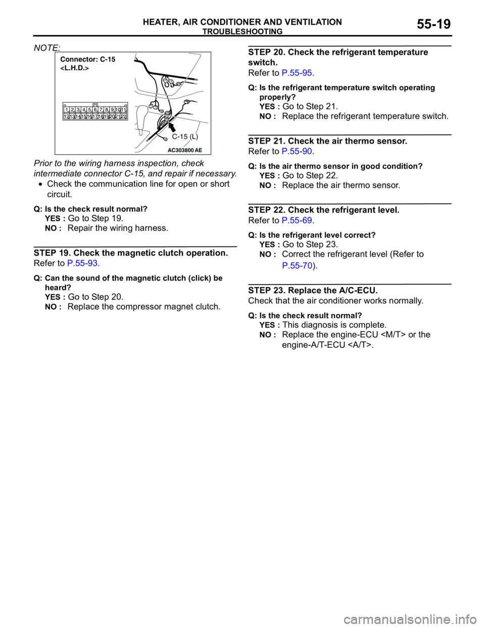
NOTE:
Prior to the wiring harness inspection, check
intermediate connector C-15, and repair if necessary.
•Check the communication line for open or short
circuit.
Q: Is the check result normal?
YES :
Go to Step 19.
NO : Repair the wiring harness.
STEP 19. Check the magnetic clutch operation.
Refer to P.55-93.
Q: Can the sound of the magnetic clutch (click) be
heard?
YES :
Go to Step 20.
NO : Replace the compressor magnet clutch.
STEP 20. Check the refrigerant temperature
switch.
Refer to P.55-95.
Q: Is the refrigerant temperature switch operating
properly?
YES :
Go to Step 21.
NO : Replace the refrigerant temperature switch.
STEP 21. Check the air thermo sensor.
Refer to P.55-90.
Q: Is the air thermo sensor in good condition?
YES :
Go to Step 22.
NO : Replace the air thermo sensor.
STEP 22. Check the refrigerant level.
Refer to P.55-69.
Q: Is the refrigerant level correct?
YES :
Go to Step 23.
NO : Correct the refrigerant level (Refer to
P.55-70).
STEP 23. Replace the A/C-ECU.
Check that the air conditioner works normally.
Q: Is the check result normal?
YES :
This diagnosis is complete.
NO : Replace the engine-ECU
engine-A/T-ECU .
AC303800
Connector: C-15
AE
C-15 (L)
Page 504 of 788
TROUBLESHOOTING
HEATER, AIR CONDITIONER AND VENTILATION55-20
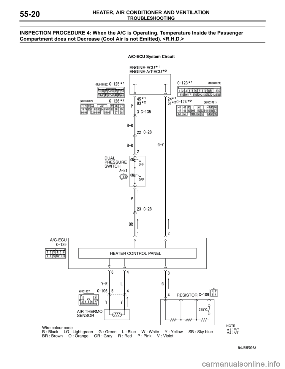
INSPECTION PROCEDURE 4: When the A/C is Operating, Temperature Inside the Passenger
Compartment does not Decrease (Cool Air is not Emitted).
ENGINE-ECU
A/C-ECUDUAL
PRESSURE
SWITCH
RESISTOR ENGINE-A/T-ECU
HEATER CONTROL PANEL
Wire colour code
B : Black LG : Light green G : Green L : Blue W : White Y : Yellow SB : Sky blue
BR : Brown O : Orange GR : Gray R : Red P : Pink V : Violet
AIR THERMO
SENSOR
NOTEM/T
A/T
A/C-ECU System Circuit
Page 505 of 788
TROUBLESHOOTING
HEATER, AIR CONDITIONER AND VENTILATION55-21
COMMENTS ON TROUBLE SYMPTOM
If cool air is not distributed when the A/C switch is on,
the air thermo sensor or the A/C compressor relay
system may be defective.
TROUBLESHOOTING HINTS
•Improper amount of refrigerant
•Malfunction of the air thermo sensor
•Malfunction of the dual pressure switch
•Malfunction of the A/C compressor relay
•Malfunction of the A/C refrigerant temperature
switch
•Malfunction of the magnetic clutch
•Malfunction of the manual air conditioner control
panel (A/C-ECU)
•Damaged the wiring harness or connectors
•Malfunction of the engine-ECU
engine-A/T-ECU
DIAGNOSIS
STEP 1. Check the defogger and outside/inside
air selection damper control motor operation.
Q: Do the defogger and outside/inside air selection
damper control motor work normally?
YES :
Go to Step 2.
NO : Refer to Inspection procedure 10
"Malfunction of the A/C-ECU power supply
system
STEP 2. Check the blower motor operation.
Q: Does the blower motor work normally?
YES :
Go to Step 3.
NO : Refer to Inspection procedure 5 "Blower fan
and motor do not turn P.55-29."
STEP 3. Check the A/C compressor.
Check the A/C compressor for compressor oil leaks.
Q: Is the check result satisfactory?
YES :
Go to Step 4.
NO : Replace the A/C compressor or the
expansion valve.
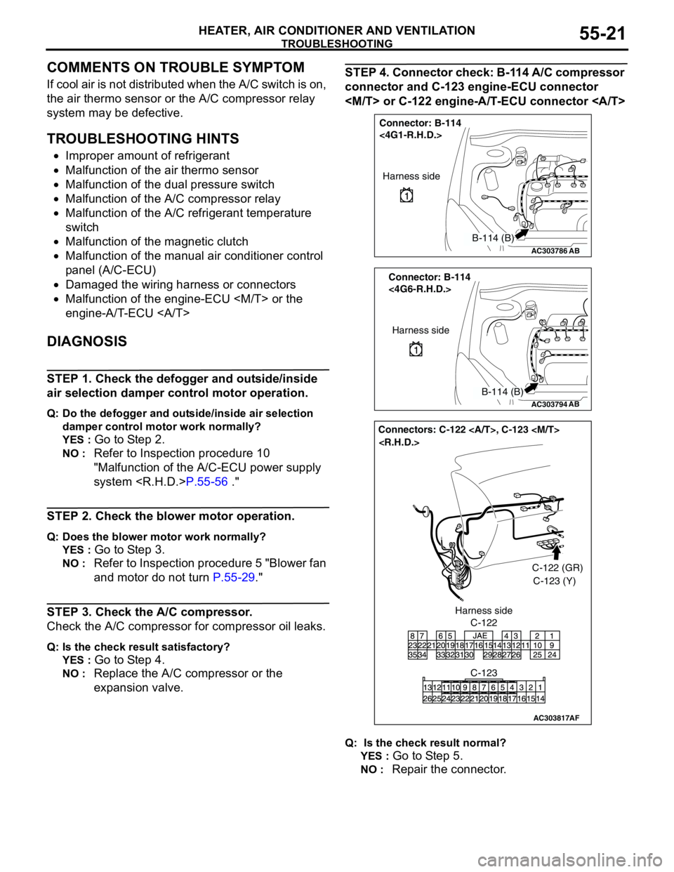
STEP 4. Connector check: B-114 A/C compressor
connector and C-123 engine-ECU connector
Q: Is the check result normal?
YES :
Go to Step 5.
NO : Repair the connector.
AC303786
Connector: B-114
<4G1-R.H.D.>
AB
Harness side
B-114 (B)
AC303794
Connector: B-114
<4G6-R.H.D.>
AB
Harness side
B-114 (B)
AC303817
Connectors: C-122 , C-123
AF
C-122C-122 (GR)
C-123 (Y)
C-123 Harness side
Page 508 of 788
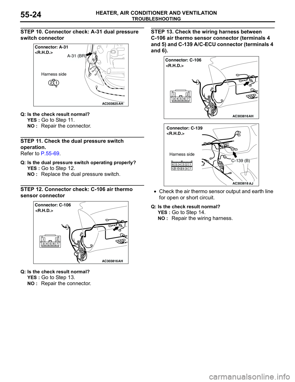
TROUBLESHOOTING
HEATER, AIR CONDITIONER AND VENTILATION55-24
STEP 10. Connector check: A-31 dual pressure
switch connector
Q: Is the check result normal?
YES :
Go to Step 11.
NO : Repair the connector.
STEP 11. Check the dual pressure switch
operation.
Refer to P.55-69.
Q: Is the dual pressure switch operating properly?
YES :
Go to Step 12.
NO : Replace the dual pressure switch.
STEP 12. Connector check: C-106 air thermo
sensor connector
Q: Is the check result normal?
YES :
Go to Step 13.
NO : Repair the connector.
STEP 13. Check the wiring harness between
C-106 air thermo sensor connector (terminals 4
and 5) and C-139 A/C-ECU connector (terminals 4
and 6).
•Check the air thermo sensor output and earth line
for open or short circuit.
Q: Is the check result normal?
YES :
Go to Step 14.
NO : Repair the wiring harness.
AC303825
Connector: A-31
AH
A-31 (BR)
Harness side
AC303816
Connector: C-106
AH
AC303816
Connector: C-106
AH
AC303818
Connector: C-139
AJ
Harness side
C-139 (B)
11 12657 8 9 103 421
Page 512 of 788

TROUBLESHOOTING
HEATER, AIR CONDITIONER AND VENTILATION55-28
STEP 19. Check the magnetic clutch operation.
Refer to P.55-93.
Q: Can the sound of the magnetic clutch (click) be
heard?
YES :
Go to Step 20.
NO : Replace the compressor magnet clutch.
STEP 20. Check the refrigerant temperature
switch.
Refer to P.55-95.
Q: Is the refrigerant temperature switch operating
properly?
YES :
Go to Step 21.
NO : Replace the refrigerant temperature switch.
STEP 21. Check the air thermo sensor.
Refer to P.55-90.
Q: Is the air thermo sensor in good condition?
YES :
Go to Step 22.
NO : Replace the air thermo sensor.
STEP 22. Check the refrigerant level.
Refer to P.55-69.
Q: Is the refrigerant level correct?
YES :
Go to Step 23.
NO : Correct the refrigerant level (Refer to
On-vehicle Service P.55-70).
STEP 23. Replace the A/C-ECU.
Check that the air conditioner works normally.
Q: Is the check result normal?
YES :
This diagnosis is complete.
NO : Replace the engine-ECU
engine-A/T-ECU .