sensor MITSUBISHI LANCER 2005 Owner's Manual
[x] Cancel search | Manufacturer: MITSUBISHI, Model Year: 2005, Model line: LANCER, Model: MITSUBISHI LANCER 2005Pages: 788, PDF Size: 45.98 MB
Page 106 of 788
IGNITION SYSTEM
ENGINE ELECTRICAL16-42
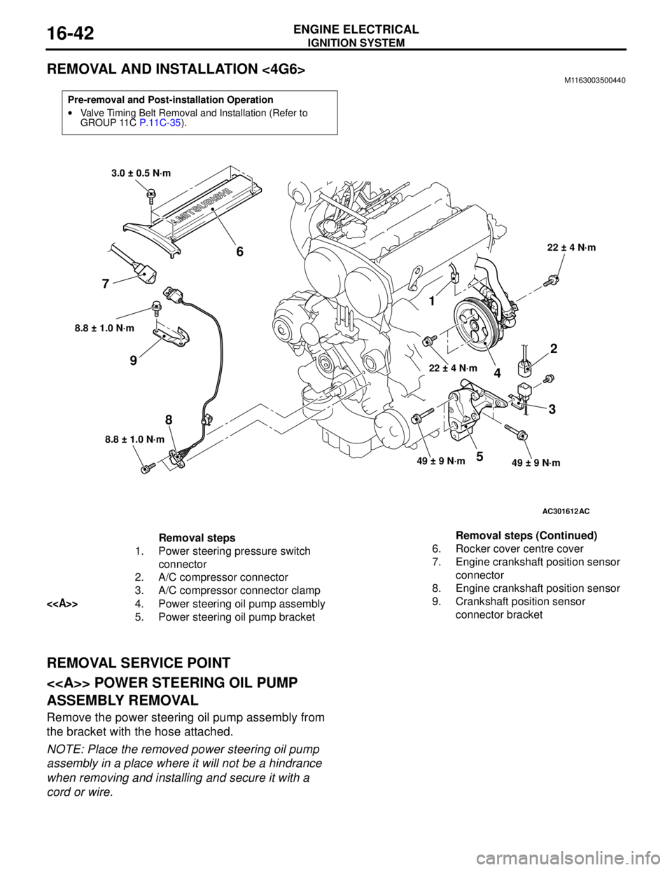
REMOVAL AND INSTALLATION <4G6>M1163003500440
REMOVAL SERVICE POINT
<> POWER STEERING OIL PUMP
ASSEMBLY REMOVAL
Remove the power steering oil pump assembly from
the bracket with the hose attached.
NOTE: Place the removed power steering oil pump
assembly in a place where it will not be a hindrance
when removing and installing and secure it with a
cord or wire.
Pre-removal and Post-installation Operation
•Valve Timing Belt Removal and Installation (Refer to
GROUP 11C P.11C-35).
AC301612
8.8 ± 1.0 N·m
8
8.8 ± 1.0 N·m
9
1
22 ± 4 N·m
4
2
3
49 ± 9 N·m49 ± 9 N·m5
22 ± 4 N·m
3.0 ± 0.5 N·m
6
7
AC
Removal steps
1. Power steering pressure switch
connector
2. A/C compressor connector
3. A/C compressor connector clamp
<>4. Power steering oil pump assembly
5. Power steering oil pump bracket6. Rocker cover centre cover
7. Engine crankshaft position sensor
connector
8. Engine crankshaft position sensor
9. Crankshaft position sensor
connector bracket Removal steps (Continued)
Page 107 of 788
IGNITION SYSTEM
ENGINE ELECTRICAL16-43
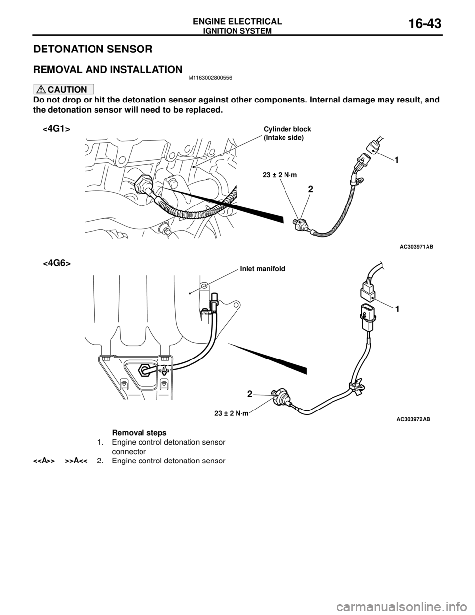
DETONATION SENSOR
REMOVAL AND INSTALLATIONM1163002800556
CAUTION
Do not drop or hit the detonation sensor against other components. Internal damage may result, and
the detonation sensor will need to be replaced.
AC303971
21
23 ± 2 N·m
AB
<4G1>Cylinder block
(Intake side)
AC303972
21
23 ± 2 N·mAB
<4G6>Inlet manifold
Removal steps
1. Engine control detonation sensor
connector
<> >>A<<2. Engine control detonation sensor
Page 108 of 788
IGNITION SYSTEM
ENGINE ELECTRICAL16-44
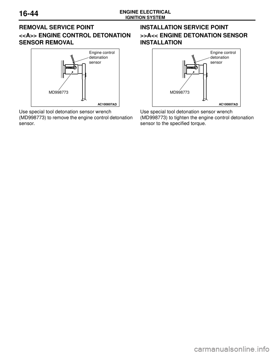
REMOVAL SERVICE POINT
<> ENGINE CONTROL DETONATION
SENSOR REMOVAL
Use special tool detonation sensor wrench
(MD998773) to remove the engine control detonation
sensor.
INSTALLATION SERVICE POINT
>>A<< ENGINE DETONATION SENSOR
INSTALLATION
Use special tool detonation sensor wrench
(MD998773) to tighten the engine control detonation
sensor to the specified torque.
AC100807
MD998773Engine control
detonation
sensor
ADAC100807
MD998773Engine control
detonation
sensor
AD
Page 113 of 788

EMISSION CONTROL
ENGINE AND EMISSION CONTROL17-5
EMISSION CONTROL
GENERAL INFORMATIONM1173000100370
The emission control system consists of the following
subsystems:•Crankcase emission control system
•Evaporative emission control system
•Exhaust emission control system
EMISSION CONTROL DEVICE
REFERENCE TABLE
M1173006600135
SERVICE SPECIFICATION(S)M1173000300288
Items Name Specification
Crankcase emission control
systemPositive crankcase ventilation
(PCV) valveVariable flow type
(Purpose: HC reduction)
Evaporative emission control
systemCanister
Purge control solenoid valveEquipped
Duty cycle type solenoid valve
(Purpose: HC reduction)
Exhaust emission control system Air-fuel ratio control device - MPI
systemOxygen sensor feedback type
(Purpose: CO, HC, NOx reduction)
Exhaust gas recirculation system
•EGR valve
•EGR control solenoid valveEquipped
Single type
Duty cycle type solenoid valve
(Purpose: NOx reduction)
Catalytic converter Monolith type
(Purpose: CO, HC, NOx reduction)
Related parts Crankcase
emission
control
systemEvaporative
emission
control
systemAir/fuel ratio
control
systemCatalytic
converterExhaust gas
recirculation
system
PCV valve
×
Purge control solenoid valve
×
MPI system component
××
Catalytic converter
×
EGR valve
×
EGR control solenoid valve
×
Items Standard value
Purge control solenoid valve coil resistance (at 20°C) Ω30 − 34
EGR control solenoid valve coil resistance (at 20°C) Ω29 − 35
Page 114 of 788
EMISSION CONTROL
ENGINE AND EMISSION CONTROL17-6
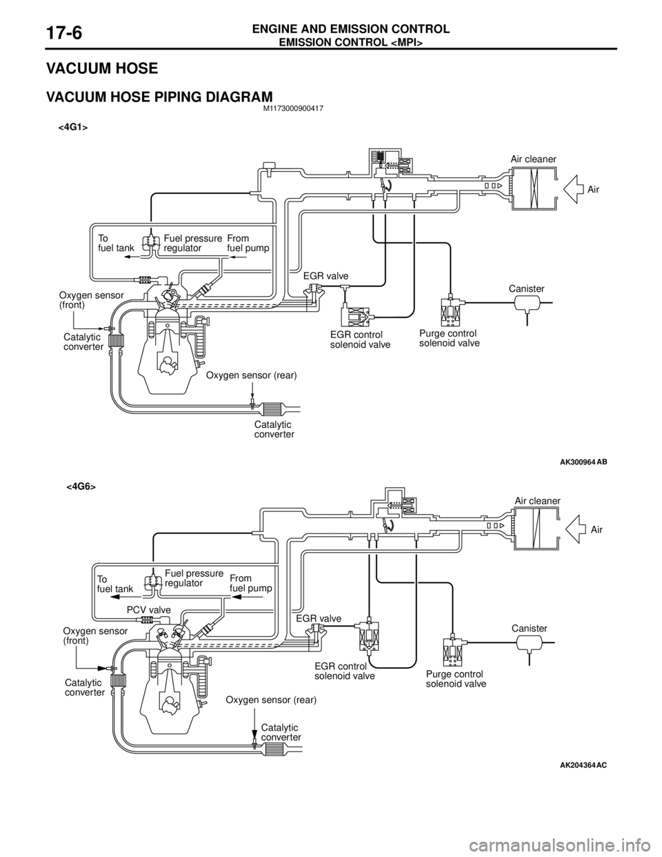
VACUUM HOSE
VACUUM HOSE PIPING DIAGRAMM1173000900417
AK300964
To
fuel tankFuel pressure
regulatorFrom
fuel pump
Catalytic
converter
Catalytic
converter Oxygen sensor
(front)
Oxygen sensor (rear)EGR valve <4G1>
EGR control
solenoid valvePurge control
solenoid valveCanisterAir
AB
Air cleaner
AK204364
AC
Air cleaner
Air
Canister
Purge control
solenoid valve EGR control
solenoid valve EGR valve From
fuel pump To
fuel tankFuel pressure
regulator
PCV valve
Oxygen sensor
(front)
Oxygen sensor (rear) Catalytic
converter
Catalytic
converter
<4G6>
Page 118 of 788
EMISSION CONTROL
ENGINE AND EMISSION CONTROL17-10
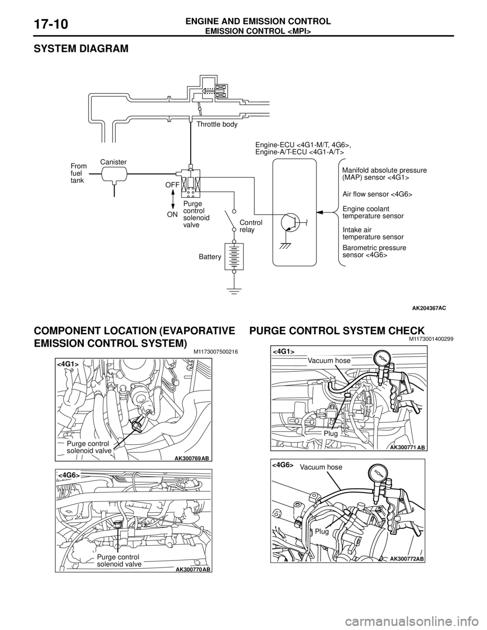
SYSTEM DIAGRAM
COMPONENT LOCATION (EVAPORATIVE
EMISSION CONTROL SYSTEM)
M1173007500216
PURGE CONTROL SYSTEM CHECKM1173001400299
AK204367AC
Throttle body
Canister
From
fuel
tank
OFF
ONPurge
control
solenoid
valveControl
relay
BatteryEngine-ECU <4G1-M/T, 4G6>,
Engine-A/T-ECU <4G1-A/T>
Air flow sensor <4G6>
Engine coolant
temperature sensor
Intake air
temperature sensor
Barometric pressure
sensor <4G6> Manifold absolute pressure
(MAP) sensor <4G1>
AK300769
<4G1>
AB
Purge control
solenoid valve
AK300770
<4G6>
AB
Purge control
solenoid valve
AK300771
<4G1>
AB
Plug
Vacuum hose
AK300772
<4G6>
AB
Plug
Vacuum hose
Page 121 of 788
EMISSION CONTROL
ENGINE AND EMISSION CONTROL17-13
EXHAUST GAS RECIRCULATION
(EGR) SYSTEM
GENERAL INFORMATION (EGR SYSTEM)M1173005200327
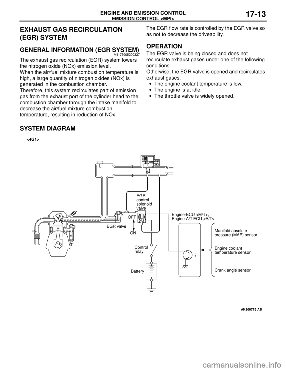
The exhaust gas recirculation (EGR) system lowers
the nitrogen oxide (NOx) emission level.
When the air/fuel mixture combustion temperature is
high, a large quantity of nitrogen oxides (NOx) is
generated in the combustion chamber.
Therefore, this system recirculates part of emission
gas from the exhaust port of the cylinder head to the
combustion chamber through the intake manifold to
decrease the air/fuel mixture combustion
temperature, resulting in reduction of NOx.The EGR flow rate is controlled by the EGR valve so
as not to decrease the driveability.
OPERATION
The EGR valve is being closed and does not
recirculate exhaust gases under one of the following
conditions.
Otherwise, the EGR valve is opened and recirculates
exhaust gases.
•The engine coolant temperature is low.
•The engine is at idle.
•The throttle valve is widely opened.
SYSTEM DIAGRAM
AK300775
Manifold absolute
pressure (MAP) sensor Engine-ECU
Engine-A/T-ECU
Engine coolant
temperature sensor
Crank angle sensor EGR
control
solenoid
valve
EGR valveOFF
ON
Control
relay
Battery
AB
<4G1>
Page 122 of 788
EMISSION CONTROL
ENGINE AND EMISSION CONTROL17-14
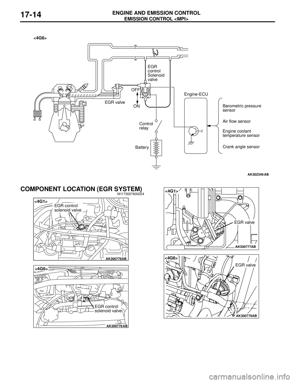
COMPONENT LOCATION (EGR SYSTEM)M1173007600224
AK302349AB
<4G6>
EGR
control
Solenoid
valve
EGR valveOFF
ON
Control
relay
BatteryEngine-ECU
Barometric pressure
sensor
Air flow sensor
Engine coolant
temperature sensor
Crank angle sensor
AK300776
<4G1>
AB
EGR control
solenoid valve
AK300778
<4G6>
AB
EGR control
solenoid valve
AK300777
<4G1>
AB
EGR valve
AK300779AB
<4G6>
EGR valve
Page 140 of 788
FRONT AXLE HUB ASSEMBLY
FRONT AXLE26-8
FRONT AXLE HUB ASSEMBLY
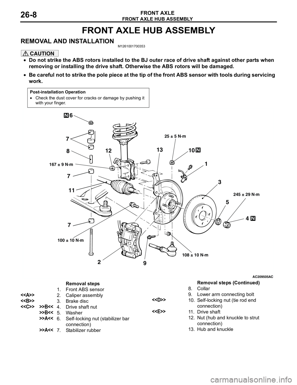
REMOVAL AND INSTALLATIONM1261001700353
CAUTION
•Do not strike the ABS rotors installed to the BJ outer race of drive shaft against other parts when
removing or installing the drive shaft. Otherwise the ABS rotors will be damaged.
•Be careful not to strike the pole piece at the tip of the front ABS sensor with tools during servicing
work.
Post-installation Operation
•Check the dust cover for cracks or damage by pushing it
with your finger.
AC209505
N
N
N
5
4 3 1 810
9 2 76
167 ± 9 N·m25 ± 5 N·m
108 ± 10 N·m245 ± 29 N·m
100 ± 10 N·m
AC
7
7
111213
Removal steps
1. Front ABS sensor
<>
2. Caliper assembly
<>
3. Brake disc
<
>>B<<5. Washer
>>A<<6. Self-locking nut (stabilizer bar
connection)
>>A<<7. Stabilizer rubber8. Collar
9. Lower arm connecting bolt
<
10. Self-locking nut (tie rod end
connection)
<
11 . D r i v e s h a f t
12. Nut (hub and knuckle to strut
connection)
13. Hub and knuckle
Removal steps (Continued)
Page 146 of 788
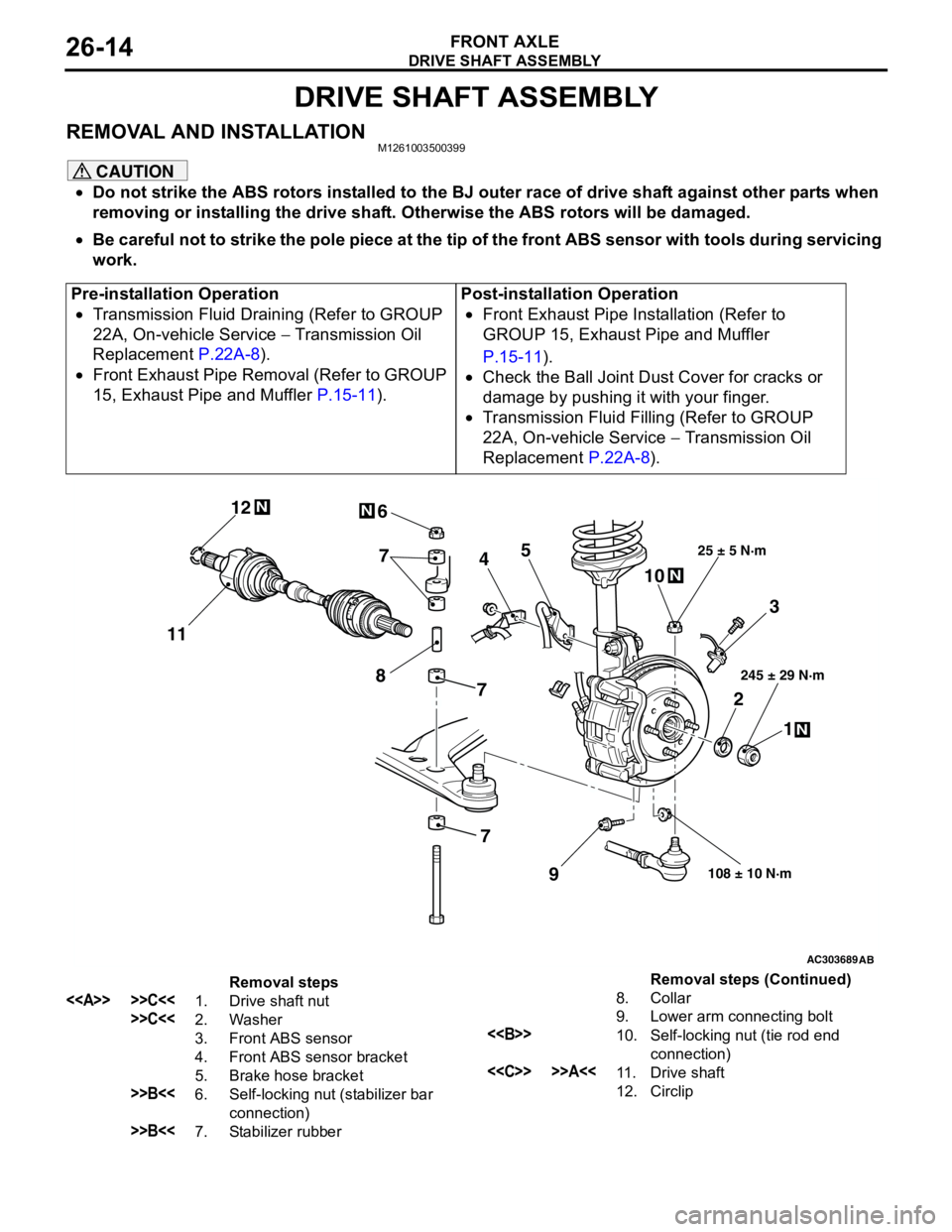
DRIVE SHAFT ASSEMBLY
FRONT AXLE26-14
DRIVE SHAFT ASSEMBLY
REMOVAL AND INSTALLATIONM1261003500399
CAUTION
•Do not strike the ABS rotors installed to the BJ outer race of drive shaft against other parts when
removing or installing the drive shaft. Otherwise the ABS rotors will be damaged.
•Be careful not to strike the pole piece at the tip of the front ABS sensor with tools during servicing
work.
Pre-installation Operation
•Transmission Fluid Draining (Refer to GROUP
22A, On-vehicle Service − Transmission Oil
Replacement P.22A-8).
•Front Exhaust Pipe Removal (Refer to GROUP
15, Exhaust Pipe and Muffler P.15-11).Post-installation Operation
•Front Exhaust Pipe Installation (Refer to
GROUP 15, Exhaust Pipe and Muffler
P.15-11).
•Check the Ball Joint Dust Cover for cracks or
damage by pushing it with your finger.
•Transmission Fluid Filling (Refer to GROUP
22A, On-vehicle Service − Transmission Oil
Replacement P.22A-8).
AC303689AB
9
N
N
NN
10 7
4
3
2
1
25 ± 5 N·m
245 ± 29 N·m
108 ± 10 N·m
8
5 6
1112
7
7
Removal steps
<> >>C<<1. Drive shaft nut
>>C<<2. Washer
3. Front ABS sensor
4. Front ABS sensor bracket
5. Brake hose bracket
>>B<<6. Self-locking nut (stabilizer bar
connection)
>>B<<7. Stabilizer rubber8. Collar
9. Lower arm connecting bolt
<>10. Self-locking nut (tie rod end
connection)
<
12. CirclipRemoval steps (Continued)