window MITSUBISHI LANCER 2005 Repair Manual
[x] Cancel search | Manufacturer: MITSUBISHI, Model Year: 2005, Model line: LANCER, Model: MITSUBISHI LANCER 2005Pages: 788, PDF Size: 45.98 MB
Page 557 of 788
ON-VEHICLE SERVICE
HEATER, AIR CONDITIONER AND VENTILATION55-73
PERFORMANCE TEST M1552001400355
1. The vehicles to be tested should be in a place that
is not in direct sunlight.
2. Close the high and low-pressure valve of the
gauge manifold.
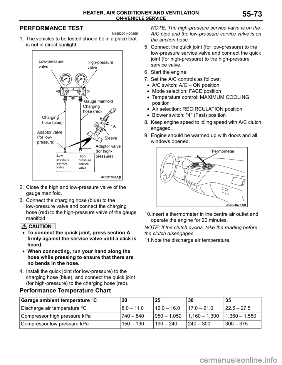
3. Connect the charging hose (blue) to the
low-pressure valve and connect the charging
hose (red) to the high-pressure valve of the gauge
manifold.
CAUTION
•To connect the quick joint, press section A
firmly against the service valve until a click is
heard.
•When connecting, run your hand along the
hose while pressing to ensure that there are
no bends in the hose.
4. Install the quick joint (for low-pressure) to the
charging hose (blue), and connect the quick joint
(for high-pressure) to the charging hose (red).NOTE: The high-pressure service valve is on the
A/C pipe and the low-pressure service valve is on
the suction hose.
5. Connect the quick joint (for low-pressure) to the
low-pressure service valve and connect the quick
joint (for high-pressure) to the high-pressure
service valve.
6. Start the engine.
7. Set the A/C controls as follows:
•A/C switch: A/C − ON position
•Mode selection: FACE position
•Temperature control: MAXIMUM COOLING
position
•Air selection: RECIRCULATION position
•Blower switch: "4" (Fast) position
8. Keep engine speed to idling speed with A/C clutch
engaged.
9. Engine should be warmed up with doors and all
windows opened.
10.Insert a thermometer in the centre air outlet and
operate the engine for 20 minutes.
NOTE: If the clutch cycles, take the reading before
the clutch disengages.
11.Note the discharge air temperature.
Performance Temperature Chart
AC001388
Low-pressure
valveHigh-pressure
valve
Gauge manifold
Charging
hose (red)
A
Sleeve Charging
hose (blue)
Adaptor valve
(for low-
pressure)
Low-
pressure
service
valveHigh-
pressure
service
valve
AB
Adaptor valve
(for high-
pressure)
AC304576
Thermometer
AB
Garage ambient temperature °C20 25 30 35
Discharge air temperature °C8.0 − 11.0 12.0 − 16.0 17.0 − 21.0 22.5 − 27.5
Compressor high pressure kPa 740 − 840 950 − 1,050 1,160 − 1,300 1,360 − 1,550
Compressor low pressure kPa 150 − 190 190 − 240 240 − 300 300 − 375
Page 563 of 788
HEATER CONTROL ASSEMBLY AND A/C SWITCH
HEATER, AIR CONDITIONER AND VENTILATION55-79
INSPECTIONM1552014300927
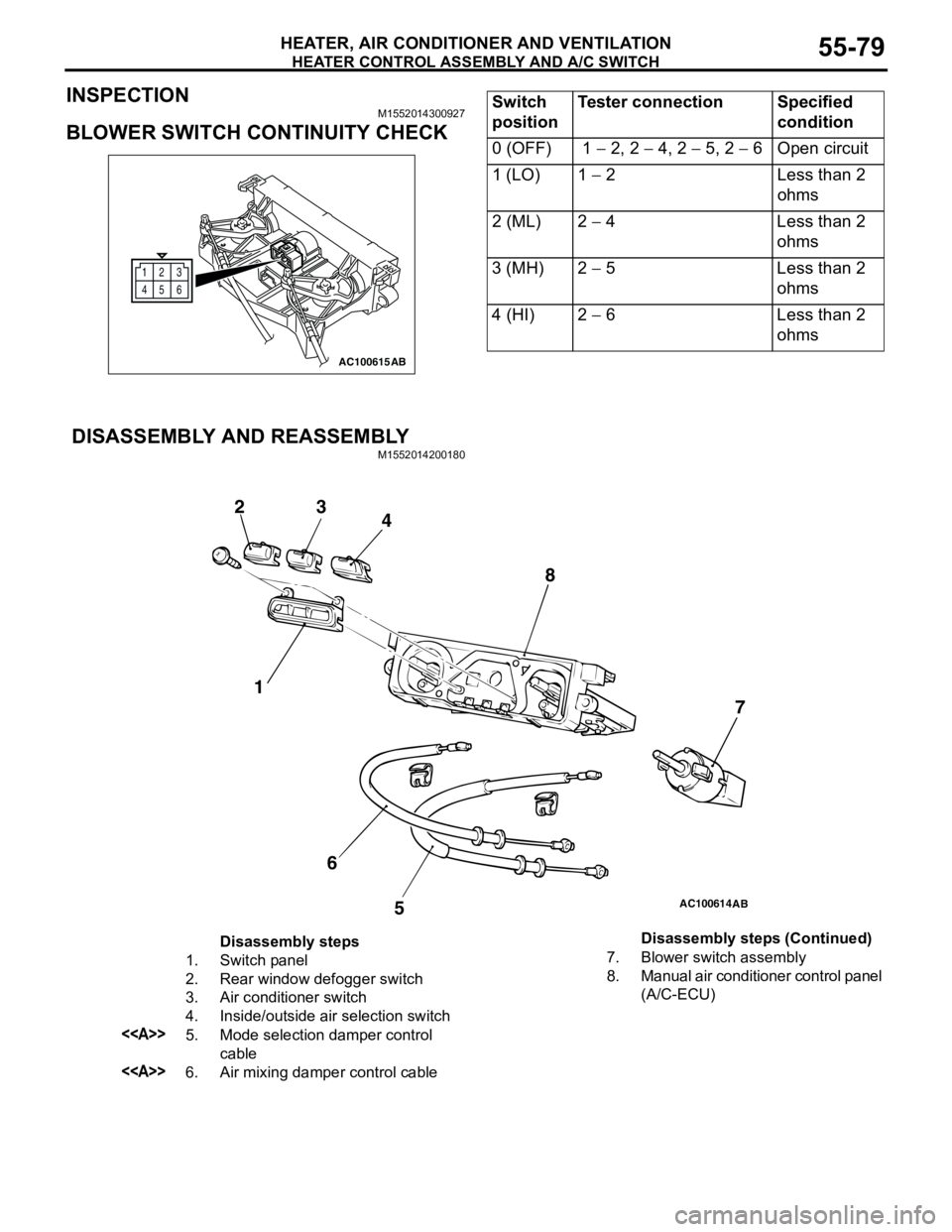
BLOWER SWITCH CONTINUITY CHECK
DISASSEMBLY AND REASSEMBLY
M1552014200180
12
6 3
45
AC100615AB
Switch
positionTester connection Specified
condition
0 (OFF) 1 − 2, 2 − 4, 2 − 5, 2 − 6 Open circuit
1 (LO) 1 − 2 Less than 2
ohms
2 (ML) 2 − 4 Less than 2
ohms
3 (MH) 2 − 5 Less than 2
ohms
4 (HI) 2 − 6 Less than 2
ohms
AC100614
1 23
4
5 67 8
AB
Disassembly steps
1. Switch panel
2. Rear window defogger switch
3. Air conditioner switch
4. Inside/outside air selection switch
<>5. Mode selection damper control
cable
<>6. Air mixing damper control cable7. Blower switch assembly
8. Manual air conditioner control panel
(A/C-ECU) Disassembly steps (Continued)
Page 588 of 788
ECU
COMPONENT LOCATIONS70-2
ECU
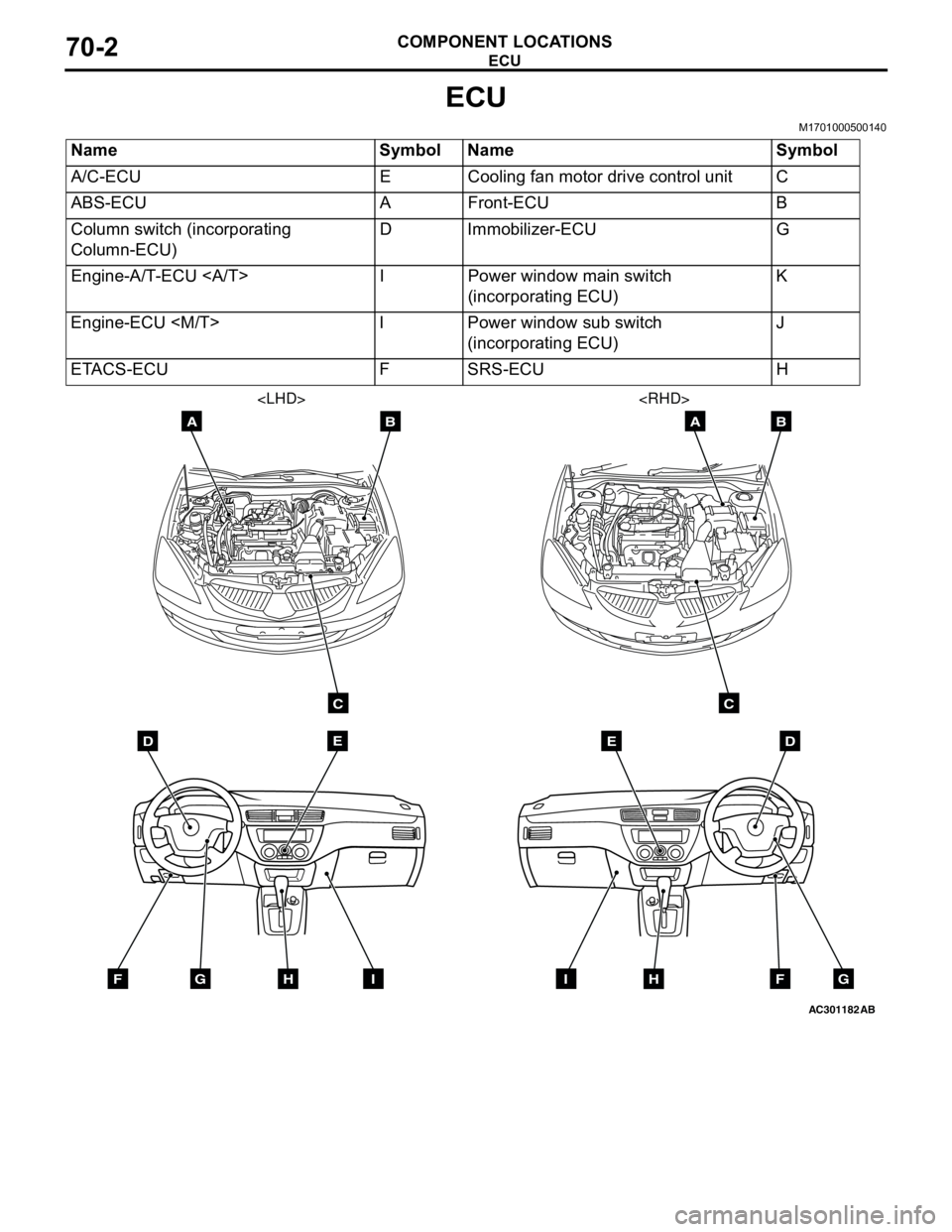
M1701000500140
Name Symbol Name Symbol
A/C-ECU E Cooling fan motor drive control unit C
ABS-ECU A Front-ECU B
Column switch (incorporating
Column-ECU)D Immobilizer-ECU G
Engine-A/T-ECU I Power window main switch
(incorporating ECU)K
Engine-ECU
(incorporating ECU)J
ETACS-ECU F SRS-ECU H
AC301182
DE
AB
C
FGHI
AB
DE
AB
C
FGHI
Page 590 of 788
ECU
COMPONENT LOCATIONS70-4
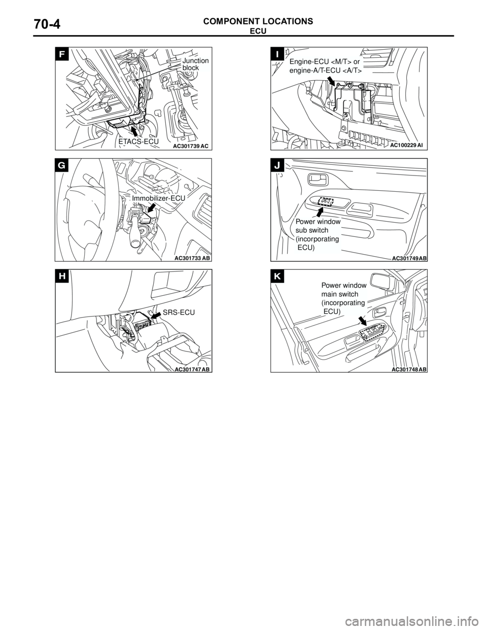
AC301739AC
F
ETACS-ECU
Junction
block
AC301733
AB
Immobilizer-ECU
G
AC301747AB
SRS-ECU
H
AC100229AI
Engine-ECU
engine-A/T-ECU I
AC301749AB
Power window
sub switch
(incorporating
ECU)
J
AC301748AB
Power window
main switch
(incorporating
ECU)
K
Page 591 of 788
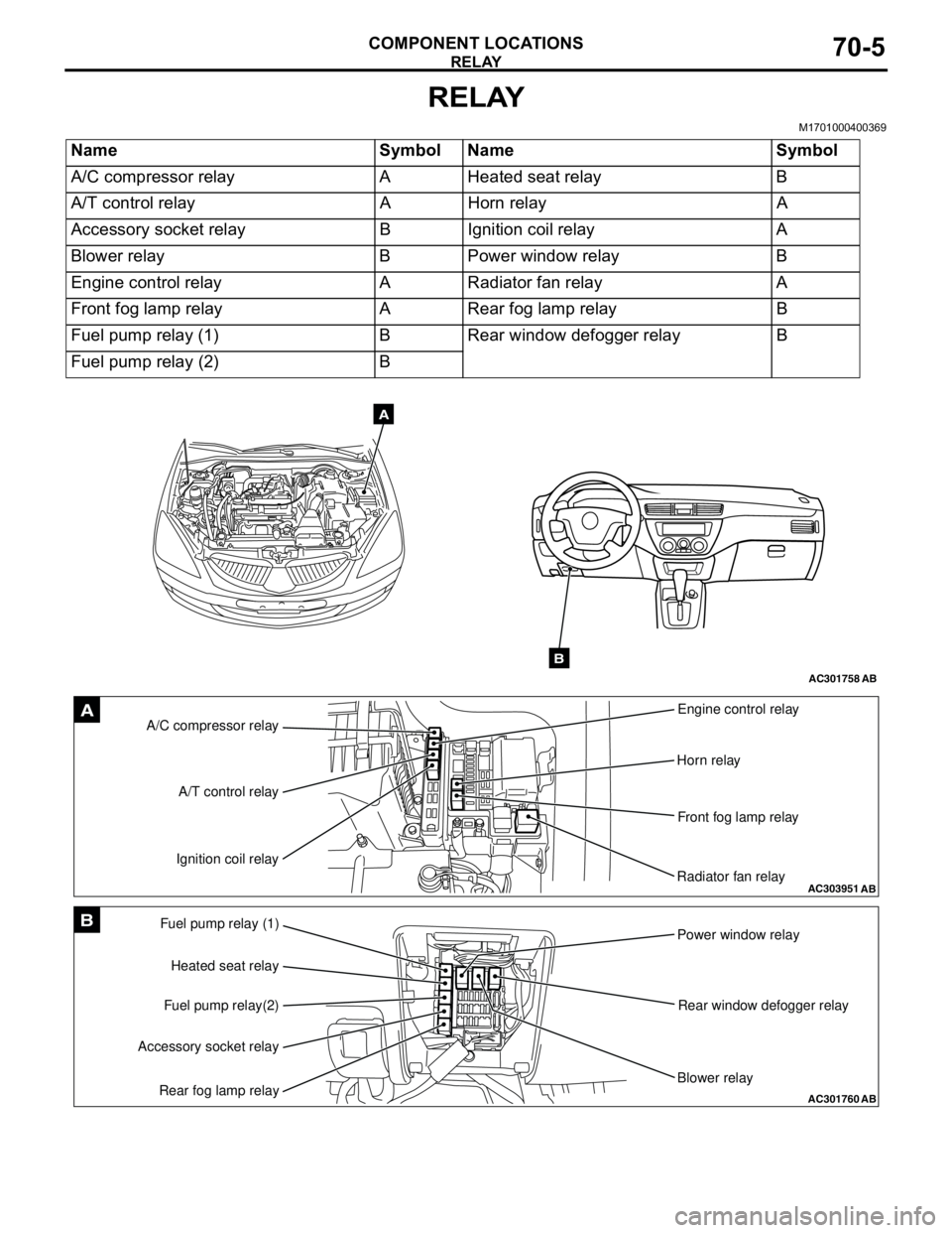
RELAY
COMPONENT LOCATIONS70-5
RELAY
M1701000400369
Name Symbol Name Symbol
A/C compressor relay A Heated seat relay B
A/T control relay A Horn relay A
Accessory socket relay B Ignition coil relay A
Blower relay B Power window relay B
Engine control relay A Radiator fan relay A
Front fog lamp relay A Rear fog lamp relay B
Fuel pump relay (1) B Rear window defogger relay B
Fuel pump relay (2) B
AC301758AB
A
B
AC303951AB
A/C compressor relayEngine control relay
Horn relay
Front fog lamp relay
Radiator fan relay A/T control relay
Ignition coil relayA
AC301760
Fuel pump relay (1)
Power window relay
Rear window defogger relay
Blower relay Heated seat relay
Fuel pump relay(2)
Accessory socket relay
Rear fog lamp relayAB
B
Page 624 of 788
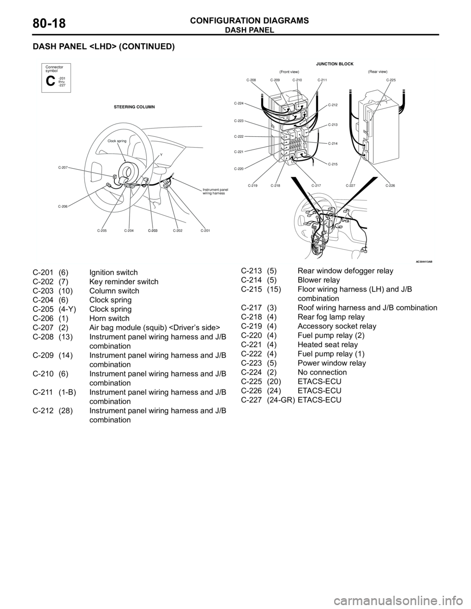
DASH PANEL
CONFIGURATION DIAGRAMS80-18
DASH PANEL
AC304413
Connector
symbol
-201
thru
-227C
STEERING COLUMN
C-207
C-206
C-201 C-202 C-203
C-203 C-204 C-205Instrument panel
wiring harness
Clock spring
Y
AB
(Front view)(Rear view)
C-208 C-209 C-210 C-211
C-212
C-213
C-214
C-215
C-217 C-218 C-219 C-220 C-221 C-222 C-223 C-224C-225
C-226 C-227
JUNCTION BLOCK
C-201 (6) Ignition switch
C-202 (7) Key reminder switch
C-203 (10) Column switch
C-204 (6) Clock spring
C-205 (4-Y) Clock spring
C-206 (1) Horn switch
C-207 (2) Air bag module (squib)
C-208 (13) Instrument panel wiring harness and J/B
combination
C-209 (14) Instrument panel wiring harness and J/B
combination
C-210 (6) Instrument panel wiring harness and J/B
combination
C-211 (1-B) Instrument panel wiring harness and J/B
combination
C-212 (28) Instrument panel wiring harness and J/B
combinationC-213 (5) Rear window defogger relay
C-214 (5) Blower relay
C-215 (15) Floor wiring harness (LH) and J/B
combination
C-217 (3) Roof wiring harness and J/B combination
C-218 (4) Rear fog lamp relay
C-219 (4) Accessory socket relay
C-220 (4) Fuel pump relay (2)
C-221 (4) Heated seat relay
C-222 (4) Fuel pump relay (1)
C-223 (5) Power window relay
C-224 (2) No connection
C-225 (20) ETACS-ECU
C-226 (24) ETACS-ECU
C-227 (24-GR) ETACS-ECU
Page 627 of 788
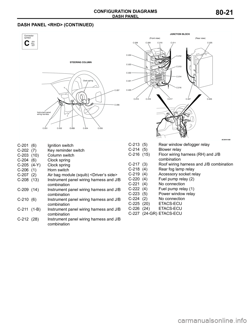
DASH PANEL
CONFIGURATION DIAGRAMS80-21
DASH PANEL
AC304414AB
(Front view)(Rear view)
C-208 C-209 C-210 C-211
C-212
C-213
C-214
C-216
C-217 C-218 C-219 C-220 C-221 C-222 C-223 C-224C-225
C-226 C-227
JUNCTION BLOCKConnector
symbol
-201
thru
-227C
STEERING COLUMN
C-207
C-206
C-205 C-204 C-203
C-203 C-202 C-201 Instrument panel
wiring harness
Clock spring
Y
C-201 (6) Ignition switch
C-202 (7) Key reminder switch
C-203 (10) Column switch
C-204 (6) Clock spring
C-205 (4-Y) Clock spring
C-206 (1) Horn switch
C-207 (2) Air bag module (squib)
C-208 (13) Instrument panel wiring harness and J/B
combination
C-209 (14) Instrument panel wiring harness and J/B
combination
C-210 (6) Instrument panel wiring harness and J/B
combination
C-211 (1-B) Instrument panel wiring harness and J/B
combination
C-212 (28) Instrument panel wiring harness and J/B
combinationC-213 (5) Rear window defogger relay
C-214 (5) Blower relay
C-216 (15) Floor wiring harness (RH) and J/B
combination
C-217 (3) Roof wiring harness and J/B combination
C-218 (4) Rear fog lamp relay
C-219 (4) Accessory socket relay
C-220 (4) Fuel pump relay (2)
C-221 (4) No connection
C-222 (4) Fuel pump relay (1)
C-223 (5) Power window relay
C-224 (2) No connection
C-225 (20) ETACS-ECU
C-226 (24) ETACS-ECU
C-227 (24-GR) ETACS-ECU
Page 632 of 788
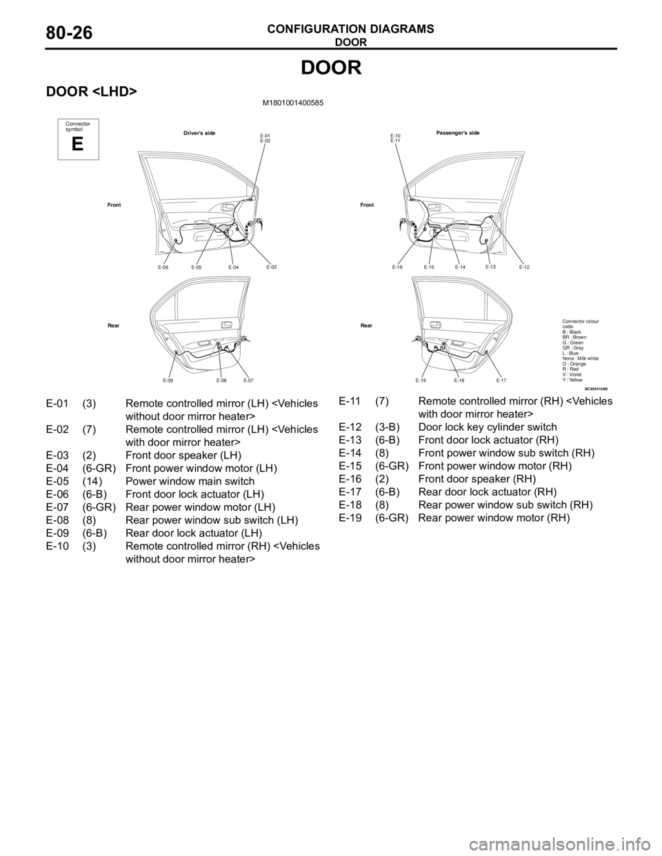
DOOR
CONFIGURATION DIAGRAMS80-26
DOOR
DOOR
AC304415
Connector
symbol
E
Driver's sideE-01
E-02
E-03
E-04
E-05 E-06
E-07
E-08 E-09
Front
RearPassenger's side
E-10
E-11
E-12
E-14
E-15 E-16
E-17
E-18 E-19
Front
Rear
AB
E-13
Connector colour
code
B : Black
BR : Brown
G : Green
GR : Gray
L : Blue
None : Milk white
O : Orange
R : Red
V : Violet
Y : Yellow
E-01 (3) Remote controlled mirror (LH)
E-02 (7) Remote controlled mirror (LH)
E-03 (2) Front door speaker (LH)
E-04 (6-GR) Front power window motor (LH)
E-05 (14) Power window main switch
E-06 (6-B) Front door lock actuator (LH)
E-07 (6-GR) Rear power window motor (LH)
E-08 (8) Rear power window sub switch (LH)
E-09 (6-B) Rear door lock actuator (LH)
E-10 (3) Remote controlled mirror (RH)
E-12 (3-B) Door lock key cylinder switch
E-13 (6-B) Front door lock actuator (RH)
E-14 (8) Front power window sub switch (RH)
E-15 (6-GR) Front power window motor (RH)
E-16 (2) Front door speaker (RH)
E-17 (6-B) Rear door lock actuator (RH)
E-18 (8) Rear power window sub switch (RH)
E-19 (6-GR) Rear power window motor (RH)
Page 633 of 788
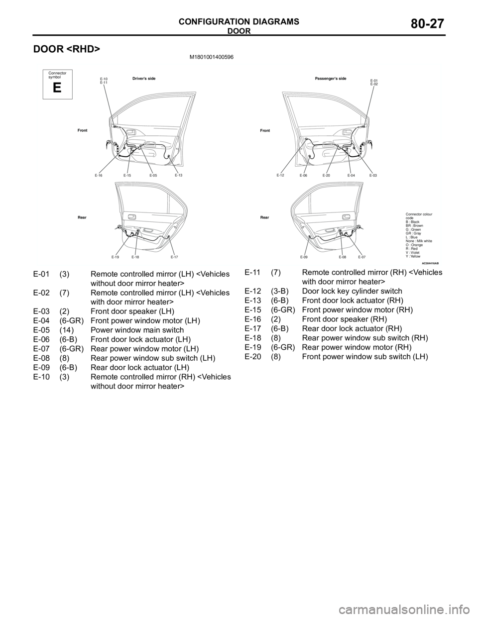
DOOR
CONFIGURATION DIAGRAMS80-27
DOOR
AC304416
Connector
symbol
E
Driver's sideE-10
E-11
E-13
E-05
E-15 E-16
E-17
E-18 E-19
Front
RearPassenger's side
E-01
E-02
E-03
E-04
E-20 E-06
E-07
E-08 E-09
Front
Rear
AB
E-12
Connector colour
code
B : Black
BR : Brown
G : Green
GR : Gray
L : Blue
None : Milk white
O : Orange
R : Red
V : Violet
Y : Yellow
E-01 (3) Remote controlled mirror (LH)
E-02 (7) Remote controlled mirror (LH)
E-03 (2) Front door speaker (LH)
E-04 (6-GR) Front power window motor (LH)
E-05 (14) Power window main switch
E-06 (6-B) Front door lock actuator (LH)
E-07 (6-GR) Rear power window motor (LH)
E-08 (8) Rear power window sub switch (LH)
E-09 (6-B) Rear door lock actuator (LH)
E-10 (3) Remote controlled mirror (RH)
E-12 (3-B) Door lock key cylinder switch
E-13 (6-B) Front door lock actuator (RH)
E-15 (6-GR) Front power window motor (RH)
E-16 (2) Front door speaker (RH)
E-17 (6-B) Rear door lock actuator (RH)
E-18 (8) Rear power window sub switch (RH)
E-19 (6-GR) Rear power window motor (RH)
E-20 (8) Front power window sub switch (LH)
Page 634 of 788
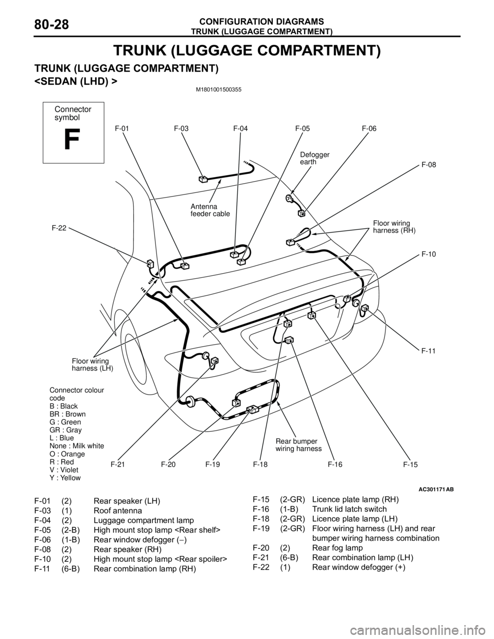
TRUNK (LUGGAGE COMPARTMENT)
CONFIGURATION DIAGRAMS80-28
TRUNK (LUGGAGE COMPARTMENT)
TRUNK (LUGGAGE COMPARTMENT)
M1801001500355
AC301171AB
F-01 F-04 F-05 F-06
F-08
F-10
F-11
F-18
F-16 F-19 Floor wiring
harness (LH) F-22Defogger
earth
Floor wiring
harness (RH)F-03
F-15F-21
Rear bumper
wiring harness
Antenna
feeder cable
Connector colour
code
B : Black
BR : Brown
G : Green
GR : Gray
L : Blue
None : Milk white
O : Orange
R : Red
V : Violet
Y : Yellow
F-20
Connector
symbol
F
F-01 (2) Rear speaker (LH)
F-03 (1) Roof antenna
F-04 (2) Luggage compartment lamp
F-05 (2-B) High mount stop lamp
F-06 (1-B) Rear window defogger (−)
F-08 (2) Rear speaker (RH)
F-10 (2) High mount stop lamp
F-11 (6-B) Rear combination lamp (RH)F-15 (2-GR) Licence plate lamp (RH)
F-16 (1-B) Trunk lid latch switch
F-18 (2-GR) Licence plate lamp (LH)
F-19 (2-GR) Floor wiring harness (LH) and rear
bumper wiring harness combination
F-20 (2) Rear fog lamp
F-21 (6-B) Rear combination lamp (LH)
F-22 (1) Rear window defogger (+)