window MITSUBISHI LANCER 2005 Owner's Manual
[x] Cancel search | Manufacturer: MITSUBISHI, Model Year: 2005, Model line: LANCER, Model: MITSUBISHI LANCER 2005Pages: 788, PDF Size: 45.98 MB
Page 307 of 788
DOOR
BODY42-29
3. If the operation current is outside the standard
value, refer to GROUP 54B, Troubleshooting
P.54B-17, refer to GROUP 54C, Troubleshooting
P.54C-4.
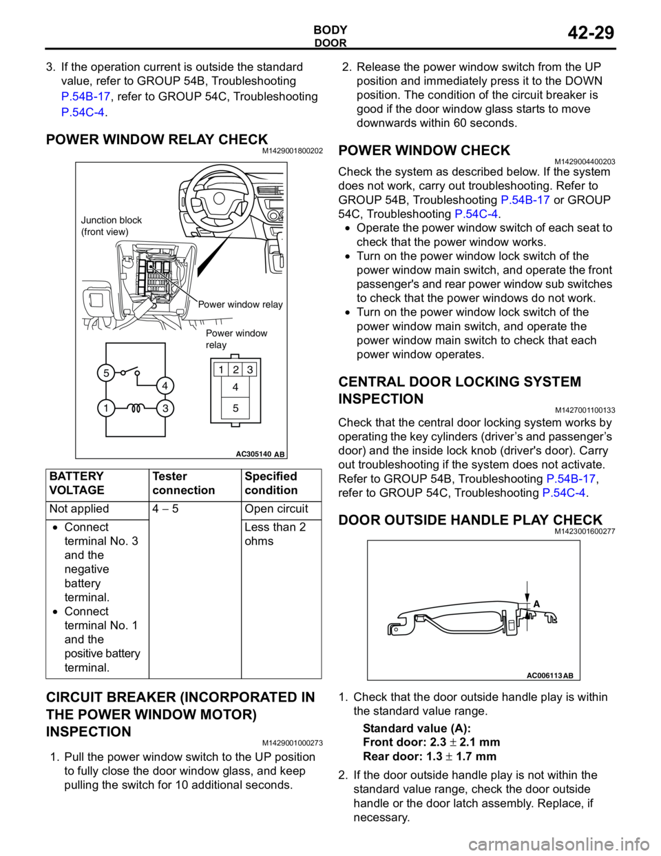
POWER WINDOW RELAY CHECKM1429001800202
CIRCUIT BREAKER (INCORPORATED IN
THE POWER WINDOW MOTOR)
INSPECTION
M1429001000273
1. Pull the power window switch to the UP position
to fully close the door window glass, and keep
pulling the switch for 10 additional seconds.2. Release the power window switch from the UP
position and immediately press it to the DOWN
position. The condition of the circuit breaker is
good if the door window glass starts to move
downwards within 60 seconds.
POWER WINDOW CHECKM1429004400203
Check the system as described below. If the system
does not work, carry out troubleshooting. Refer to
GROUP 54B, Troubleshooting P.54B-17 or GROUP
54C, Troubleshooting P.54C-4.
•Operate the power window switch of each seat to
check that the power window works.
•Turn on the power window lock switch of the
power window main switch, and operate the front
passenger's and rear power window sub switches
to check that the power windows do not work.
•Turn on the power window lock switch of the
power window main switch, and operate the
power window main switch to check that each
power window operates.
CENTRAL DOOR LOCKING SYSTEM
INSPECTION
M1427001100133
Check that the central door locking system works by
operating the key cylinders (driver’s and passenger’s
door) and the inside lock knob (driver's door). Carry
out troubleshooting if the system does not activate.
Refer to GROUP 54B, Troubleshooting P.54B-17,
refer to GROUP 54C, Troubleshooting P.54C-4.
DOOR OUTSIDE HANDLE PLAY CHECKM1423001600277
1. Check that the door outside handle play is within
the standard value range.
Standard value (A):
Front door: 2.3 ± 2.1 mm
Rear door: 1.3 ± 1.7 mm
2. If the door outside handle play is not within the
standard value range, check the door outside
handle or the door latch assembly. Replace, if
necessary. BATTERY
VOLTAGETester
connectionSpecified
condition
Not applied 4 − 5 Open circuit
•Connect
terminal No. 3
and the
negative
battery
terminal.
•Connect
terminal No. 1
and the
positive battery
terminal.Less than 2
ohms
AC305140
123
4
5
1
3 4 5
AB
Junction block
(front view)
Power window relay
Power window
relay
AC006113
AB
A
Page 310 of 788
DOOR
BODY42-32
INSTALLATION SERVICE POINT
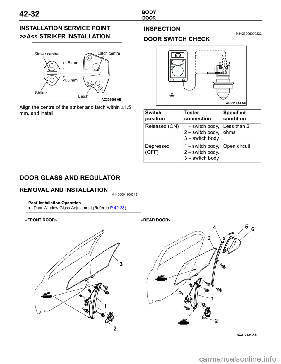
>>A<< STRIKER INSTALLATION
Align the centre of the striker and latch within ±1.5
mm, and install.
INSPECTIONM1423006000322
DOOR SWITCH CHECK
DOOR GLASS AND REGULATOR
REMOVAL AND INSTALLATIONM1429001300315
AC305098AB
Striker centre
StrikerLatch centre
Latch +1.5 mm
-1.5 mm
Switch
positionTester
connectionSpecified
condition
Released (ON) 1 − switch body,
2 − switch body,
3 − switch body Less than 2
ohms
Depressed
(OFF)1 − switch body,
2 − switch body,
3 − switch body Open circuit
AC211414
123
AC
Post-installation Operation
•Door Window Glass Adjustment (Refer to P.42-28).
AC212124AB
1
23
1
2 345
6
Page 311 of 788
DOOR
BODY42-33
AC305108
NOTE
: Clip positions
: Claw positions
View A
B
B
B
B C
CC
CC
CC
C
Section B - B
Door trim
ClipSection C - C
AB
Door trim
Claw
7
7
7 7
A
AC305109
NOTE
: Clip positions
: Claw positions
E
E
E
E F
FF
FF
FF
F
Section E - EView D
Door trim
ClipSection F - F
Door trim
Claw
D
7
7 7
AB
7
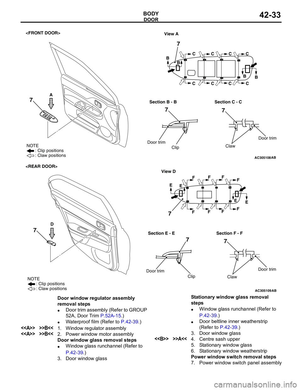
Door window regulator assembly
removal steps
•Door trim assembly (Refer to GROUP
52A, Door Trim P.52A-15.)
•Waterproof film (Refer to P.42-39.)
<> >>B<<1. Window regulator assembly
<> >>B<<2. Power window motor assembly
Door window glass removal steps
•Window glass runchannel (Refer to
P.42-39.)
3. Door window glassStationary window glass removal
steps
•Window glass runchannel (Refer to
P.42-39.)
•Door beltline inner weatherstrip
(Refer to P.42-39.)
3. Door window glass<> >>A<<4. Centre sash upper
5. Stationary window glass
6. Stationary window weatherstrip
Power window switch removal steps
7. Power window switch panel assembly
Page 312 of 788
Page 313 of 788

DOOR
BODY42-35
CAUTION
The anti-trap function does not work until the
power window switch completes learning the
fully closed position (It is because the anti-trap
function is reset).
3. Operate the power window switch and fully close
the door window glass. The power window
activates for 0.7 seconds and stops automatically
when the power window switch is pressed once.
Repeat this operation until the door window glass
fully closes and release the switch once. Then,
hold the power window switch to the fully closed
side again for one second so that the power
window switch completes learning the fully closed
position.
NOTE: If the power window switch is operated to
open the door window glass while the switch is
learning, learning will be cancelled. If this
happens, return to step 2.
How to make the power window switch
learn the fully closed position when the
power window switch is replaced with a
new one
CAUTION
The anti-trap function does not work until the
power window switch completes learning the
fully closed position (It is because the anti-trap
function is reset).
Operate the power window main switch to fully close
the door window glass by one-shot up action so that
the power window switch will complete learning
(Initialisation is not needed).
NOTE: When the power window sub switch of each
seat is replaced, operate the power window main
switch to fully close the applicable power window by
one-shot up action (It is because the power window
sub switch does not have one-shot up/down
function).
Page 315 of 788
DOOR
BODY42-37
INSTALLATION SERVICE POINTS
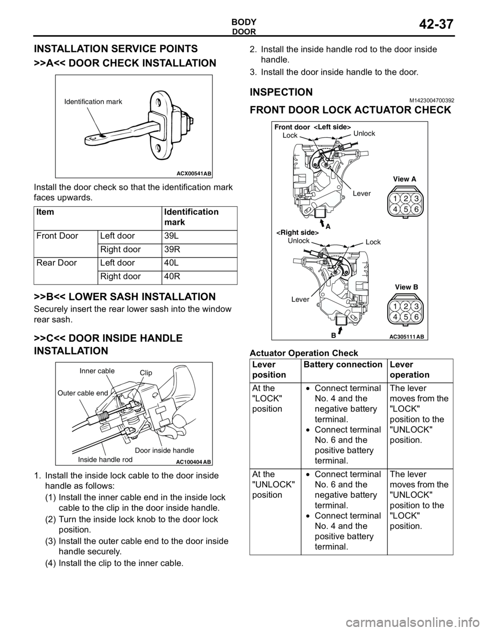
>>A<< DOOR CHECK INSTALLATION
Install the door check so that the identification mark
faces upwards.
>>B<< LOWER SASH INSTALLATION
Securely insert the rear lower sash into the window
rear sash.
>>C<< DOOR INSIDE HANDLE
INSTALLATION
1. Install the inside lock cable to the door inside
handle as follows:
(1) Install the inner cable end in the inside lock
cable to the clip in the door inside handle.
(2) Turn the inside lock knob to the door lock
position.
(3) Install the outer cable end to the door inside
handle securely.
(4) Install the clip to the inner cable.2. Install the inside handle rod to the door inside
handle.
3. Install the door inside handle to the door.
INSPECTIONM1423004700392
FRONT DOOR LOCK ACTUATOR CHECK
Actuator Operation Check Item Identification
mark
Front Door Left door 39L
Right door 39R
Rear Door Left door 40L
Right door 40R
ACX00541
Identification mark
AB
AC100404
AB
Clip Inner cable
Outer cable end
Inside handle rodDoor inside handleLever
positionBattery connection Lever
operation
At the
"LOCK"
position•Connect terminal
No. 4 and the
negative battery
terminal.
•Connect terminal
No. 6 and the
positive battery
terminal.The lever
moves from the
"LOCK"
position to the
"UNLOCK"
position.
At the
"UNLOCK"
position•Connect terminal
No. 6 and the
negative battery
terminal.
•Connect terminal
No. 4 and the
positive battery
terminal.The lever
moves from the
"UNLOCK"
position to the
"LOCK"
position.
42
53
6 1
42
53
6 1
AC305111B
A
AB
LockUnlock
View A
View B Unlock
Lock Front door
Lever
Page 317 of 788
DOOR
BODY42-39
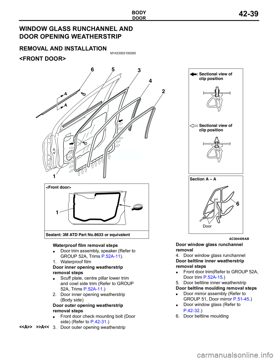
WINDOW GLASS RUNCHANNEL AND
DOOR OPENING WEATHERSTRIP
REMOVAL AND INSTALLATIONM1423003100290
AC304409AB
Section A – A
Sealant: 3M ATD Part No.8633 or equivalentDoor
: Sectional view of
clip position
: Sectional view of
clip position
6 2
1
4
365
A A
1
Waterproof film removal steps
•Door trim assembly, speaker (Refer to
GROUP 52A, Trims P.52A-11).
1. Waterproof film
Door inner opening weatherstrip
removal steps
•Scuff plate, centre pillar lower trim
and cowl side trim (Refer to GROUP
52A, Trims P.52A-11.)
2. Door inner opening weatherstrip
(Body side)
Door outer opening weatherstrip
removal steps
•Front door check mounting bolt (Door
side) (Refer to P.42-31.)
<> >>A<<3. Door outer opening weatherstripDoor window glass runchannel
removal
4. Door window glass runchannel
Door beltline inner weatherstrip
removal steps
•Front door trim(Refer to GROUP 52A,
Door trim P.52A-15.)
5. Door beltline inner weatherstrip
Door beltline moulding removal steps
•Door mirror assembly (Refer to
GROUP 51, Door mirror P.51-45.)
•Door window glass (Refer to
P.42-32.)
6. Door beltline moulding
Page 318 of 788
DOOR
BODY42-40
AC304418AB
Section A – A
Door
: Sectional view of
clip position
: Sectional view of
clip position
6 2 4
5
7
A A
3
Section B – B
Door
6
3
6
BB
Sealant: 3M ATD Part No.8633 or equivalent
1
1
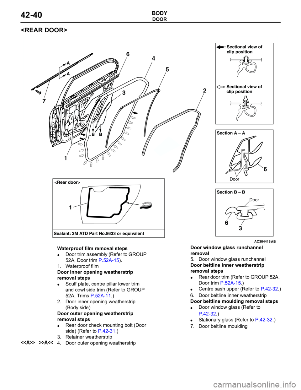
Waterproof film removal steps
•Door trim assembly (Refer to GROUP
52A, Door trim P.52A-15).
1. Waterproof film
Door inner opening weatherstrip
removal steps
•Scuff plate, centre pillar lower trim
and cowl side trim (Refer to GROUP
52A, Trims P.52A-11.)
2. Door inner opening weatherstrip
(Body side)
Door outer opening weatherstrip
removal steps
•Rear door check mounting bolt (Door
side) (Refer to P.42-31.)
3. Retainer weatherstrip
<> >>A<<4. Door outer opening weatherstripDoor window glass runchannel
removal
5. Door window glass runchannel
Door beltline inner weatherstrip
removal steps
•Rear door trim (Refer to GROUP 52A,
Door trim P.52A-15.)
•Centre sash upper (Refer to P.42-32.)
6. Door beltline inner weatherstrip
Door beltline moulding removal steps
•Door window glass (Refer to
P.42-32.)
•Stationary glass (Refer to P.42-32.)
7. Door beltline moulding
Page 347 of 788

MOULDINGS
EXTERIOR51-9
MOULDINGS
SPECIAL TOOLM1511000601136
ADHESIVEM1511000500749
Tool Number Name Application
MB990449 Window moulding remover Removal of drip moulding
MB990449
Application Specified adhesive
Front fender, front and rear door mouldings Double-sided tape [a: 6 mm width 1.2 mm thickness,
b: 20 mm width 1.2 mm thickness ]
Page 349 of 788
MOULDINGS
EXTERIOR51-11
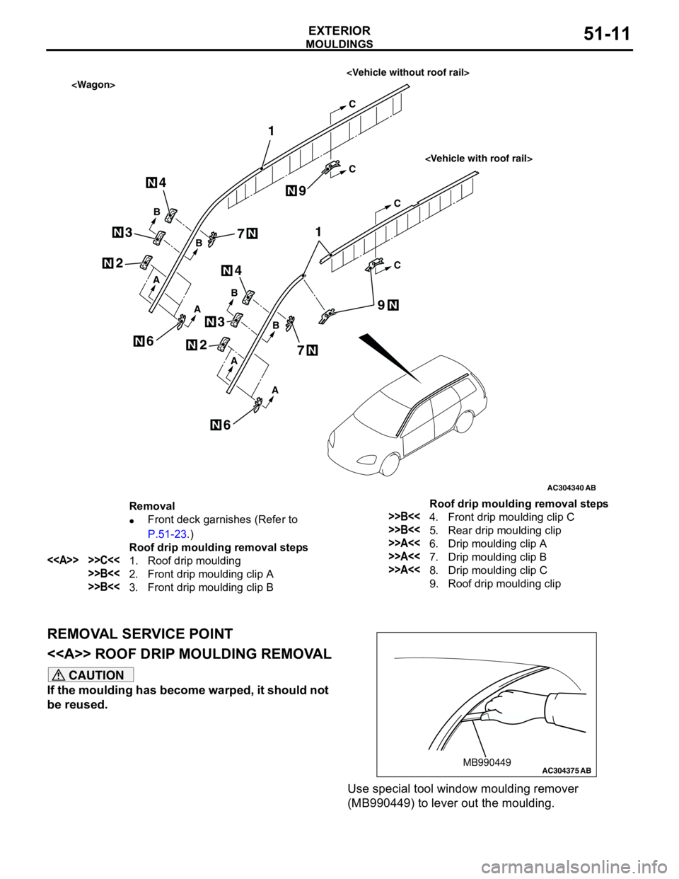
REMOVAL SERVICE POINT
<> ROOF DRIP MOULDING REMOVAL
CAUTION
If the moulding has become warped, it should not
be reused.
Use special tool window moulding remover
(MB990449) to lever out the moulding.
AC304340
1
1
A
A
A
A
AB
B
B
C
C
C
C
B
B
N
N
N
2
N2
4
3
N3
N4
N
6
9
7
N
6N
N
7N
N9
Removal
•Front deck garnishes (Refer to
P.51-23.)
Roof drip moulding removal steps
<> >>C<<1. Roof drip moulding
>>B<<2. Front drip moulding clip A
>>B<<3. Front drip moulding clip B
>>B<<4. Front drip moulding clip C
>>B<<5. Rear drip moulding clip
>>A<<6. Drip moulding clip A
>>A<<7. Drip moulding clip B
>>A<<8. Drip moulding clip C
9. Roof drip moulding clip Roof drip moulding removal steps
AC304375MB990449AB