check engine light MITSUBISHI LANCER 2005 Workshop Manual
[x] Cancel search | Manufacturer: MITSUBISHI, Model Year: 2005, Model line: LANCER, Model: MITSUBISHI LANCER 2005Pages: 788, PDF Size: 45.98 MB
Page 68 of 788

CHARGING SYSTEM
ENGINE ELECTRICAL16-4
2. Turn the ignition switch to the "LOCK" (OFF)
position.
3. Disconnect the negative battery cable.
4. Connect a clamp-type DC test ammeter with a
range of 0 − 120 A to the alternator "B" terminal
output wire.
NOTE: The way of disconnecting the alternator
output wire and of connecting the ammeter is
possibly not found the problem that the output
current is dropping due to the insufficient
connection between terminal "B" and the output
wire.
5. Connect a digital-type voltmeter between the
alternator "B" terminal and the battery (+)
terminal. [Connect the (+) lead of the voltmeter to
the "B" terminal and the connect the (-) lead of the
voltmeter to the battery (+) cable].
6. Reconnect the negative battery cable.
7. Connect a tachometer or the MUT-II/III (Refer to
GROUP 11A − On-vehicle Service − Idle speed
check <4G1> P.11A-11 or GROUP 11C −
On-vehicle Service − Idle speed check <4G6>
P.11C-11).
8. Leave the hood open.
9. Start the engine.
10.With the engine running at 2,500 r/min, turn the
headlamps and other lamps on and off to adjust
the alternator load so that the value displayed on
the ammeter is slightly above 30 A.Adjust the engine speed by gradually decreasing
it until the value displayed on the ammeter is 30
A. Take a reading of the value displayed on the
voltmeter at this time.
Limit: maximum 0.3 V
NOTE: When the alternator output is high and the
value displayed on the ammeter does not
decrease until 30 A, set the value to 40 A. Read
the value displayed on the voltmeter at this time.
When the value range is 40 A, the limit is
maximum 0.4 V.
11.If the value displayed on the voltmeter is above
the limit value, there is probably a malfunction in
the alternator output wire, so check the wiring
between the alternator "B" terminal and the
battery (+) terminal (including fusible link).
If a terminal is not sufficiently tight or if the
harness has become discolored due to
overheating, repair and then test again.
12.After the test, run the engine at idle.
13.Turn off all lamps and the ignition switch.
14.Remove the tachometer or the MUT-II/III.
15.Disconnect the negative battery cable.
16.Disconnect the ammeter and voltmeter.
17.Connect the negative battery cable.
Page 69 of 788
CHARGING SYSTEM
ENGINE ELECTRICAL16-5
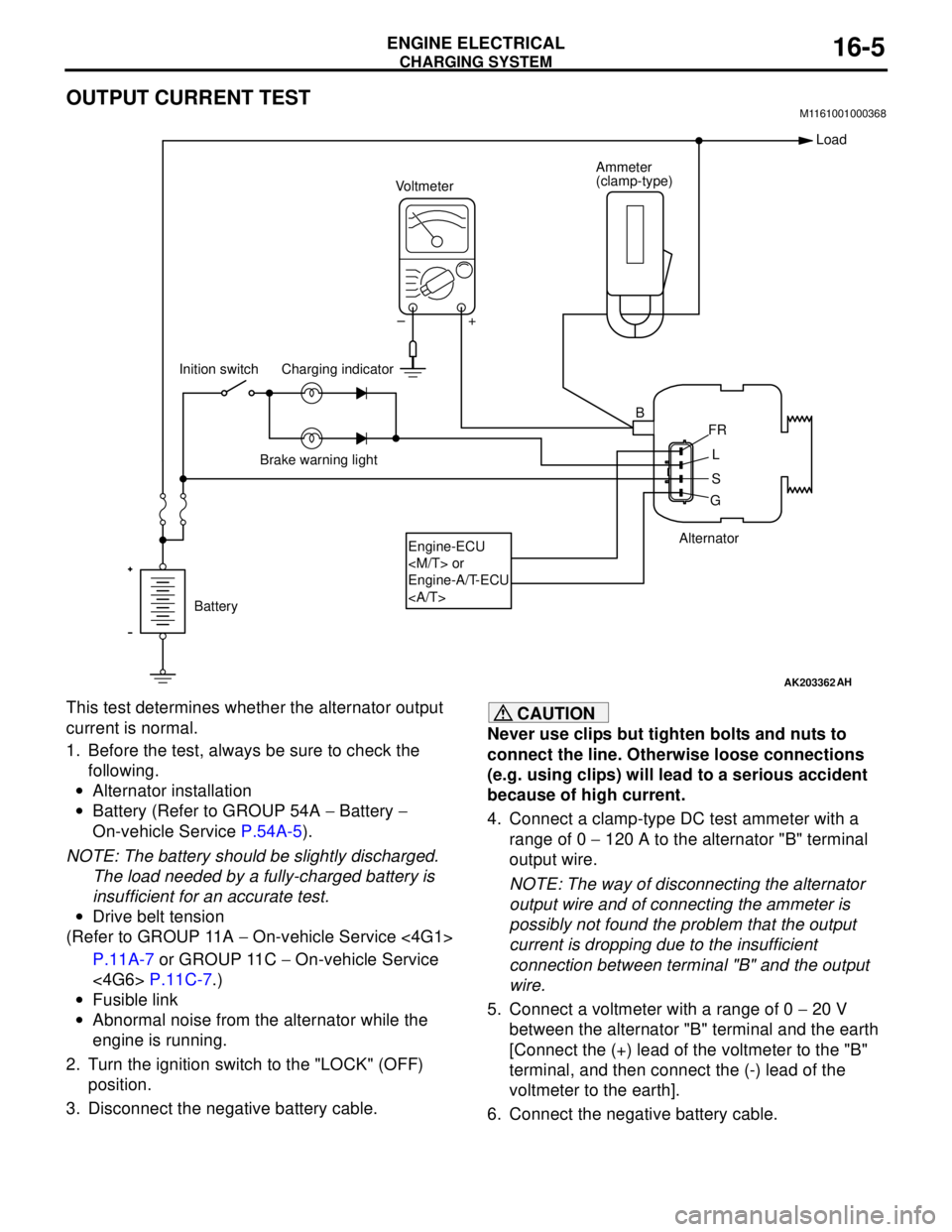
OUTPUT CURRENT TESTM1161001000368
This test determines whether the alternator output
current is normal.
1. Before the test, always be sure to check the
following.
•Alternator installation
•Battery (Refer to GROUP 54A − Battery −
On-vehicle Service P.54A-5).
NOTE: The battery should be slightly discharged.
The load needed by a fully-charged battery is
insufficient for an accurate test.
•Drive belt tension
(Refer to GROUP 11A − On-vehicle Service <4G1>
P.11A-7 or GROUP 11C − On-vehicle Service
<4G6> P.11C-7.)
•Fusible link
•Abnormal noise from the alternator while the
engine is running.
2. Turn the ignition switch to the "LOCK" (OFF)
position.
3. Disconnect the negative battery cable.CAUTION
Never use clips but tighten bolts and nuts to
connect the line. Otherwise loose connections
(e.g. using clips) will lead to a serious accident
because of high current.
4. Connect a clamp-type DC test ammeter with a
range of 0 − 120 A to the alternator "B" terminal
output wire.
NOTE: The way of disconnecting the alternator
output wire and of connecting the ammeter is
possibly not found the problem that the output
current is dropping due to the insufficient
connection between terminal "B" and the output
wire.
5. Connect a voltmeter with a range of 0 − 20 V
between the alternator "B" terminal and the earth
[Connect the (+) lead of the voltmeter to the "B"
terminal, and then connect the (-) lead of the
voltmeter to the earth].
6. Connect the negative battery cable.
AK203362
Alternator Ammeter
(clamp-type)
Voltmeter
Battery Inition switch
Engine-ECU
Engine-A/T-ECU
Load
B
FR
L
S
G +
AH
–
Charging indicator
Brake warning light
Page 70 of 788

CHARGING SYSTEM
ENGINE ELECTRICAL16-6
7. Connect a tachometer or the MUT-II/III (Refer to
GROUP 11A − On-vehicle Service − Idle speed
check <4G1> P.11A-11 or GROUP 11C −
On-vehicle Service − Idle speed check <4G6>
P.11C-11).
8. Leave the hood open.
9. Check that the reading on the voltmeter is equal
to the battery voltage.
NOTE: If the voltage is 0 V, the cause is probably
an open circuit in the wire or fusible link between
the alternator "B" terminal and the battery (+)
terminal.
10.Turn the light switch on to turn on headlamps and
then start the engine.
11.Immediately after setting the headlamps to high
beam and turning the heater blower switch to the
high revolution position, increase the engine
speed to 2,500 r/min and read the maximum
current output value displayed on the ammeter.
Limit: 70 % of normal current outputNOTE: .
•For the nominal current output, refer to the
Alternator Specifications.
•Because the current from the battery will soon
drop after the engine is started, the above step
should be carried out as quickly as possible in
order to obtain the maximum current output
value.
•The current output value will depend on the
electrical load and the temperature of the
alternator body.
•If the electrical load is small while testing, the
specified level of current may not be output
even though the alternator is normal. In such
cases, increase the electrical load by leaving
the headlamps turned on for some time to
discharge the battery or by using the lighting
system in another vehicle, and then test again.
•The specified level of current also may not be
output if the temperature of the alternator body
or the ambient temperature is too high. In such
cases, cool the alternator and then test again.
12.The reading on the ammeter should be above the
limit value. If the reading is below the limit value
and the alternator output wire is normal, remove
the alternator from the engine and check the
alternator.
13.Run the engine at idle after the test.
14.Turn the ignition switch to the "LOCK" (OFF)
position.
15.Remove the tachometer or the MUT-II/III.
16.Disconnect the negative battery cable.
17.Disconnect the ammeter and voltmeter.
18.Connect the negative battery cable.
Page 110 of 788
ENGINE CONTROL
ENGINE AND EMISSION CONTROL17-2
ENGINE CONTROL
GENERAL INFORMATIONM1171000100277
A cable-type accelerator mechanical
suspended-type pedal has been adopted.
SERVICE SPECIFICATIONSM1171000300088
ON-VEHICLE SERVICE
ACCEL CABLE CHECK AND
ADJUSTMENT
M1171000900314
1. Turn A/C and lights OFF. Inspect and adjust at no
load.
2. Warm engine until stabilized at idle.
3. Confirm idle speed is at standard value.
Standard value:
750 ± 50 r/min <4G1>
750 ± 100 r/min <4G6>
4. Stop engine. [ignition switch: LOCK (OFF)
position].
5. Confirm there are no sharp bends in the
accelerator cable.
6. Check the inner cable for correct slack.
Standard value: 1.0 − 2.0 mm
7. If there is too much slack or no slack, adjust play
by the following procedures.
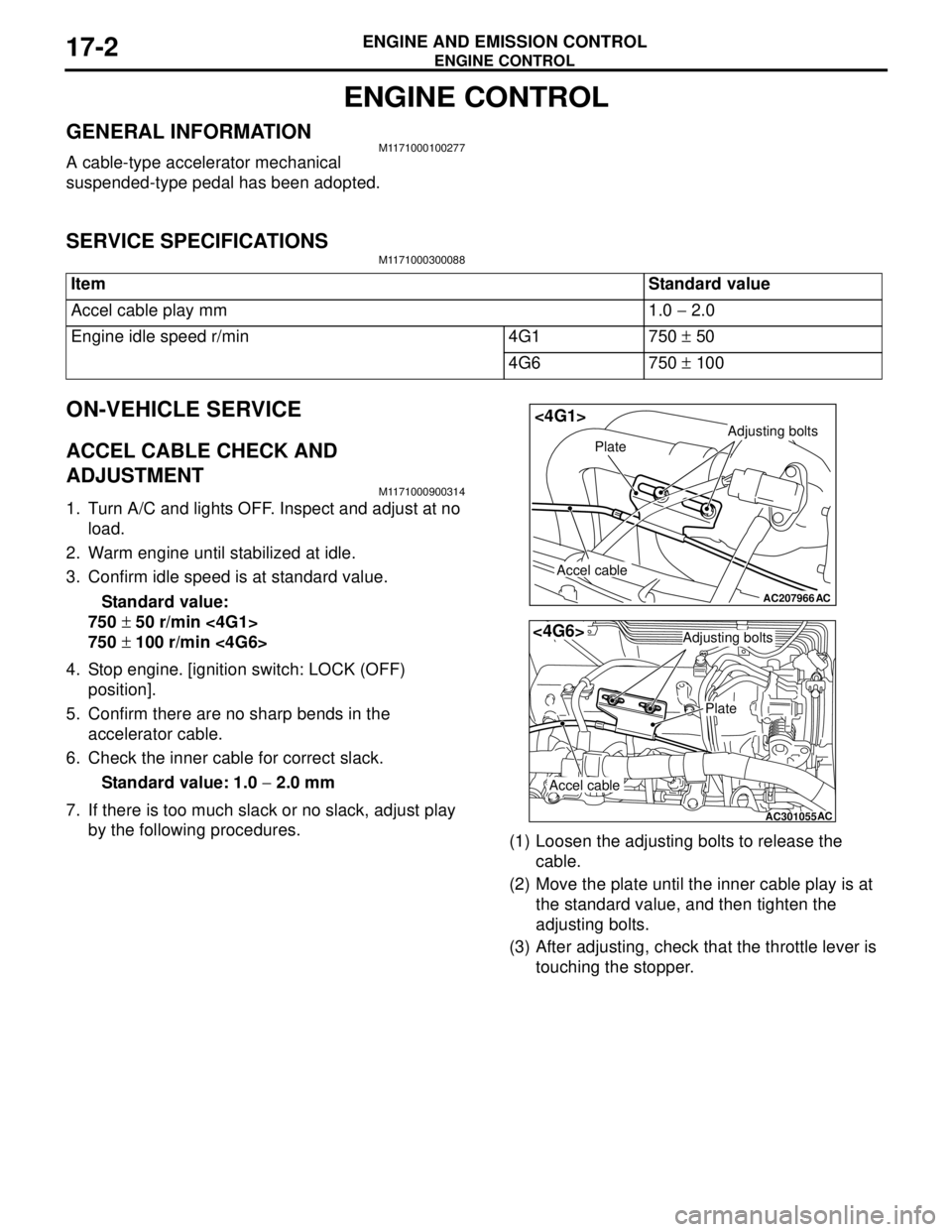
(1) Loosen the adjusting bolts to release the
cable.
(2) Move the plate until the inner cable play is at
the standard value, and then tighten the
adjusting bolts.
(3) After adjusting, check that the throttle lever is
touching the stopper. Item Standard value
Accel cable play mm 1.0 − 2.0
Engine idle speed r/min 4G1 750 ± 50
4G6 750 ± 100
AC207966
Adjusting bolts
Plate
Accel cable
AC
<4G1>
AC301055
Adjusting bolts
Plate
Accel cable
AC
<4G6>
Page 245 of 788
ON-VEHICLE SERVICE
POWER STEERING37-11
ON-VEHICLE SERVICE
STEERING WHEEL FREE PLAY CHECKM1372001000311
1. With the engine running (hydraulic operation), set
the front wheels straight ahead.
2. Measure the play on the steering wheel
circumference before the wheels start to move
when slightly moving the steering wheel in both
directions.
Limit: 30 mm
3. When the play exceeds the limit, check for the
play on the steering shaft and steering linkage
connection. Correct or replace.
4. If the free play still exceeds the limit value, set the
steering wheel straight ahead with the engine
stopped. Load 5 N towards the steering wheel
circumference and check the play.
Standard value (steering wheel play with the
engine stopped): 10 mm or less
5. If the play exceeds the standard value, remove
the steering gear (Refer to P.37-24) and check
the total pinion torque (Refer to P.37-27).
STEERING ANGLE CHECKM1372001100374
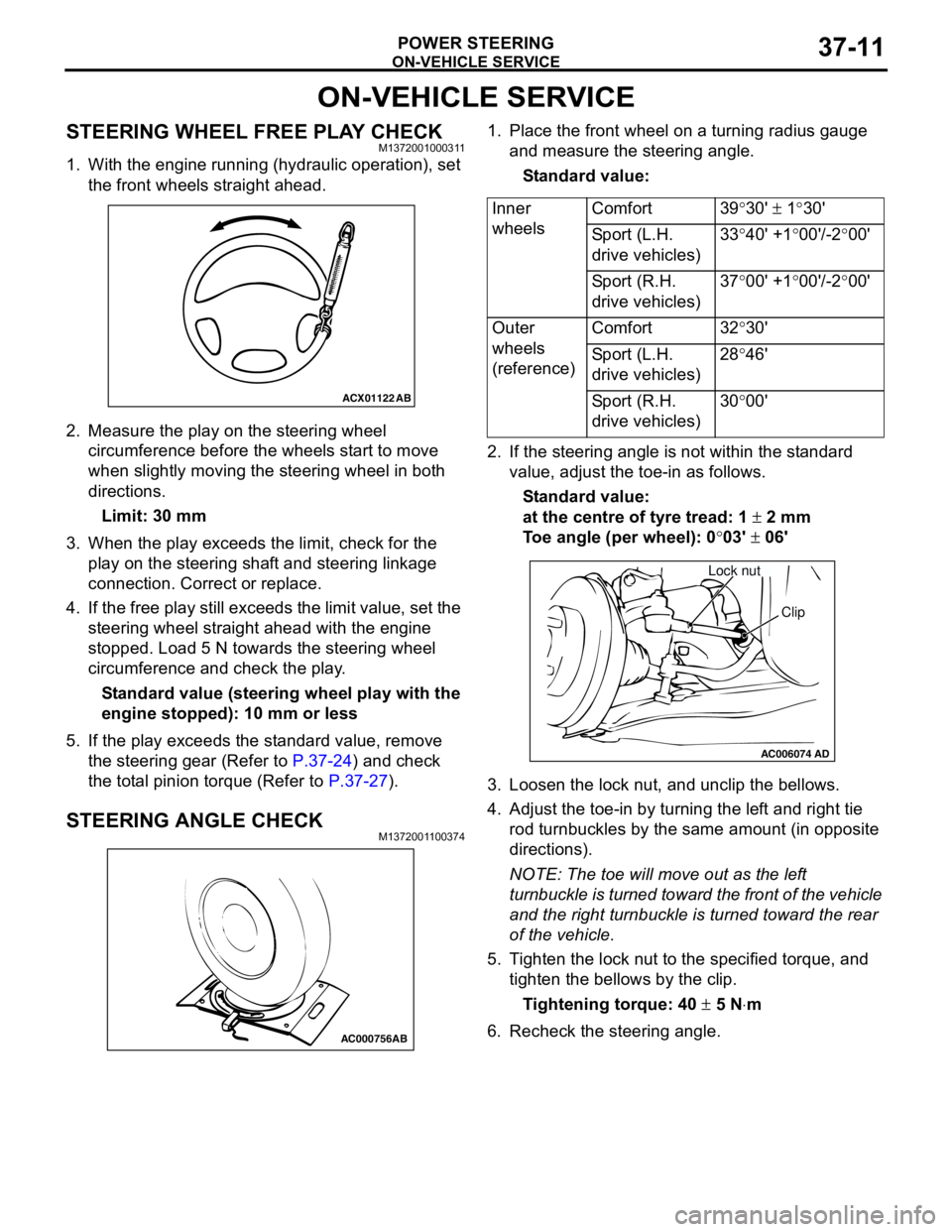
1. Place the front wheel on a turning radius gauge
and measure the steering angle.
Standard value:
2. If the steering angle is not within the standard
value, adjust the toe-in as follows.
Standard value:
at the centre of tyre tread: 1 ± 2 mm
Toe angle (per wheel): 0°03' ± 06'
3. Loosen the lock nut, and unclip the bellows.
4. Adjust the toe-in by turning the left and right tie
rod turnbuckles by the same amount (in opposite
directions).
NOTE: The toe will move out as the left
turnbuckle is turned toward the front of the vehicle
and the right turnbuckle is turned toward the rear
of the vehicle.
5. Tighten the lock nut to the specified torque, and
tighten the bellows by the clip.
Tightening torque: 40 ± 5 N⋅m
6. Recheck the steering angle.
ACX01122
AB
AC000756AB
Inner
wheelsComfort 39°30' ± 1°30'
Sport (L.H.
drive vehicles)33°40' +1°00'/-2°00'
Sport (R.H.
drive vehicles)37°00' +1°00'/-2°00'
Outer
wheels
(reference)Comfort 32°30'
Sport (L.H.
drive vehicles)28°46'
Sport (R.H.
drive vehicles)30°00'
AC006074AD
Lock nut
Clip
Page 439 of 788
COMBINATION METER ASSEMBLY
CHASSIS ELECTRICAL54A-51
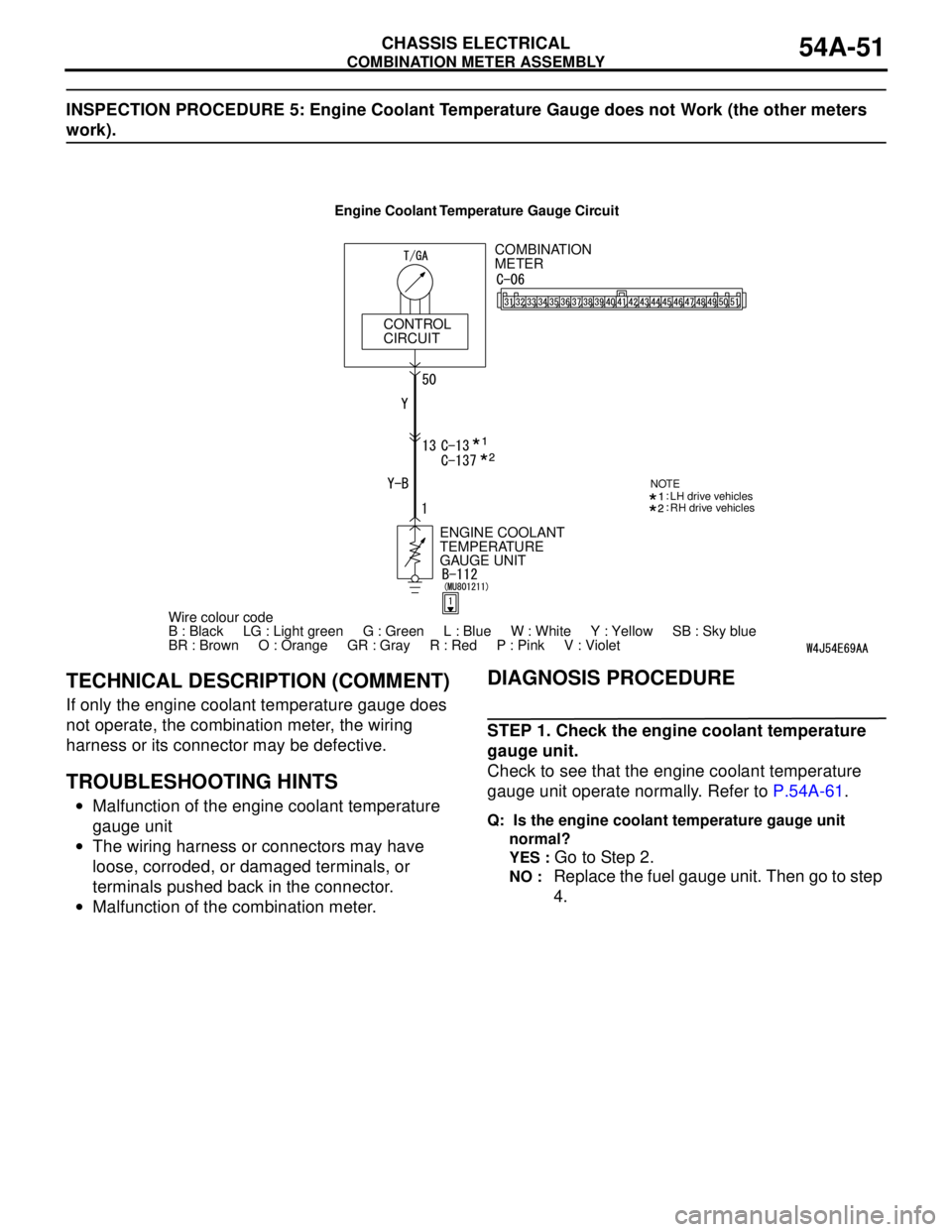
INSPECTION PROCEDURE 5: Engine Coolant Temperature Gauge does not Work (the other meters
work).
TECHNICAL DESCRIPTION (COMMENT)
If only the engine coolant temperature gauge does
not operate, the combination meter, the wiring
harness or its connector may be defective.
TROUBLESHOOTING HINTS
•Malfunction of the engine coolant temperature
gauge unit
•The wiring harness or connectors may have
loose, corroded, or damaged terminals, or
terminals pushed back in the connector.
•Malfunction of the combination meter.
DIAGNOSIS PROCEDURE
STEP 1. Check the engine coolant temperature
gauge unit.
Check to see that the engine coolant temperature
gauge unit operate normally. Refer to P.54A-61.
Q: Is the engine coolant temperature gauge unit
normal?
YES :
Go to Step 2.
NO : Replace the fuel gauge unit. Then go to step
4.
COMBINATION
METER
CONTROL
CIRCUIT
Wire colour code
B : Black LG : Light green G : Green L : Blue W : White Y : Yellow SB : Sky blue
BR : Brown O : Orange GR : Gray R : Red P : Pink V : Violet ENGINE COOLANT
TEMPERATURE
GAUGE UNIT
NOTELH drive vehicles
RH drive vehicles
Engine Coolant Temperature Gauge Circuit
Page 459 of 788
FOG LAMP
CHASSIS ELECTRICAL54A-71
FOG LAMP
SERVICE SPECIFICATIONM1542000300343
SPECIAL TOOLM1542000600894
TROUBLESHOOTINGM1542000701292
When the front fog lamp switch is turned to ON with
the tail lamp or the headlamp on (the tail lamp switch
or the headlamp switch is ON), the fog lamp relay
turns on, and the fog lamps will illuminate.
If the tail lamps or the headlamps are turned off with
the lighting switch OFF while the fog lamps are on,
the front fog lamps turn off at the same time to
prevent unattended operation.
If the tail lamps are turned off by the headlamp
automatic shutdown function, the fog lamps turn off
at the same time. However, if the tail lamps illuminate
again, the fog lamps do not.
The front fog lamps are controlled by the Smart
Wiring System (SWS). For troubleshooting, refer to
respective Groups below.
•Not using SWS monitor: GROUP 54B, SWS
Troubleshooting P.54B-38.
•Using SWS monitor: GROUP 54C, SWS
Troubleshooting P.54C-22.
ON-VEHICLE SERVICE
FRONT FOG LAMP AIMING CHECKM1542001100438
After setting the vehicles to the following condition,
adjust the front fog lamp aiming.
•Check that the tyre inflation pressure is at the
value indicated on the tyre pressure labels.
•Set the vehicle to the unladen condition and park
it on a level surface.
•Have a single person (approximately 75 kg) sit in
the driver’s seat.•Run the engine at a speed of 2000 r/min to fully
charge the battery.
Turn on the front fog lamps and check that the
illumination is within the standard value range.
Standard value: Illuminates to within 40
metres
CAUTION
For the fog lamp which is not being measured,
disconnect that fog lamp’s connector if possible
so that it does not illuminate while carrying out
the adjustment. Furthermore, make sure that the
light axis does not get shifted when
re-connecting the connector.
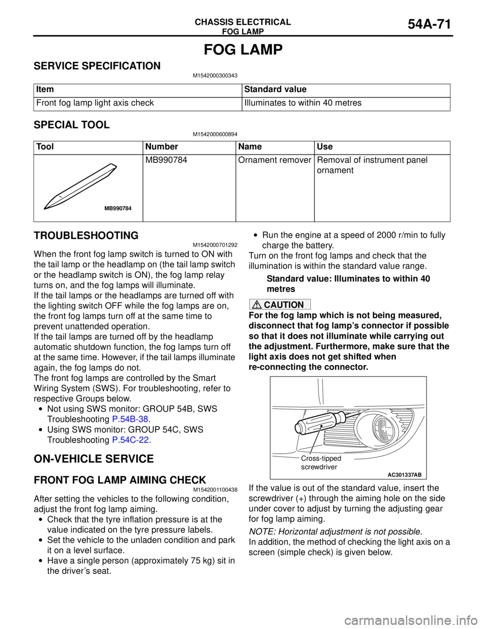
If the value is out of the standard value, insert the
screwdriver (+) through the aiming hole on the side
under cover to adjust by turning the adjusting gear
for fog lamp aiming.
NOTE: Horizontal adjustment is not possible.
In addition, the method of checking the light axis on a
screen (simple check) is given below. Item Standard value
Front fog lamp light axis check Illuminates to within 40 metres
Tool Number Name Use
MB990784 Ornament remover Removal of instrument panel
ornament
MB990784
AC301337
Cross-tipped
screwdriver
AB
Page 551 of 788

TROUBLESHOOTING
HEATER, AIR CONDITIONER AND VENTILATION55-67
CHECK AT ECU TERMINAL
12
345
678
9 10111213141516
AC300861AC
Terminal No. Check item Checking requirement Normal condition
1 Rear defogger switch Defogger switch: ON 0 V
Defogger switch: OFF System voltage
2 Inside/outside air selection
damper motor (outside air)When the damper is moved to
the inside air recirculation
position0 V
When the damper is moved to
the outside air inside air intake
positionSystem voltage
3 Inside/outside air selection
damper motor (inside air)When the damper is moved to
the inside air recirculation
positionSystem voltage
When the damper is moved to
the outside air inside air intake
position0 V
4 Output to the engine-A/T-ECU
(A/C1)A/C stopped 0 V
•A/C switch: ON
•Blower switch: ONSystem voltage
5 Output to the engine-A/T-ECU
(A/C2)When the A/C is under low load System voltage
When the A/C is under high
load0 V
6 Power supply to the A/C
illuminationLighting switch: ON System voltage
7---
8 Blower switch (lo) blower switch: lo System voltage
9---
10 Power supply to the ignition
switch (IG2)Ignition switch: ON System voltage
11 Earth to the A/C illumination Always 0 V
12 Earth Always 0 V
13 Air thermo sensor (outlet side) Sensor probe temperature 25°C
(1.5k ohm)2.2 V
14, 15 - - -
16 Earth to the air thermo sensor Always 0 V
Page 552 of 788

TROUBLESHOOTING
HEATER, AIR CONDITIONER AND VENTILATION55-68
CHECK AT ECU TERMINAL
21
78
6 534
11
10912
AC304990
AB
Terminal No. Check item Checking requirement Normal condition
1 Output to the engine-A/T-ECU
(A/C1)A/C stopped 0 V
•A/C switch: ON
•Blower switch: ONSystem voltage
2 Output to the engine-A/T-ECU
(A/C2)When the A/C is under low load System voltage
When the A/C is under high
load0 V
3 Earth Always 0 V
4 Earth to the air thermo sensor Always 0 V
5 Power supply to the A/C
illuminationLighting switch: ON System voltage
6 Air thermo sensor (outlet side) Sensor probe temperature 25°C
(1.5k ohm)2.2 V
7 Power supply to the ignition
switch (IG2)Ignition switch: ON System voltage
8 Blower switch (lo) blower switch: lo System voltage
9 Rear defogger switch Defogger switch: ON 0 V
Defogger switch: OFF System voltage
10 Inside/outside air selection
damper motor (outside air)When the damper is moved to
the inside air recirculation
position0 V
When the damper is moved to
the outside air inside air intake
positionSystem voltage
11 Inside/outside air selection
damper motor (inside air)When the damper is moved to
the inside air recirculation
positionSystem voltage
When the damper is moved to
the outside air inside air intake
position0 V
12 Earth to the A/C illumination Always 0 V
Page 579 of 788
COMPRESSOR ASSEMBLY AND TENSION PULLEY
HEATER, AIR CONDITIONER AND VENTILATION55-95
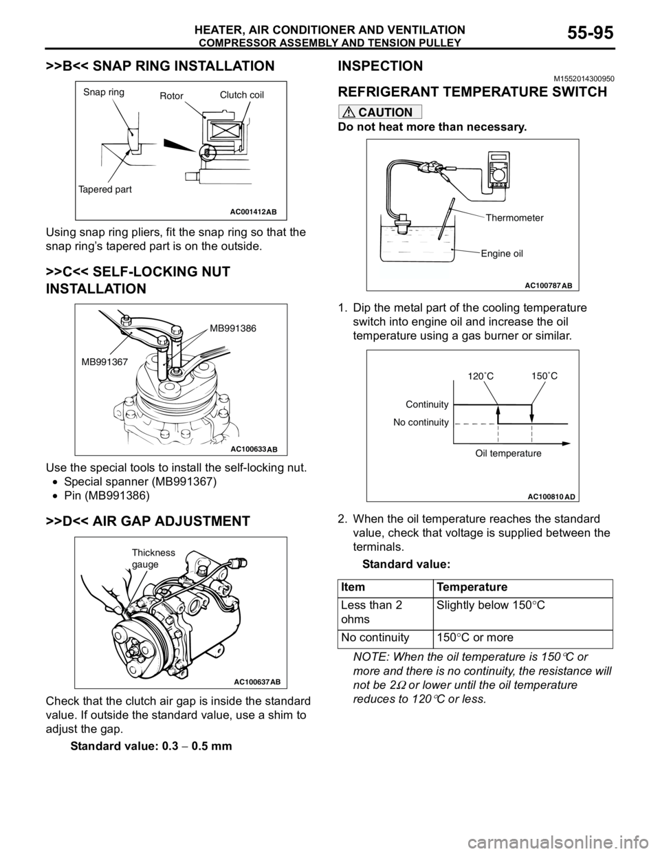
>>B<< SNAP RING INSTALLATION
Using snap ring pliers, fit the snap ring so that the
snap ring’s tapered part is on the outside.
>>C<< SELF-LOCKING NUT
INSTALLATION
Use the special tools to install the self-locking nut.
•Special spanner (MB991367)
•Pin (MB991386)
>>D<< AIR GAP ADJUSTMENT
Check that the clutch air gap is inside the standard
value. If outside the standard value, use a shim to
adjust the gap.
Standard value: 0.3 − 0.5 mm
INSPECTIONM1552014300950
REFRIGERANT TEMPERATURE SWITCH
CAUTION
Do not heat more than necessary.
1. Dip the metal part of the cooling temperature
switch into engine oil and increase the oil
temperature using a gas burner or similar.
2. When the oil temperature reaches the standard
value, check that voltage is supplied between the
terminals.
Standard value:
NOTE: When the oil temperature is 150
°C or
more and there is no continuity, the resistance will
not be 2
Ω or lower until the oil temperature
reduces to 120
°C or less.
AC001412
Snap ring
RotorClutch coil
Tapered part
AB
AC100633AB
MB991386
MB991367
AC100637AB
Thickness
gauge
Item Temperature
Less than 2
ohmsSlightly below 150°C
No continuity 150°C or more
AC100787
Thermometer
Engine oil
AB
AC100810
Continuity
No continuity
Oil temperature
AD
120ËšC150ËšC