CENTRALIZED JUNCTION
CIRCUIT DIAGRAMS90-12
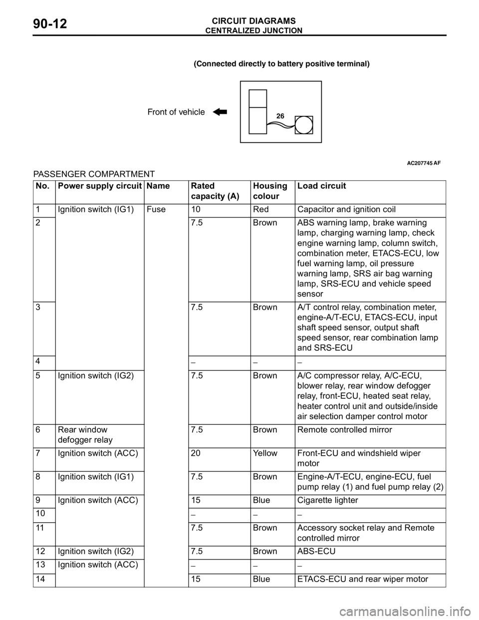
PASSENGER COMPARTMENT
AC207745
(Connected directly to battery positive terminal)
Front of vehicle26
AF
No. Power supply circuit Name Rated
capacity (A)Housing
colourLoad circuit
1 Ignition switch (IG1) Fuse 10 Red Capacitor and ignition coil
2 7.5 Brown ABS warning lamp, brake warning
lamp, charging warning lamp, check
engine warning lamp, column switch,
combination meter, ETACS-ECU, low
fuel warning lamp, oil pressure
warning lamp, SRS air bag warning
lamp, SRS-ECU and vehicle speed
sensor
3 7.5 Brown A/T control relay, combination meter,
engine-A/T-ECU, ETACS-ECU, input
shaft speed sensor, output shaft
speed sensor, rear combination lamp
and SRS-ECU
4
−−−
5 Ignition switch (IG2) 7.5 Brown A/C compressor relay, A/C-ECU,
blower relay, rear window defogger
relay, front-ECU, heated seat relay,
heater control unit and outside/inside
air selection damper control motor
6 Rear window
defogger relay7.5 Brown Remote controlled mirror
7 Ignition switch (ACC) 20 Yellow Front-ECU and windshield wiper
motor
8 Ignition switch (IG1) 7.5 Brown Engine-A/T-ECU, engine-ECU, fuel
pump relay (1) and fuel pump relay (2)
9 Ignition switch (ACC) 15 Blue Cigarette lighter
10
−−−
11 7.5 Brown Accessory socket relay and Remote
controlled mirror
12 Ignition switch (IG2) 7.5 Brown ABS-ECU
13 Ignition switch (ACC)
−−−
14 15 Blue ETACS-ECU and rear wiper motor
