check oil MITSUBISHI LANCER 2005 Workshop Manual
[x] Cancel search | Manufacturer: MITSUBISHI, Model Year: 2005, Model line: LANCER, Model: MITSUBISHI LANCER 2005Pages: 788, PDF Size: 45.98 MB
Page 7 of 788
12-1
GROUP 12
ENGINE
LUBRICATION
CONTENTS
GENERAL INFORMATION . . . . . . . .12-2
SERVICE SPECIFICATION . . . . . . . .12-2
LUBRICANT . . . . . . . . . . . . . . . . . . . .12-2
SEALANT . . . . . . . . . . . . . . . . . . . . . .12-3SPECIAL TOOLS . . . . . . . . . . . . . . . .12-3
ON-VEHICLE SERVICE . . . . . . . . . . .12-4
ENGINE OIL CHECK . . . . . . . . . . . . . . . . . 12-4
ENGINE OIL REPLACEMENT . . . . . . . . . . 12-4
ENGINE OIL FILTER REPLACEMENT . . . . 12-4
OIL PRESSURE CHECK . . . . . . . . . . . . . . 12-5
Page 10 of 788
ON-VEHICLE SERVICE
ENGINE LUBRICATION12-4
ON-VEHICLE SERVICE
ENGINE OIL CHECKM1121000900342
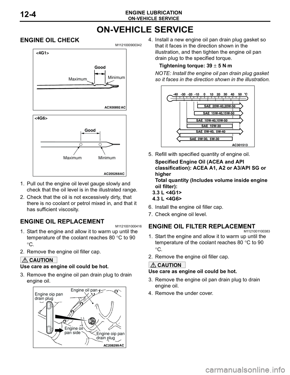
1. Pull out the engine oil level gauge slowly and
check that the oil level is in the illustrated range.
2. Check that the oil is not excessively dirty, that
there is no coolant or petrol mixed in, and that it
has sufficient viscosity.
ENGINE OIL REPLACEMENTM1121001000416
1. Start the engine and allow it to warm up until the
temperature of the coolant reaches 80 °C to 90
°C.
2. Remove the engine oil filler cap.
CAUTION
Use care as engine oil could be hot.
3. Remove the engine oil pan drain plug to drain
engine oil.4. Install a new engine oil pan drain plug gasket so
that it faces in the direction shown in the
illustration, and then tighten the engine oil pan
drain plug to the specified torque.
Tightening torque: 39 ± 5 N⋅m
NOTE: Install the engine oil pan drain plug gasket
so it faces in the direction shown in the illustration.
5. Refill with specified quantity of engine oil.
Specified Engine Oil (ACEA and API
classification): ACEA A1, A2 or A3/API SG or
higher
Total quantity (Includes volume inside engine
oil filter):
3.3 L <4G1>
4.3 L <4G6>
6. Install the engine oil filler cap.
7. Check engine oil level.
ENGINE OIL FILTER REPLACEMENTM1121001100383
1. Start the engine and allow it to warm up until the
temperature of the coolant reaches 80 °C to 90
°C.
2. Remove the engine oil filler cap.
CAUTION
Use care as engine oil could be hot.
3. Remove the engine oil pan drain plug to drain
engine oil.
4. Remove the under cover.
ACX00892 AC
Good
MaximumMinimum
<4G1>
AC205268
Maximum MinimumGood
AC
<4G6>
AC208299
Engine oil pan
AC
Engine oip pan
drain plug
Engine oip pan
drain plug
Engine oil
pan side
AC301513
Page 11 of 788
ON-VEHICLE SERVICE
ENGINE LUBRICATION12-5
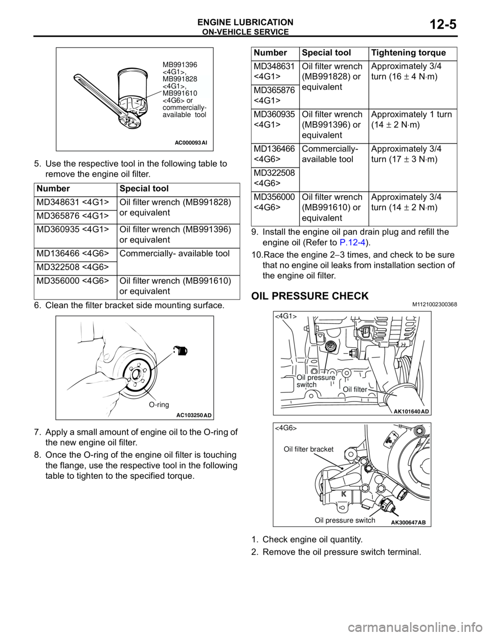
5. Use the respective tool in the following table to
remove the engine oil filter.
6. Clean the filter bracket side mounting surface.
7. Apply a small amount of engine oil to the O-ring of
the new engine oil filter.
8. Once the O-ring of the engine oil filter is touching
the flange, use the respective tool in the following
table to tighten to the specified torque.9. Install the engine oil pan drain plug and refill the
engine oil (Refer to P.12-4).
10.Race the engine 2−3 times, and check to be sure
that no engine oil leaks from installation section of
the engine oil filter.
OIL PRESSURE CHECKM1121002300368
1. Check engine oil quantity.
2. Remove the oil pressure switch terminal. Number Special tool
MD348631 <4G1> Oil filter wrench (MB991828)
or equivalent
MD365876 <4G1>
MD360935 <4G1> Oil filter wrench (MB991396)
or equivalent
MD136466 <4G6> Commercially- available tool
MD322508 <4G6>
MD356000 <4G6> Oil filter wrench (MB991610)
or equivalent
AC000093
MB991396
<4G1>,
MB991828
<4G1>,
MB991610
<4G6> or
commercially-
available tool
AI
AC103250AD
O-ring
Number Special tool Tightening torque
MD348631
<4G1>Oil filter wrench
(MB991828) or
equivalentApproximately 3/4
turn (16 ± 4 N⋅m)
MD365876
<4G1>
MD360935
<4G1>Oil filter wrench
(MB991396) or
equivalentApproximately 1 turn
(14 ± 2 N⋅m)
MD136466
<4G6>Commercially-
available toolApproximately 3/4
turn (17 ± 3 N⋅m)
MD322508
<4G6>
MD356000
<4G6>Oil filter wrench
(MB991610) or
equivalentApproximately 3/4
turn (14 ± 2 N⋅m)
AK101640
<4G1>
Oil pressure
switch
Oil filter
AD
AK300647
AB
<4G6>
Oil filter bracket
Oil pressure switch
Page 12 of 788
ON-VEHICLE SERVICE
ENGINE LUBRICATION12-6
CAUTION
Since sealant is applied to the thread of oil
pressure switch, take care not to damage the oil
pressure switch when removing it.
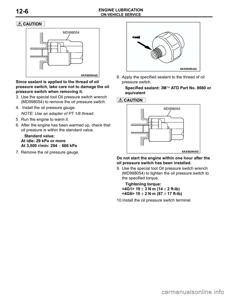
3. Use the special tool Oil pressure switch wrench
(MD998054) to remove the oil pressure switch.
4. Install the oil pressure gauge.
NOTE: Use an adapter of PT 1/8 thread.
5. Run the engine to warm it.
6. After the engine has been warmed up, check that
oil pressure is within the standard value.
Standard value:
At idle: 29 kPa or more
At 3,500 r/min: 294 − 686 kPa
7. Remove the oil pressure gauge.8. Apply the specified sealant to the thread of oil
pressure switch.
Specified sealant: 3M ATD Part No. 8660 or
equivalent
CAUTION
Do not start the engine within one hour after the
oil pressure switch has been installed.
9. Use the special tool Oil pressure switch wrench
(MD998054) to tighten the oil pressure switch to
the specified torque.
Tightening torque:
<4G1> 19 ± 3 N⋅m (14 ± 2 ft-lb)
<4G6> 10 ± 2 N⋅m (87 ± 17 ft-lb)
10.Install the oil pressure switch terminal.
AKX00294
MD998054
AD
AKX00295AD
AKX00294
MD998054
AD
Page 41 of 788
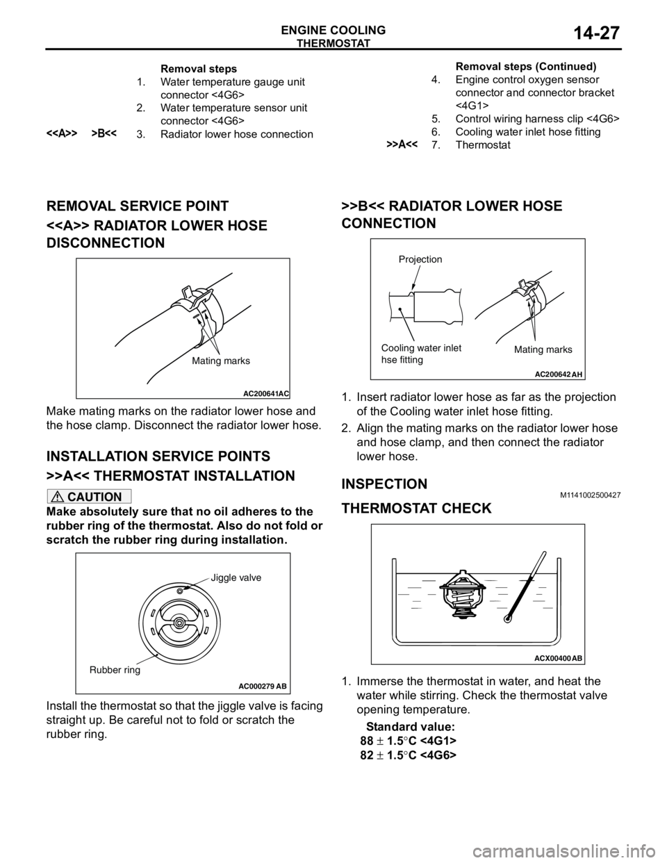
THERMOSTAT
ENGINE COOLING14-27
REMOVAL SERVICE POINT
<> RADIATOR LOWER HOSE
DISCONNECTION
Make mating marks on the radiator lower hose and
the hose clamp. Disconnect the radiator lower hose.
INSTALLATION SERVICE POINTS
>>A<< THERMOSTAT INSTALLATION
CAUTION
Make absolutely sure that no oil adheres to the
rubber ring of the thermostat. Also do not fold or
scratch the rubber ring during installation.
Install the thermostat so that the jiggle valve is facing
straight up. Be careful not to fold or scratch the
rubber ring.
>>B<< RADIATOR LOWER HOSE
CONNECTION
1. Insert radiator lower hose as far as the projection
of the Cooling water inlet hose fitting.
2. Align the mating marks on the radiator lower hose
and hose clamp, and then connect the radiator
lower hose.
INSPECTIONM1141002500427
THERMOSTAT CHECK
1. Immerse the thermostat in water, and heat the
water while stirring. Check the thermostat valve
opening temperature.
Standard value:
88 ± 1.5°C <4G1>
82 ± 1.5°C <4G6>
Removal steps
1. Water temperature gauge unit
connector <4G6>
2. Water temperature sensor unit
connector <4G6>
<> >B<<3. Radiator lower hose connection4. Engine control oxygen sensor
connector and connector bracket
<4G1>
5. Control wiring harness clip <4G6>
6. Cooling water inlet hose fitting>>A<<7. ThermostatRemoval steps (Continued)
AC200641AC
Mating marks
AC000279
Jiggle valve
Rubber ring
AB
AC200642
Mating marks
Projection
Cooling water inlet
hse fitting
AH
ACX00400
AB
Page 48 of 788
Page 58 of 788
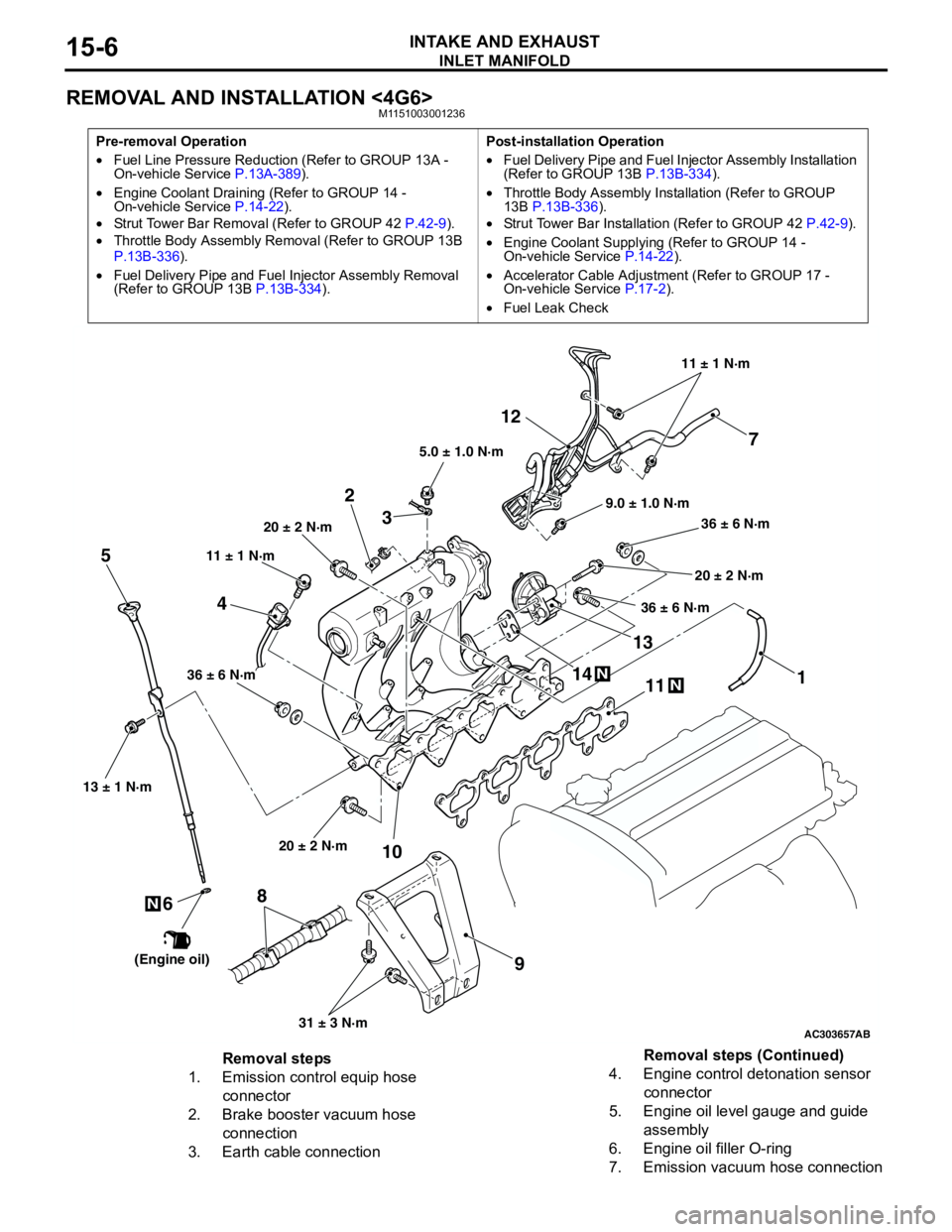
INLET MANIFOLD
INTAKE AND EXHAUST15-6
REMOVAL AND INSTALLATION <4G6>M1151003001236
Pre-removal Operation
•Fuel Line Pressure Reduction (Refer to GROUP 13A -
On-vehicle Service P.13A-389).
•Engine Coolant Draining (Refer to GROUP 14 -
On-vehicle Service P.14-22).
•Strut Tower Bar Removal (Refer to GROUP 42 P.42-9).
•Throttle Body Assembly Removal (Refer to GROUP 13B
P.13B-336).
•Fuel Delivery Pipe and Fuel Injector Assembly Removal
(Refer to GROUP 13B P.13B-334).Post-installation Operation
•Fuel Delivery Pipe and Fuel Injector Assembly Installation
(Refer to GROUP 13B P.13B-334).
•Throttle Body Assembly Installation (Refer to GROUP
13B P.13B-336).
•Strut Tower Bar Installation (Refer to GROUP 42 P.42-9).
•Engine Coolant Supplying (Refer to GROUP 14 -
On-vehicle Service P.14-22).
•Accelerator Cable Adjustment (Refer to GROUP 17 -
On-vehicle Service P.17-2).
•Fuel Leak Check
AC303657
9.0 ± 1.0 N·m11 ± 1 N·m
20 ± 2 N·m
31 ± 3 N·m 36 ± 6 N·m
20 ± 2 N·m
20 ± 2 N·m
36 ± 6 N·m
36 ± 6 N·m
11
9 10 212
N1413N
AB
5.0 ± 1.0 N·m
3
1
11 ± 1 N·m
4
N
13 ± 1 N·m
5
6
(Engine oil)
7
8
Removal steps
1. Emission control equip hose
connector
2. Brake booster vacuum hose
connection
3. Earth cable connection4. Engine control detonation sensor
connector
5. Engine oil level gauge and guide
assembly
6. Engine oil filler O-ring
7. Emission vacuum hose connectionRemoval steps (Continued)
Page 59 of 788
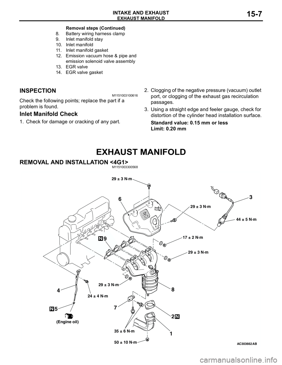
EXHAUST MANIFOLD
INTAKE AND EXHAUST15-7
INSPECTIONM1151003100616
Check the following points; replace the part if a
problem is found.
Inlet Manifold Check
1. Check for damage or cracking of any part.2. Clogging of the negative pressure (vacuum) outlet
port, or clogging of the exhaust gas recirculation
passages.
3. Using a straight edge and feeler gauge, check for
distortion of the cylinder head installation surface.
Standard value: 0.15 mm or less
Limit: 0.20 mm
EXHAUST MANIFOLD
REMOVAL AND INSTALLATION <4G1>M1151003300568
8. Battery wiring harness clamp
9. Inlet manifold stay
10. Inlet manifold
11. Inlet manifold gasket
12. Emission vacuum hose & pipe and
emission solenoid valve assembly
13. EGR valve
14. EGR valve gasketRemoval steps (Continued)
AC30366250 ± 10 N·m 24 ± 4 N·m
35 ± 6 N·m17 ± 2 N·m 29 ± 3 N·m
N
3
7
12 4
N
6
8
44 ± 5 N·m
AB
9
5N
29 ± 3 N·m
29 ± 3 N·m
29 ± 3 N·m
(Engine oil)
Page 65 of 788
16-1
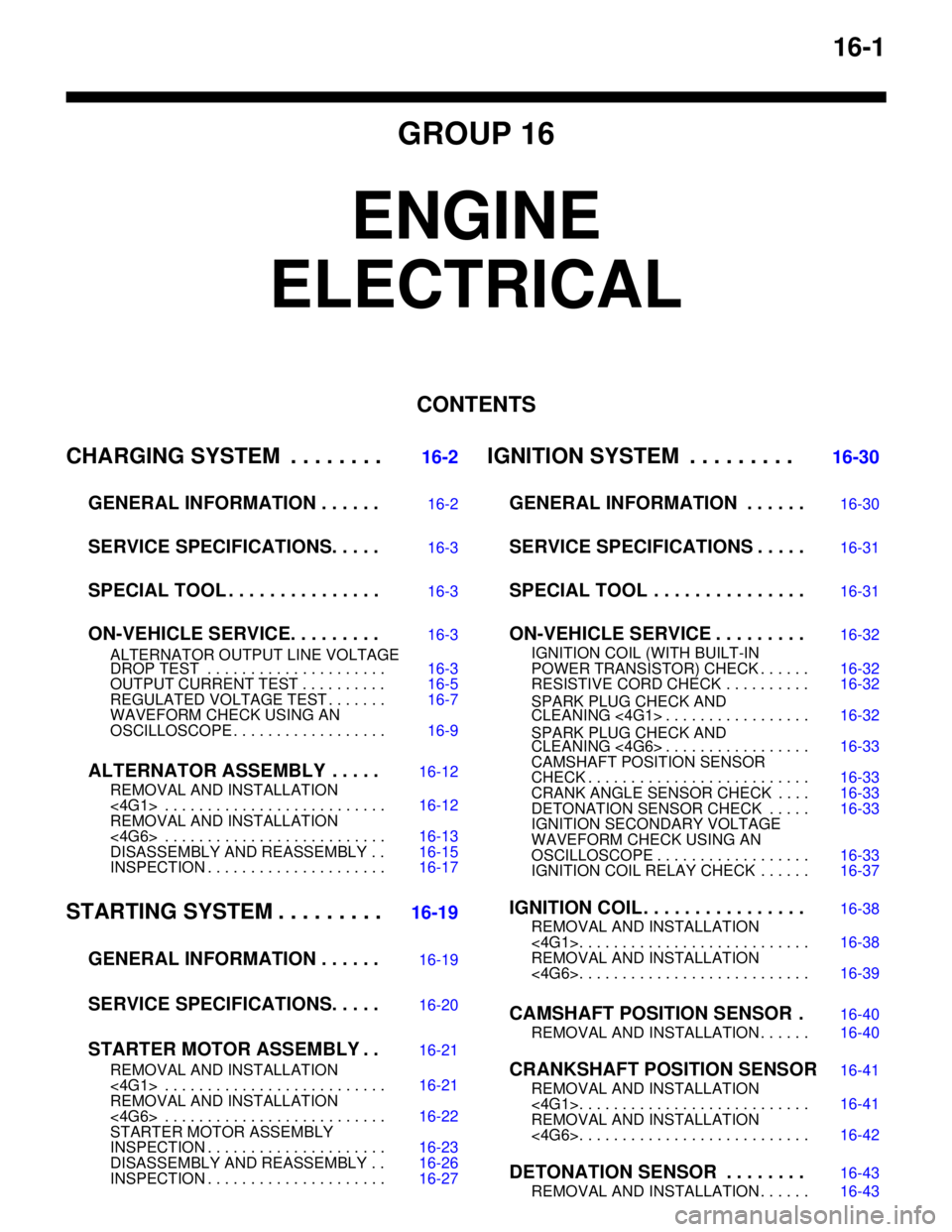
GROUP 16
ENGINE
ELECTRICAL
CONTENTS
CHARGING SYSTEM . . . . . . . .
16-2
GENERAL INFORMATION . . . . . .
16-2
SERVICE SPECIFICATIONS. . . . .16-3
SPECIAL TOOL . . . . . . . . . . . . . . .16-3
ON-VEHICLE SERVICE. . . . . . . . .16-3
ALTERNATOR OUTPUT LINE VOLTAGE
DROP TEST . . . . . . . . . . . . . . . . . . . . . 16-3
OUTPUT CURRENT TEST . . . . . . . . . . 16-5
REGULATED VOLTAGE TEST . . . . . . . 16-7
WAVEFORM CHECK USING AN
OSCILLOSCOPE . . . . . . . . . . . . . . . . . . 16-9
ALTERNATOR ASSEMBLY . . . . .16-12
REMOVAL AND INSTALLATION
<4G1> . . . . . . . . . . . . . . . . . . . . . . . . . . 16-12
REMOVAL AND INSTALLATION
<4G6> . . . . . . . . . . . . . . . . . . . . . . . . . . 16-13
DISASSEMBLY AND REASSEMBLY . . 16-15
INSPECTION . . . . . . . . . . . . . . . . . . . . . 16-17
STARTING SYSTEM . . . . . . . . .16-19
GENERAL INFORMATION . . . . . .
16-19
SERVICE SPECIFICATIONS. . . . .16-20
STARTER MOTOR ASSEMBLY . .16-21
REMOVAL AND INSTALLATION
<4G1> . . . . . . . . . . . . . . . . . . . . . . . . . . 16-21
REMOVAL AND INSTALLATION
<4G6> . . . . . . . . . . . . . . . . . . . . . . . . . . 16-22
STARTER MOTOR ASSEMBLY
INSPECTION . . . . . . . . . . . . . . . . . . . . . 16-23
DISASSEMBLY AND REASSEMBLY . . 16-26
INSPECTION . . . . . . . . . . . . . . . . . . . . . 16-27
IGNITION SYSTEM . . . . . . . . . 16-30
GENERAL INFORMATION . . . . . .
16-30
SERVICE SPECIFICATIONS . . . . .16-31
SPECIAL TOOL . . . . . . . . . . . . . . .16-31
ON-VEHICLE SERVICE . . . . . . . . .16-32
IGNITION COIL (WITH BUILT-IN
POWER TRANSISTOR) CHECK . . . . . . 16-32
RESISTIVE CORD CHECK . . . . . . . . . . 16-32
SPARK PLUG CHECK AND
CLEANING <4G1> . . . . . . . . . . . . . . . . . 16-32
SPARK PLUG CHECK AND
CLEANING <4G6> . . . . . . . . . . . . . . . . . 16-33
CAMSHAFT POSITION SENSOR
CHECK . . . . . . . . . . . . . . . . . . . . . . . . . . 16-33
CRANK ANGLE SENSOR CHECK . . . . 16-33
DETONATION SENSOR CHECK . . . . . 16-33
IGNITION SECONDARY VOLTAGE
WAVEFORM CHECK USING AN
OSCILLOSCOPE . . . . . . . . . . . . . . . . . . 16-33
IGNITION COIL RELAY CHECK . . . . . . 16-37
IGNITION COIL . . . . . . . . . . . . . . . .16-38
REMOVAL AND INSTALLATION
<4G1>. . . . . . . . . . . . . . . . . . . . . . . . . . . 16-38
REMOVAL AND INSTALLATION
<4G6>. . . . . . . . . . . . . . . . . . . . . . . . . . . 16-39
CAMSHAFT POSITION SENSOR .16-40
REMOVAL AND INSTALLATION . . . . . . 16-40
CRANKSHAFT POSITION SENSOR16-41
REMOVAL AND INSTALLATION
<4G1>. . . . . . . . . . . . . . . . . . . . . . . . . . . 16-41
REMOVAL AND INSTALLATION
<4G6>. . . . . . . . . . . . . . . . . . . . . . . . . . . 16-42
DETONATION SENSOR . . . . . . . .16-43
REMOVAL AND INSTALLATION . . . . . . 16-43
Page 81 of 788
CHARGING SYSTEM
ENGINE ELECTRICAL16-17
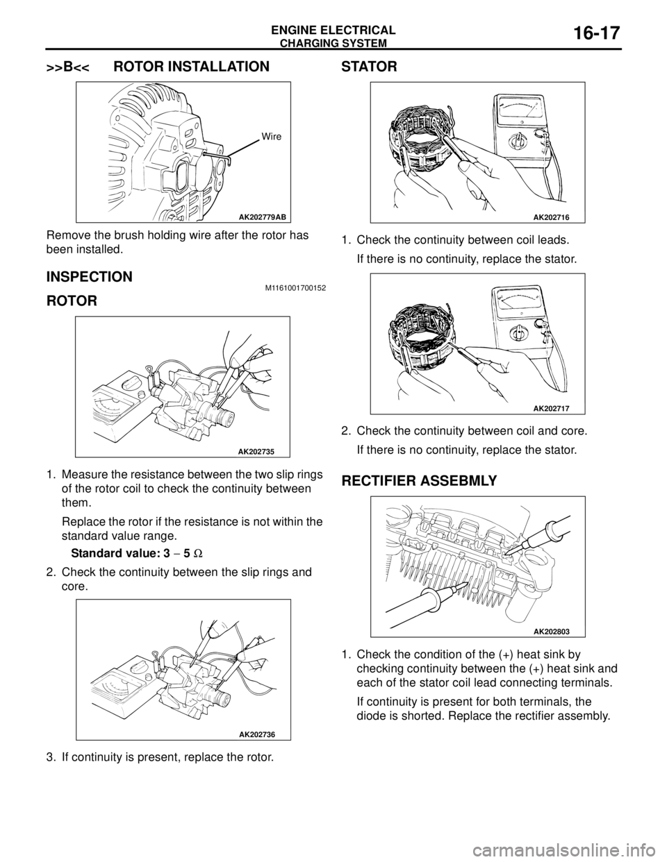
>>B<< ROTOR INSTALLATION
Remove the brush holding wire after the rotor has
been installed.
INSPECTION M1161001700152
ROTOR
1. Measure the resistance between the two slip rings
of the rotor coil to check the continuity between
them.
Replace the rotor if the resistance is not within the
standard value range.
Standard value: 3 − 5 Ω
2. Check the continuity between the slip rings and
core.
3. If continuity is present, replace the rotor.
STATOR
1. Check the continuity between coil leads.
If there is no continuity, replace the stator.
2. Check the continuity between coil and core.
If there is no continuity, replace the stator.
RECTIFIER ASSEBMLY
1. Check the condition of the (+) heat sink by
checking continuity between the (+) heat sink and
each of the stator coil lead connecting terminals.
If continuity is present for both terminals, the
diode is shorted. Replace the rectifier assembly.
AK202779
Wire
AB
AK202735
AK202736
AK202716
AK202717
AK202803