clutch MITSUBISHI LANCER 2005 Workshop Manual
[x] Cancel search | Manufacturer: MITSUBISHI, Model Year: 2005, Model line: LANCER, Model: MITSUBISHI LANCER 2005Pages: 788, PDF Size: 45.98 MB
Page 1 of 788
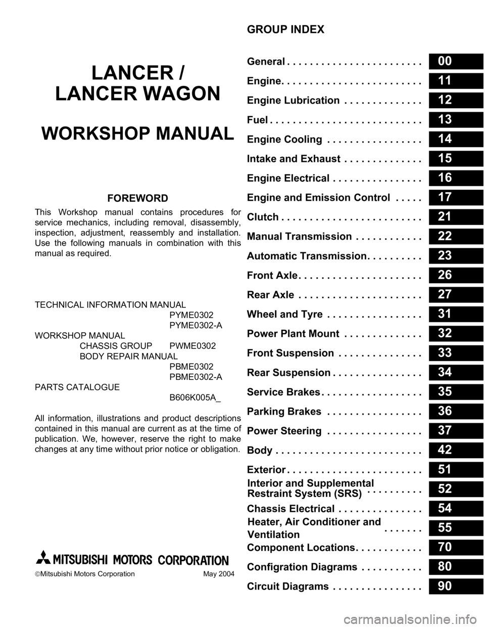
GROUP INDEX
00General . . . . . . . . . . . . . . . . . . . . . . . .
11Engine. . . . . . . . . . . . . . . . . . . . . . . . .
12Engine Lubrication . . . . . . . . . . . . . .
13Fuel . . . . . . . . . . . . . . . . . . . . . . . . . . .
14Engine Cooling . . . . . . . . . . . . . . . . .
15Intake and Exhaust . . . . . . . . . . . . . .
16Engine Electrical . . . . . . . . . . . . . . . .
17Engine and Emission Control . . . . .
21Clutch . . . . . . . . . . . . . . . . . . . . . . . . .
22Manual Transmission . . . . . . . . . . . .
23Automatic Transmission. . . . . . . . . .
26Front Axle . . . . . . . . . . . . . . . . . . . . . .
27Rear Axle . . . . . . . . . . . . . . . . . . . . . .
31Wheel and Tyre . . . . . . . . . . . . . . . . .
32Power Plant Mount . . . . . . . . . . . . . .
33Front Suspension . . . . . . . . . . . . . . .
34Rear Suspension . . . . . . . . . . . . . . . .
35Service Brakes . . . . . . . . . . . . . . . . . .
36Parking Brakes . . . . . . . . . . . . . . . . .
37Power Steering . . . . . . . . . . . . . . . . .
42Body . . . . . . . . . . . . . . . . . . . . . . . . . .
51Exterior . . . . . . . . . . . . . . . . . . . . . . . .
52 . . . . . . . . . .
54Chassis Electrical . . . . . . . . . . . . . . .
55 . . . . . . .
70Component Locations. . . . . . . . . . . .
80Configration Diagrams . . . . . . . . . . .
90Circuit Diagrams . . . . . . . . . . . . . . . .
LANCER /
LANCER WAGON
WORKSHOP MANUAL
FOREWORD
This Workshop manual contains procedures for
service mechanics, including removal, disassembly,
inspection, adjustment, reassembly and installation.
Use the following manuals in combination with this
manual as required.
TECHNICAL INFORMATION MANUAL
PYME0302
PYME0302-A
WORKSHOP MANUAL
CHASSIS GROUP PWME0302
BODY REPAIR MANUAL
PBME0302
PBME0302-A
PARTS CATALOGUE
B606K005A_
All information, illustrations and product descriptions
contained in this manual are current as at the time of
publication. We, however, reserve the right to make
changes at any time without prior notice or obligation.
Mitsubishi Motors Corporation May 2004
Heater, Air Conditioner and
Ventilation Interior and Supplemental
Restraint System (SRS)
Page 83 of 788
STARTING SYSTEM
ENGINE ELECTRICAL16-19
STARTING SYSTEM
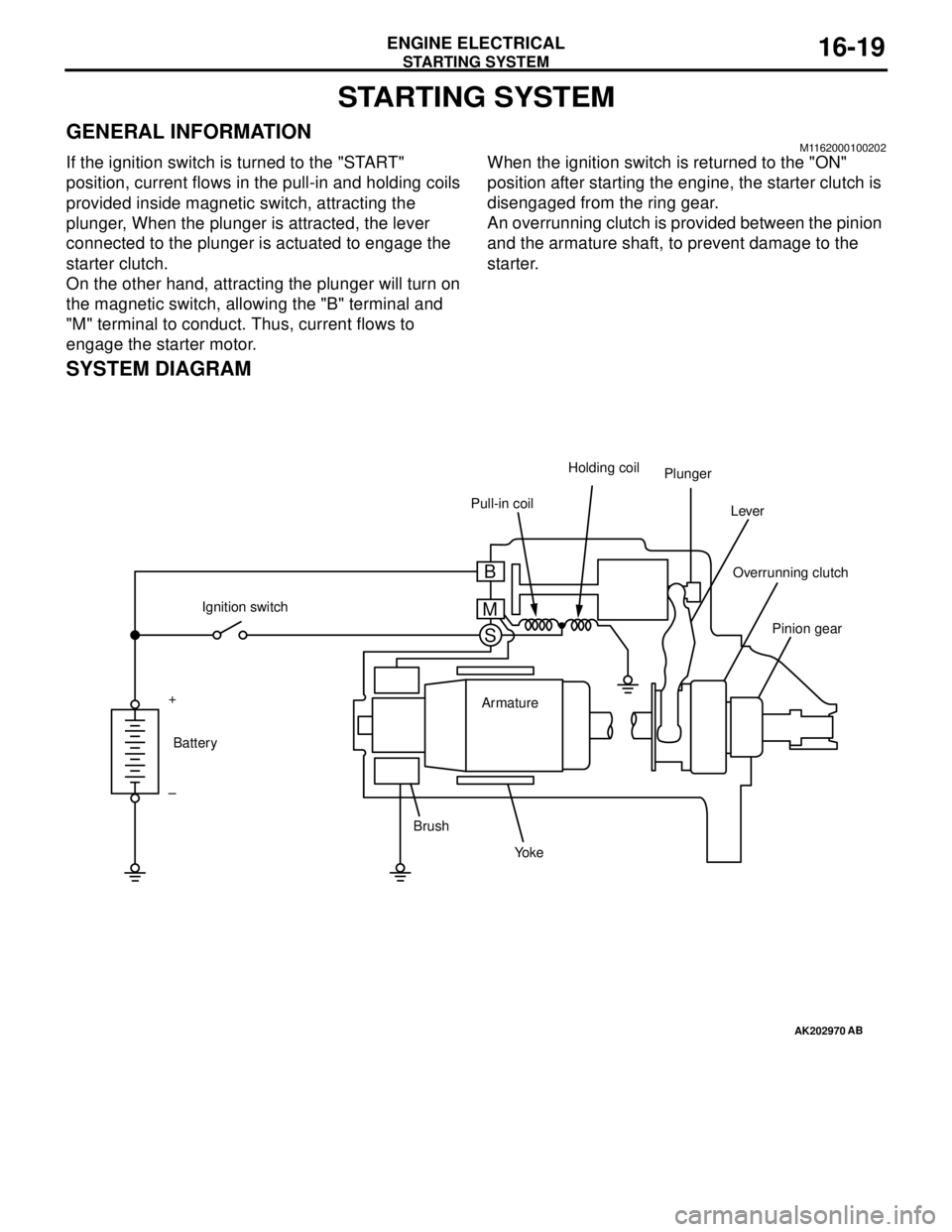
GENERAL INFORMATIONM1162000100202
If the ignition switch is turned to the "START"
position, current flows in the pull-in and holding coils
provided inside magnetic switch, attracting the
plunger, When the plunger is attracted, the lever
connected to the plunger is actuated to engage the
starter clutch.
On the other hand, attracting the plunger will turn on
the magnetic switch, allowing the "B" terminal and
"M" terminal to conduct. Thus, current flows to
engage the starter motor.When the ignition switch is returned to the "ON"
position after starting the engine, the starter clutch is
disengaged from the ring gear.
An overrunning clutch is provided between the pinion
and the armature shaft, to prevent damage to the
starter.
SYSTEM DIAGRAM
AK202970
Pull-in coilHolding coil
Plunger
Lever
Pinion gear Overrunning clutch
Yo k e BrushArmature Ignition switch
Battery +
–
AB
B
M
S
Page 86 of 788
STARTING SYSTEM
ENGINE ELECTRICAL16-22
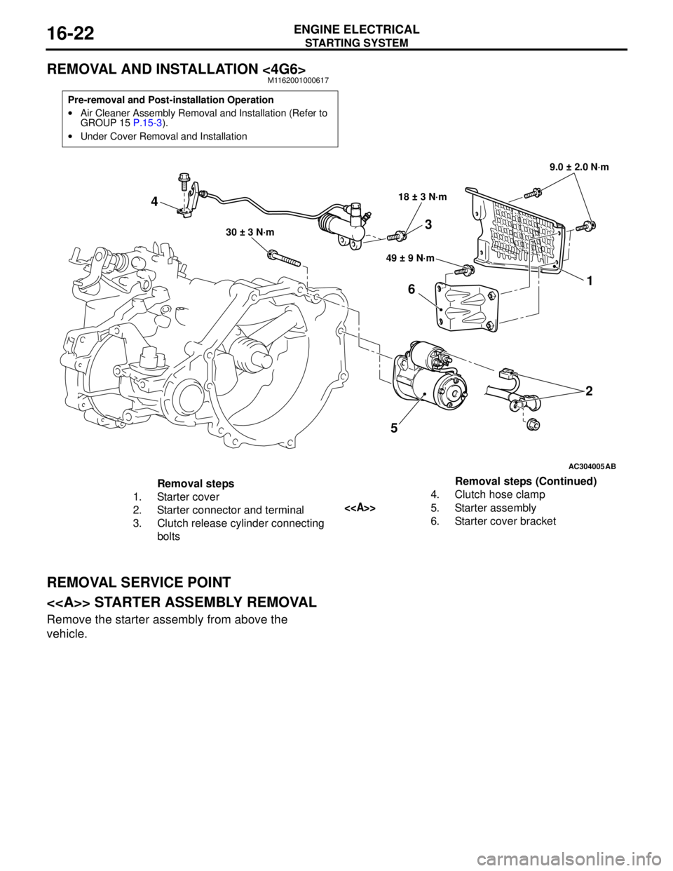
REMOVAL AND INSTALLATION <4G6>M1162001000617
REMOVAL SERVICE POINT
<> STARTER ASSEMBLY REMOVAL
Remove the starter assembly from above the
vehicle.
Pre-removal and Post-installation Operation
•Air Cleaner Assembly Removal and Installation (Refer to
GROUP 15 P.15-3).
•Under Cover Removal and Installation
AC304005
521
6
49 ± 9 N·m 18 ± 3 N·m9.0 ± 2.0 N·m
30 ± 3 N·m
AB
4
3
Removal steps
1. Starter cover
2. Starter connector and terminal
3. Clutch release cylinder connecting
bolts4. Clutch hose clamp
<>5. Starter assembly
6. Starter cover bracketRemoval steps (Continued)
Page 90 of 788
STARTING SYSTEM
ENGINE ELECTRICAL16-26
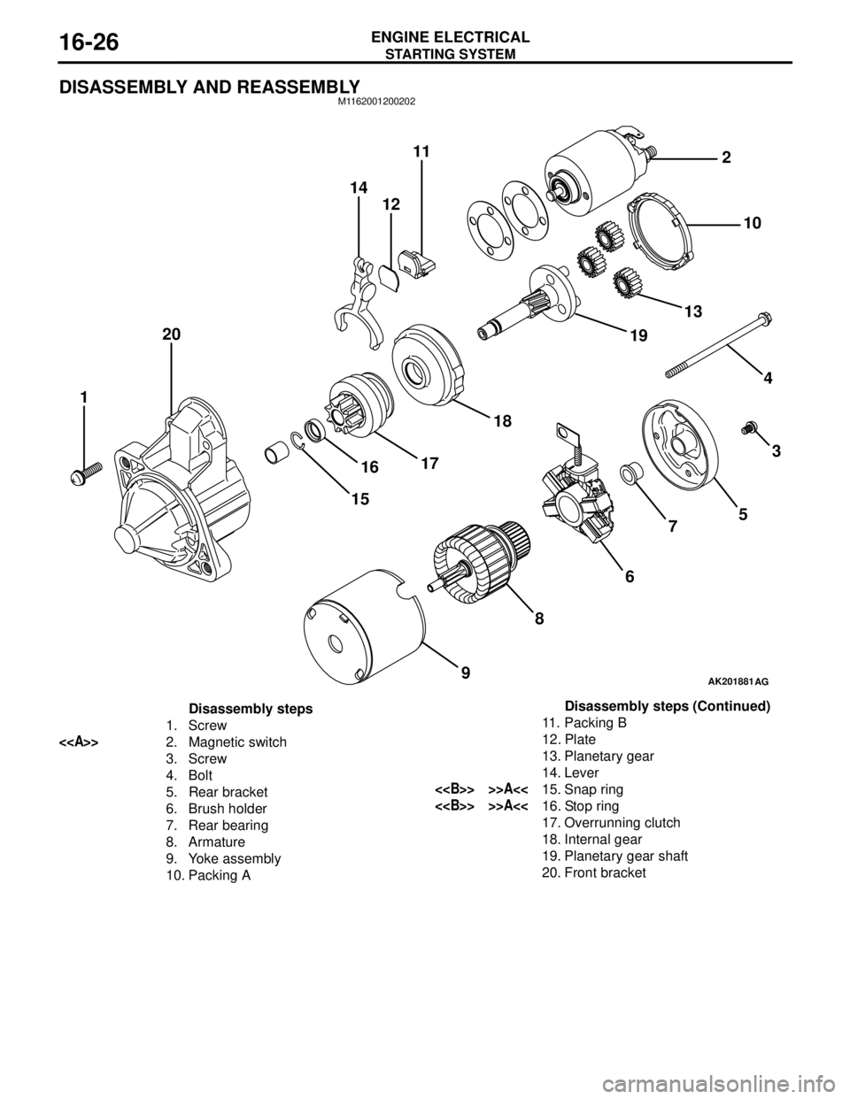
DISASSEMBLY AND REASSEMBLYM1162001200202
AK201881
14
1211
20
1
15161718191310 2
4
3
5
7
6
8
9
AG
Disassembly steps
1. Screw
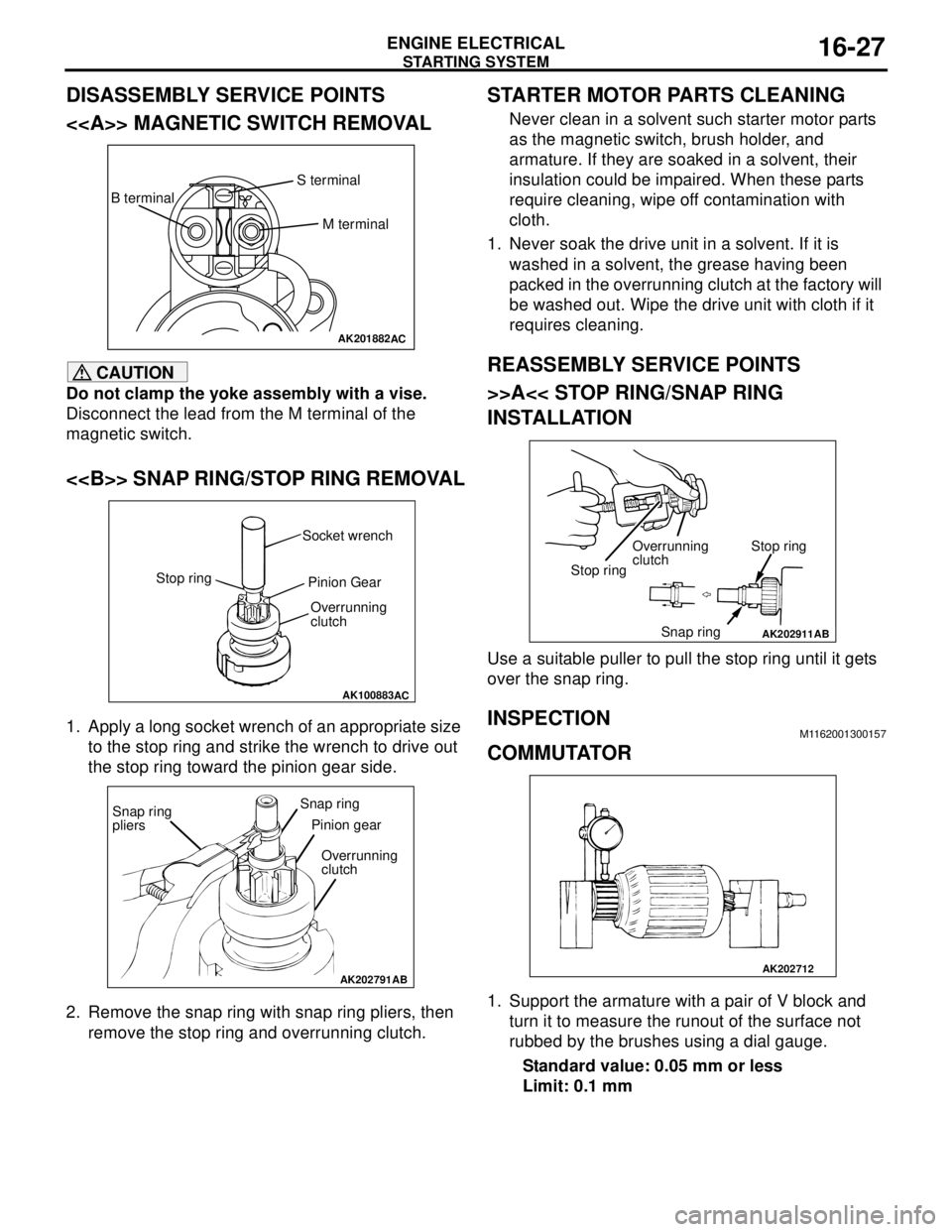
<>2. Magnetic switch
3. Screw
4. Bolt
5. Rear bracket
6. Brush holder
7. Rear bearing
8. Armature
9. Yoke assembly
10. Packing A11. Packing B
12. Plate
13. Planetary gear
14. Lever
<> >>A<<15. Snap ring
<> >>A<<16. Stop ring
17. Overrunning clutch
18. Internal gear
19. Planetary gear shaft
20. Front bracketDisassembly steps (Continued)
Page 91 of 788
Page 92 of 788
STARTING SYSTEM
ENGINE ELECTRICAL16-28
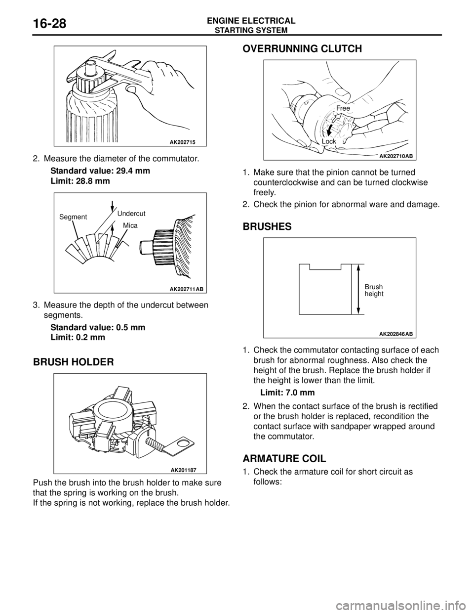
2. Measure the diameter of the commutator.
Standard value: 29.4 mm
Limit: 28.8 mm
3. Measure the depth of the undercut between
segments.
Standard value: 0.5 mm
Limit: 0.2 mm
BRUSH HOLDER
Push the brush into the brush holder to make sure
that the spring is working on the brush.
If the spring is not working, replace the brush holder.
OVERRUNNING CLUTCH
1. Make sure that the pinion cannot be turned
counterclockwise and can be turned clockwise
freely.
2. Check the pinion for abnormal ware and damage.
BRUSHES
1. Check the commutator contacting surface of each
brush for abnormal roughness. Also check the
height of the brush. Replace the brush holder if
the height is lower than the limit.
Limit: 7.0 mm
2. When the contact surface of the brush is rectified
or the brush holder is replaced, recondition the
contact surface with sandpaper wrapped around
the commutator.
ARMATURE COIL
1. Check the armature coil for short circuit as
follows:
AK202715
AK202711
SegmentUndercut
Mica
AB
AK201187
AK202710
Free
Lock
AB
AK202846
Brush
height
AB
Page 127 of 788

21-1
GROUP 21
CLUTCH
CONTENTS
CLUTCH . . . . . . . . . . . . . . . . . . . . . . . . . . . . . . . . . . . . . . . . . . .21A
CLUTCH OVERHAUL . . . . . . . . . . . . . . . . . . . . . . . . . . . . . . . . .21B
Page 448 of 788
COMBINATION METER ASSEMBLY
CHASSIS ELECTRICAL54A-60
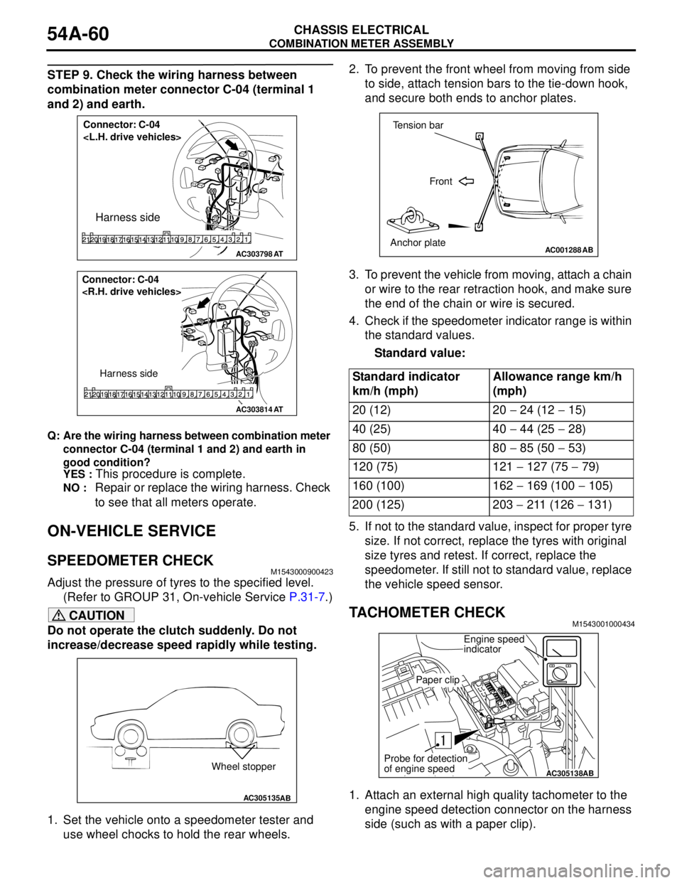
STEP 9. Check the wiring harness between
combination meter connector C-04 (terminal 1
and 2) and earth.
Q: Are the wiring harness between combination meter
connector C-04 (terminal 1 and 2) and earth in
good condition?
YES :
This procedure is complete.
NO : Repair or replace the wiring harness. Check
to see that all meters operate.
ON-VEHICLE SERVICE
SPEEDOMETER CHECKM1543000900423
Adjust the pressure of tyres to the specified level.
(Refer to GROUP 31, On-vehicle Service P.31-7.)
CAUTION
Do not operate the clutch suddenly. Do not
increase/decrease speed rapidly while testing.
1. Set the vehicle onto a speedometer tester and
use wheel chocks to hold the rear wheels.2. To prevent the front wheel from moving from side
to side, attach tension bars to the tie-down hook,
and secure both ends to anchor plates.
3. To prevent the vehicle from moving, attach a chain
or wire to the rear retraction hook, and make sure
the end of the chain or wire is secured.
4. Check if the speedometer indicator range is within
the standard values.
Standard value:
5. If not to the standard value, inspect for proper tyre
size. If not correct, replace the tyres with original
size tyres and retest. If correct, replace the
speedometer. If still not to standard value, replace
the vehicle speed sensor.
TACHOMETER CHECKM1543001000434
1. Attach an external high quality tachometer to the
engine speed detection connector on the harness
side (such as with a paper clip).
AC303798
Connector: C-04
Harness side
AT
AC303814
Connector: C-04
Harness side
AT
AC305135AB
Wheel stopper
Standard indicator
km/h (mph)Allowance range km/h
(mph)
20 (12) 20 − 24 (12 − 15)
40 (25) 40 − 44 (25 − 28)
80 (50) 80 − 85 (50 − 53)
120 (75) 121 − 127 (75 − 79)
160 (100) 162 − 169 (100 − 105)
200 (125) 203 − 211 (126 − 131)
AC001288
Tension bar
Front
Anchor plate
AB
AC305138AB
Engine speed
indicator
Paper clip
Probe for detection
of engine speed
Page 486 of 788
55-2
ON-VEHICLE SERVICE . . . . . . . . . . .55-69
SIGHT GLASS REFRIGERANT
LEVEL TEST . . . . . . . . . . . . . . . . . . . . . . . . 55-69
MAGNETIC CLUTCH TEST . . . . . . . . . . . . 55-69
COMPRESSOR DRIVE BELT
ADJUSTMENT . . . . . . . . . . . . . . . . . . . . . . 55-69
DUAL PRESSURE SWITCH CHECK . . . . . 55-69
CHARGING . . . . . . . . . . . . . . . . . . . . . . . . . 55-70
CORRECTING LOW REFRIGERANT LEVEL
IN CASE THE SERVICE CAN IN USED. . . 55-72
DISCHARGING SYSTEM . . . . . . . . . . . . . . 55-72
REFILLING OF OIL IN THE A/C
SYSTEM . . . . . . . . . . . . . . . . . . . . . . . . . . . 55-72
PERFORMANCE TEST . . . . . . . . . . . . . . . 55-73
REFRIGERANT LEAK REPAIR
PROCEDURE . . . . . . . . . . . . . . . . . . . . . . . 55-74
COMPRESSOR NOISE CHECK . . . . . . . . 55-74
POWER RELAY CHECK . . . . . . . . . . . . . . 55-75
IDLE-UP OPERATION CHECK . . . . . . . . . 55-76
CLEAN AIR FILTER REPLACEMENT
PROCEDURE . . . . . . . . . . . . . . . . . . . . . . . 55-76
HEATER CONTROL ASSEMBLY AND A/C
SWITCH . . . . . . . . . . . . . . . . . . . . . . .55-77
REMOVAL AND INSTALLATION . . . . . . . . 55-77
INSPECTION . . . . . . . . . . . . . . . . . . . . . . . 55-79
DISASSEMBLY AND REASSEMBLY . . . . . 55-79
HEATER UNIT, HEATER CORE,
BLOWER ASSEMBLY AND
EVAPORATOR UNIT* . . . . . . . . . . . .55-81
REMOVAL AND INSTALLATION . . . . . . . . 55-81
HEATER UNIT . . . . . . . . . . . . . . . . . . . . . . 55-82
DISASSEMBLY AND REASSEMBLY
DISASSEMBLY AND ASSEMBLY
BLOWER ASSEMBLY . . . . . . . . . . . . . . . . 55-84
DISASSEMBLY AND REASSEMBLY . . . . . 55-84
BLOWERMOTOR, RESISTOR AND
OUTSIDE/INSIDE AIR SELECTION
DAMPER CONTROL MOTOR . . . . . .55-85
REMOVAL AND INSTALLATION . . . . . . . . 55-85
INSPECTION . . . . . . . . . . . . . . . . . . . . . . . . 55-86
EVAPORATOR ASSEMBLY . . . . . . .55-88
REMOVAL AND INSTALLATION
REMOVAL AND INSTALLATION
INSPECTION . . . . . . . . . . . . . . . . . . . . . . . . 55-90
COMPRESSOR ASSEMBLY AND
TENSION PULLEY . . . . . . . . . . . . . . .55-91
REMOVAL AND INSTALLATION . . . . . . . . 55-91
INSPECTION . . . . . . . . . . . . . . . . . . . . . . . . 55-93
DISASSEMBLY AND REASSEMBLY . . . . . 55-94
INSPECTION . . . . . . . . . . . . . . . . . . . . . . . . 55-95
CONDENSER AND CONDENSER
FAN MOTOR . . . . . . . . . . . . . . . . . . . .55-96
REMOVAL AND INSTALLATION . . . . . . . . 55-96
INSPECTION . . . . . . . . . . . . . . . . . . . . . . . . 55-97
REFRIGERANT LINE . . . . . . . . . . . . .55-98
REMOVAL AND INSTALLATION
REMOVAL AND INSTALLATION
DUCTS . . . . . . . . . . . . . . . . . . . . . . . .55-101
REMOVAL AND INSTALLATION . . . . . . . . 55-101
VENTILATORS . . . . . . . . . . . . . . . . . .55-102
REMOVAL AND INSTALLATION . . . . . . . . 55-102
Page 487 of 788

SERVICE SPECIFICATIONS
HEATER, AIR CONDITIONER AND VENTILATION55-3
SERVICE SPECIFICATIONS
M1552000300292
LUBRICANTS
M1552000400299
ItemStandard value
Idle speed r/min 750 ± 100
Idle-up speed r/min 850 ± 100
Resistor (for blower motor) ΩLO 2.54
ML 1.24
MH 0.6
Air gap (magnetic clutch) mm 0.3 − 0.5
Item Specified lubricant Quantity
Compressor refrigerant unit lubricant SUN PAG 56 1300, 1600 140 mL
2000 120 mL
Each connection of refrigerant line SUN PAG 56 As required
Refrigerant R134a (HFC-134a) 480 − 520 g