diagram MITSUBISHI LANCER 2005 Workshop Manual
[x] Cancel search | Manufacturer: MITSUBISHI, Model Year: 2005, Model line: LANCER, Model: MITSUBISHI LANCER 2005Pages: 788, PDF Size: 45.98 MB
Page 1 of 788
GROUP INDEX
00General . . . . . . . . . . . . . . . . . . . . . . . .
11Engine. . . . . . . . . . . . . . . . . . . . . . . . .
12Engine Lubrication . . . . . . . . . . . . . .
13Fuel . . . . . . . . . . . . . . . . . . . . . . . . . . .
14Engine Cooling . . . . . . . . . . . . . . . . .
15Intake and Exhaust . . . . . . . . . . . . . .
16Engine Electrical . . . . . . . . . . . . . . . .
17Engine and Emission Control . . . . .
21Clutch . . . . . . . . . . . . . . . . . . . . . . . . .
22Manual Transmission . . . . . . . . . . . .
23Automatic Transmission. . . . . . . . . .
26Front Axle . . . . . . . . . . . . . . . . . . . . . .
27Rear Axle . . . . . . . . . . . . . . . . . . . . . .
31Wheel and Tyre . . . . . . . . . . . . . . . . .
32Power Plant Mount . . . . . . . . . . . . . .
33Front Suspension . . . . . . . . . . . . . . .
34Rear Suspension . . . . . . . . . . . . . . . .
35Service Brakes . . . . . . . . . . . . . . . . . .
36Parking Brakes . . . . . . . . . . . . . . . . .
37Power Steering . . . . . . . . . . . . . . . . .
42Body . . . . . . . . . . . . . . . . . . . . . . . . . .
51Exterior . . . . . . . . . . . . . . . . . . . . . . . .
52 . . . . . . . . . .
54Chassis Electrical . . . . . . . . . . . . . . .
55 . . . . . . .
70Component Locations. . . . . . . . . . . .
80Configration Diagrams . . . . . . . . . . .
90Circuit Diagrams . . . . . . . . . . . . . . . .
LANCER /
LANCER WAGON
WORKSHOP MANUAL
FOREWORD
This Workshop manual contains procedures for
service mechanics, including removal, disassembly,
inspection, adjustment, reassembly and installation.
Use the following manuals in combination with this
manual as required.
TECHNICAL INFORMATION MANUAL
PYME0302
PYME0302-A
WORKSHOP MANUAL
CHASSIS GROUP PWME0302
BODY REPAIR MANUAL
PBME0302
PBME0302-A
PARTS CATALOGUE
B606K005A_
All information, illustrations and product descriptions
contained in this manual are current as at the time of
publication. We, however, reserve the right to make
changes at any time without prior notice or obligation.
Mitsubishi Motors Corporation May 2004
Heater, Air Conditioner and
Ventilation Interior and Supplemental
Restraint System (SRS)
Page 66 of 788
CHARGING SYSTEM
ENGINE ELECTRICAL16-2
CHARGING SYSTEM
GENERAL INFORMATIONM1161000100522
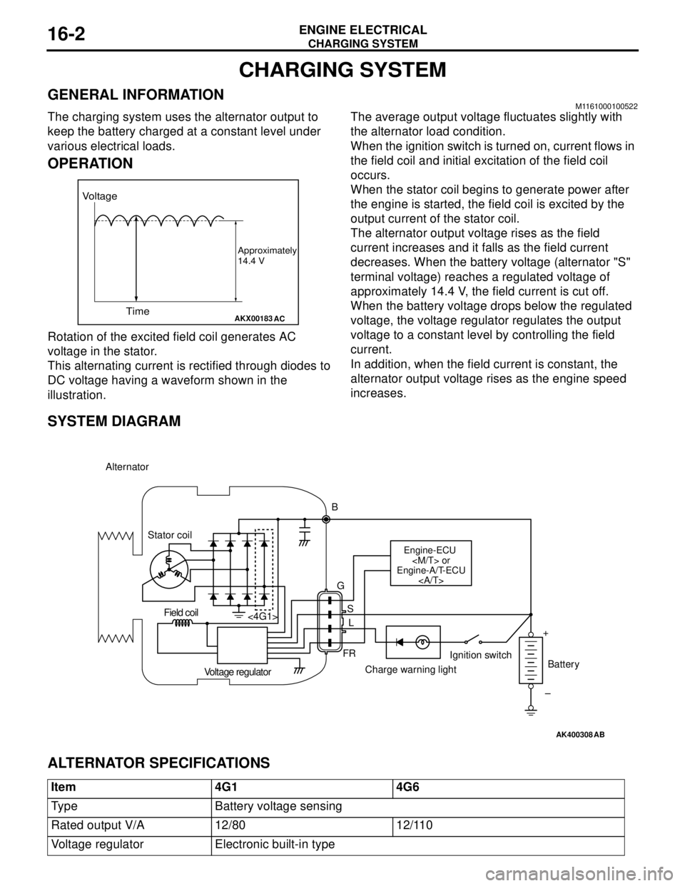
The charging system uses the alternator output to
keep the battery charged at a constant level under
various electrical loads.
OPERATION
Rotation of the excited field coil generates AC
voltage in the stator.
This alternating current is rectified through diodes to
DC voltage having a waveform shown in the
illustration.The average output voltage fluctuates slightly with
the alternator load condition.
When the ignition switch is turned on, current flows in
the field coil and initial excitation of the field coil
occurs.
When the stator coil begins to generate power after
the engine is started, the field coil is excited by the
output current of the stator coil.
The alternator output voltage rises as the field
current increases and it falls as the field current
decreases. When the battery voltage (alternator "S"
terminal voltage) reaches a regulated voltage of
approximately 14.4 V, the field current is cut off.
When the battery voltage drops below the regulated
voltage, the voltage regulator regulates the output
voltage to a constant level by controlling the field
current.
In addition, when the field current is constant, the
alternator output voltage rises as the engine speed
increases.
SYSTEM DIAGRAM
ALTERNATOR SPECIFICATIONS
AKX00183
Voltage
Time
Approximately
14.4 V
AC
AK400308
Alternator
B
Stator coil
Engine-ECU
Engine-A/T-ECU
G
S
L
FR <4G1>
Voltage regulatorCharge warning lightIgnition switch
Battery Field coil
+
–
AB
Item 4G1 4G6
Type Battery voltage sensing
Rated output V/A 12/80 12/110
Voltage regulator Electronic built-in type
Page 83 of 788
STARTING SYSTEM
ENGINE ELECTRICAL16-19
STARTING SYSTEM
GENERAL INFORMATIONM1162000100202
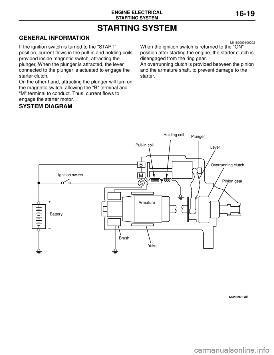
If the ignition switch is turned to the "START"
position, current flows in the pull-in and holding coils
provided inside magnetic switch, attracting the
plunger, When the plunger is attracted, the lever
connected to the plunger is actuated to engage the
starter clutch.
On the other hand, attracting the plunger will turn on
the magnetic switch, allowing the "B" terminal and
"M" terminal to conduct. Thus, current flows to
engage the starter motor.When the ignition switch is returned to the "ON"
position after starting the engine, the starter clutch is
disengaged from the ring gear.
An overrunning clutch is provided between the pinion
and the armature shaft, to prevent damage to the
starter.
SYSTEM DIAGRAM
AK202970
Pull-in coilHolding coil
Plunger
Lever
Pinion gear Overrunning clutch
Yo k e BrushArmature Ignition switch
Battery +
–
AB
B
M
S
Page 94 of 788
IGNITION SYSTEM
ENGINE ELECTRICAL16-30
IGNITION SYSTEM
GENERAL INFORMATIONM1163000100294
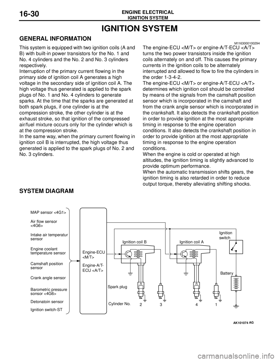
This system is equipped with two ignition coils (A and
B) with built-in power transistors for the No. 1 and
No. 4 cylinders and the No. 2 and No. 3 cylinders
respectively.
Interruption of the primary current flowing in the
primary side of ignition coil A generates a high
voltage in the secondary side of ignition coil A. The
high voltage thus generated is applied to the spark
plugs of No. 1 and No. 4 cylinders to generate
sparks. At the time that the sparks are generated at
both spark plugs, if one cylinder is at the
compression stroke, the other cylinder is at the
exhaust stroke, so that ignition of the compressed
air/fuel mixture occurs only for the cylinder which is
at the compression stroke.
In the same way, when the primary current flowing in
ignition coil B is interrupted, the high voltage thus
generated is applied to the spark plugs of No. 2 and
No. 3 cylinders.The engine-ECU
turns the two power transistors inside the ignition
coils alternately on and off. This causes the primary
currents in the ignition coils to be alternately
interrupted and allowed to flow to fire the cylinders in
the order 1-3-4-2.
The engine-ECU
determines which ignition coil should be controlled
by means of the signals from the camshaft position
sensor which is incorporated in the camshaft and
from the crank angle sensor which is incorporated in
the crankshaft. It also detects the crankshaft position
in order to provide ignition at the most appropriate
timing in response to the engine operation
conditions. It also detects the crankshaft position in
order to provide ignition at the most appropriate
timing in response to the engine operation
conditions.
When the engine is cold or operated at high
altitudes, the ignition timing is slightly advanced to
provide optimum performance.
When the automatic transmission shifts gears, the
ignition timing is also retarded in order to reduce
output torque, thereby alleviating shifting shocks.
SYSTEM DIAGRAM
AK101074
Air flow sensor
<4G6> MAP sensor <4G1>
Intake air temperatur
sensor
Engine coolant
temperature sensor
Camshaft position
sensor
Crank angle sensor
Barometric pressure
sonsor <4G6>
Detonatoin sensor
Ignition switch-STEngine-A/T-
ECU Engine-ECU
Cylinder No.
23 4
AG
1 Spark plugIgnition coil AIgnition
switch
Battery
Page 109 of 788
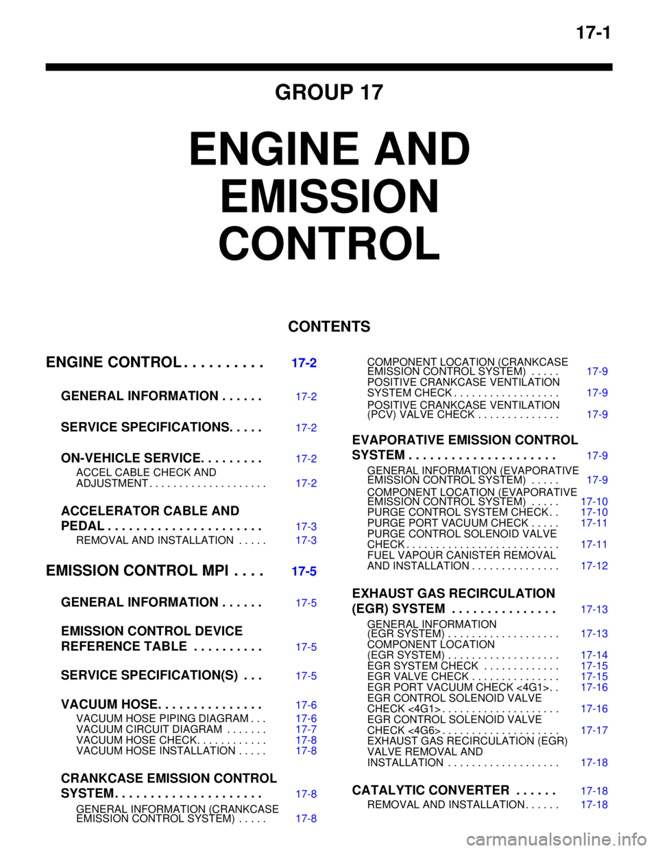
17-1
GROUP 17
ENGINE AND
EMISSION
CONTROL
CONTENTS
ENGINE CONTROL . . . . . . . . . .
17-2
GENERAL INFORMATION . . . . . .
17-2
SERVICE SPECIFICATIONS. . . . .17-2
ON-VEHICLE SERVICE. . . . . . . . .17-2
ACCEL CABLE CHECK AND
ADJUSTMENT . . . . . . . . . . . . . . . . . . . . 17-2
ACCELERATOR CABLE AND
PEDAL . . . . . . . . . . . . . . . . . . . . . .
17-3
REMOVAL AND INSTALLATION . . . . . 17-3
EMISSION CONTROL MPI . . . .17-5
GENERAL INFORMATION . . . . . .
17-5
EMISSION CONTROL DEVICE
REFERENCE TABLE . . . . . . . . . .
17-5
SERVICE SPECIFICATION(S) . . .17-5
VACUUM HOSE. . . . . . . . . . . . . . .17-6
VACUUM HOSE PIPING DIAGRAM . . . 17-6
VACUUM CIRCUIT DIAGRAM . . . . . . . 17-7
VACUUM HOSE CHECK. . . . . . . . . . . . 17-8
VACUUM HOSE INSTALLATION . . . . . 17-8
CRANKCASE EMISSION CONTROL
SYSTEM . . . . . . . . . . . . . . . . . . . . .
17-8
GENERAL INFORMATION (CRANKCASE
EMISSION CONTROL SYSTEM) . . . . . 17-8COMPONENT LOCATION (CRANKCASE
EMISSION CONTROL SYSTEM) . . . . . 17-9
POSITIVE CRANKCASE VENTILATION
SYSTEM CHECK . . . . . . . . . . . . . . . . . . 17-9
POSITIVE CRANKCASE VENTILATION
(PCV) VALVE CHECK . . . . . . . . . . . . . . 17-9
EVAPORATIVE EMISSION CONTROL
SYSTEM . . . . . . . . . . . . . . . . . . . . .
17-9
GENERAL INFORMATION (EVAPORATIVE
EMISSION CONTROL SYSTEM) . . . . . 17-9
COMPONENT LOCATION (EVAPORATIVE
EMISSION CONTROL SYSTEM) . . . . . 17-10
PURGE CONTROL SYSTEM CHECK . . 17-10
PURGE PORT VACUUM CHECK . . . . . 17-11
PURGE CONTROL SOLENOID VALVE
CHECK . . . . . . . . . . . . . . . . . . . . . . . . . . 17-11
FUEL VAPOUR CANISTER REMOVAL
AND INSTALLATION . . . . . . . . . . . . . . . 17-12
EXHAUST GAS RECIRCULATION
(EGR) SYSTEM . . . . . . . . . . . . . . .
17-13
GENERAL INFORMATION
(EGR SYSTEM) . . . . . . . . . . . . . . . . . . . 17-13
COMPONENT LOCATION
(EGR SYSTEM) . . . . . . . . . . . . . . . . . . . 17-14
EGR SYSTEM CHECK . . . . . . . . . . . . . 17-15
EGR VALVE CHECK . . . . . . . . . . . . . . . 17-15
EGR PORT VACUUM CHECK <4G1>. . 17-16
EGR CONTROL SOLENOID VALVE
CHECK <4G1> . . . . . . . . . . . . . . . . . . . . 17-16
EGR CONTROL SOLENOID VALVE
CHECK <4G6> . . . . . . . . . . . . . . . . . . . . 17-17
EXHAUST GAS RECIRCULATION (EGR)
VALVE REMOVAL AND
INSTALLATION . . . . . . . . . . . . . . . . . . . 17-18
CATALYTIC CONVERTER . . . . . .17-18
REMOVAL AND INSTALLATION . . . . . . 17-18
Page 114 of 788
EMISSION CONTROL
ENGINE AND EMISSION CONTROL17-6
VACUUM HOSE
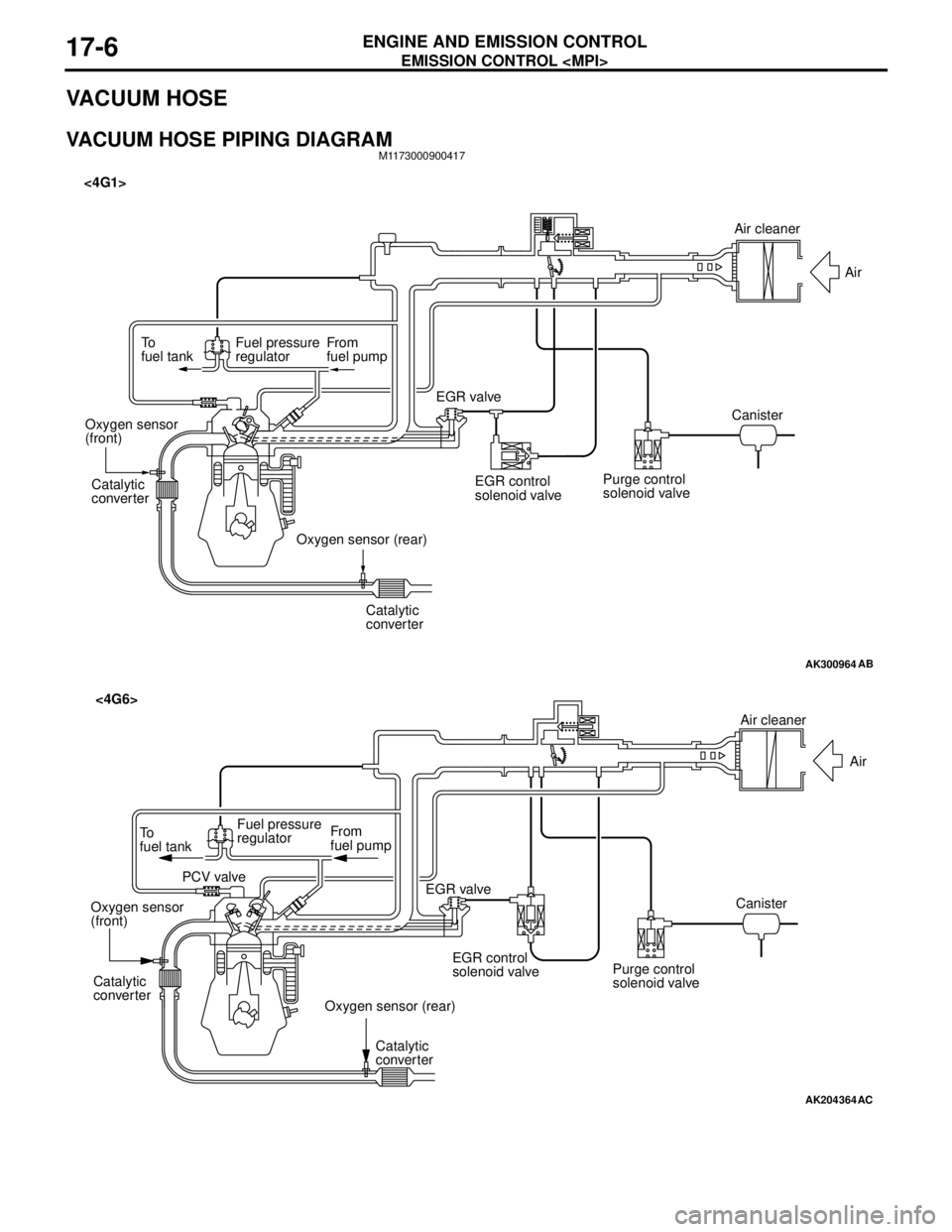
VACUUM HOSE PIPING DIAGRAMM1173000900417
AK300964
To
fuel tankFuel pressure
regulatorFrom
fuel pump
Catalytic
converter
Catalytic
converter Oxygen sensor
(front)
Oxygen sensor (rear)EGR valve <4G1>
EGR control
solenoid valvePurge control
solenoid valveCanisterAir
AB
Air cleaner
AK204364
AC
Air cleaner
Air
Canister
Purge control
solenoid valve EGR control
solenoid valve EGR valve From
fuel pump To
fuel tankFuel pressure
regulator
PCV valve
Oxygen sensor
(front)
Oxygen sensor (rear) Catalytic
converter
Catalytic
converter
<4G6>
Page 115 of 788
EMISSION CONTROL
ENGINE AND EMISSION CONTROL17-7
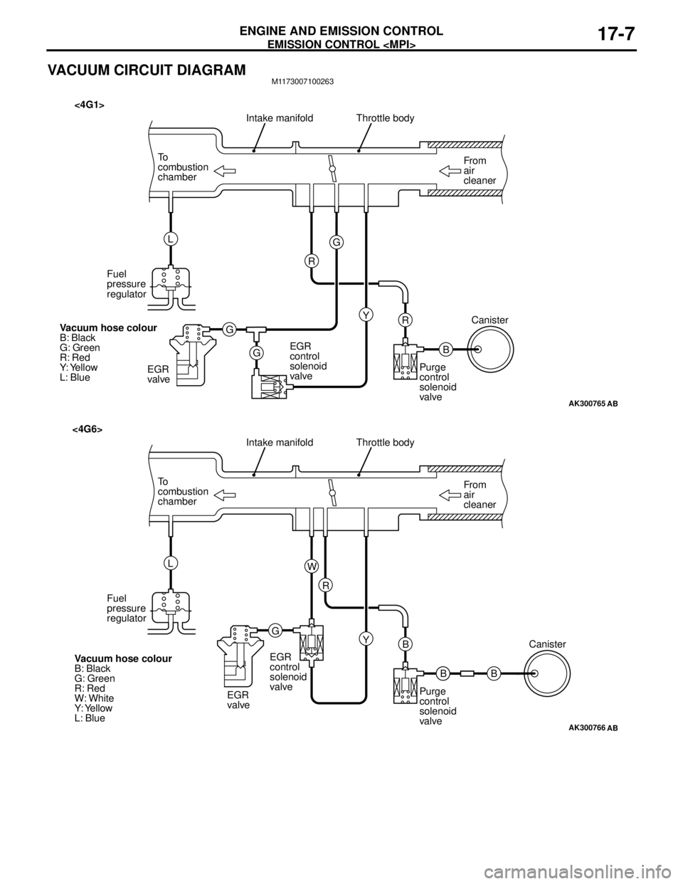
VACUUM CIRCUIT DIAGRAMM1173007100263
AK300765
From
air
cleaner To
combustion
chamberThrottle body
B R
AB
Intake manifold
Y G
G
GR L
Fuel
pressure
regulator
EGR
valveEGR
control
solenoid
valvePurge
control
solenoid
valveCanister
Vacuum hose colour
B: Black
G: Green
R: Red
Y: Yellow
L: Blue
<4G1>
AK300766
From
air
cleaner To
combustion
chamberThrottle body
B B
AB
Intake manifold
Y R
GW L
Fuel
pressure
regulator
EGR
valveEGR
control
solenoid
valve
Purge
control
solenoid
valveCanister
Vacuum hose colour
B: Black
G: Green
R: Red
W: White
Y: Yellow
L: Blue
<4G6>
B
Page 116 of 788
EMISSION CONTROL
ENGINE AND EMISSION CONTROL17-8
VACUUM HOSE CHECKM1173007300159
1. Using the piping diagram as a guide, check to be
sure that the vacuum hoses are correctly
connected.
2. Check the connection condition of the vacuum
hoses, (removed, loose, etc.) and check to be
sure that there are no bends or damage.
VACUUM HOSE INSTALLATIONM1173007200107
1. When connecting the vacuum hoses, they should
be securely inserted onto the nipples.
2. Connect the hoses correctly, using the vacuum
hose piping diagram as a guide.
CRANKCASE EMISSION CONTROL
SYSTEM
GENERAL INFORMATION (CRANKCASE
EMISSION CONTROL SYSTEM)
M1173005000237
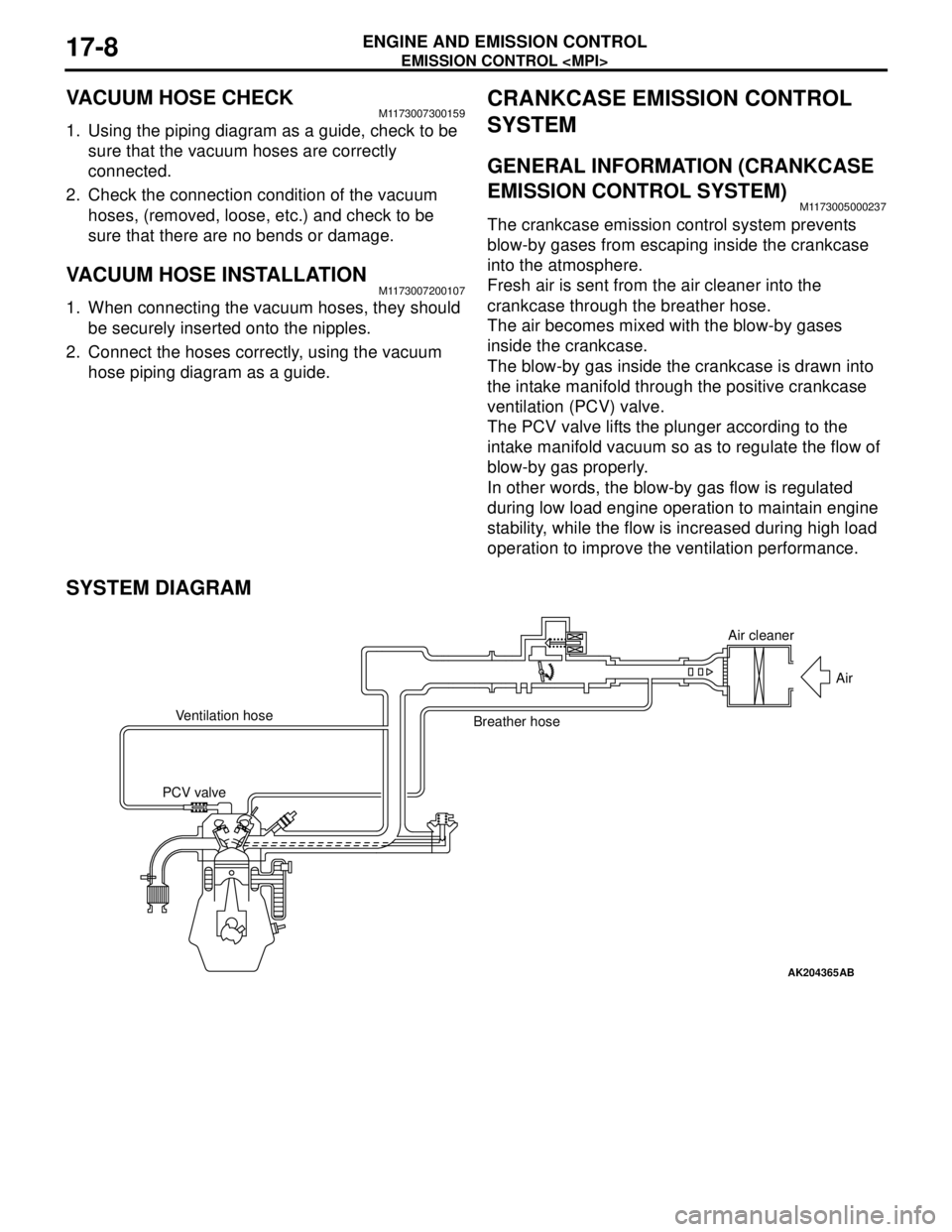
The crankcase emission control system prevents
blow-by gases from escaping inside the crankcase
into the atmosphere.
Fresh air is sent from the air cleaner into the
crankcase through the breather hose.
The air becomes mixed with the blow-by gases
inside the crankcase.
The blow-by gas inside the crankcase is drawn into
the intake manifold through the positive crankcase
ventilation (PCV) valve.
The PCV valve lifts the plunger according to the
intake manifold vacuum so as to regulate the flow of
blow-by gas properly.
In other words, the blow-by gas flow is regulated
during low load engine operation to maintain engine
stability, while the flow is increased during high load
operation to improve the ventilation performance.
SYSTEM DIAGRAM
AK204365
Air cleaner
Air
Ventilation hose
Breather hose
PCV valve
AB
Page 118 of 788
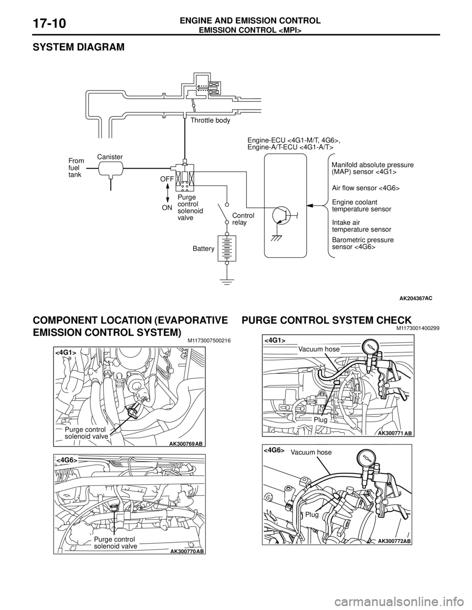
EMISSION CONTROL
ENGINE AND EMISSION CONTROL17-10
SYSTEM DIAGRAM
COMPONENT LOCATION (EVAPORATIVE
EMISSION CONTROL SYSTEM)
M1173007500216
PURGE CONTROL SYSTEM CHECKM1173001400299
AK204367AC
Throttle body
Canister
From
fuel
tank
OFF
ONPurge
control
solenoid
valveControl
relay
BatteryEngine-ECU <4G1-M/T, 4G6>,
Engine-A/T-ECU <4G1-A/T>
Air flow sensor <4G6>
Engine coolant
temperature sensor
Intake air
temperature sensor
Barometric pressure
sensor <4G6> Manifold absolute pressure
(MAP) sensor <4G1>
AK300769
<4G1>
AB
Purge control
solenoid valve
AK300770
<4G6>
AB
Purge control
solenoid valve
AK300771
<4G1>
AB
Plug
Vacuum hose
AK300772
<4G6>
AB
Plug
Vacuum hose
Page 121 of 788
EMISSION CONTROL
ENGINE AND EMISSION CONTROL17-13
EXHAUST GAS RECIRCULATION
(EGR) SYSTEM
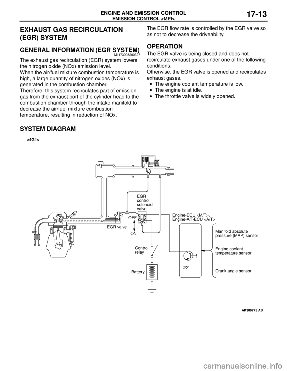
GENERAL INFORMATION (EGR SYSTEM)M1173005200327
The exhaust gas recirculation (EGR) system lowers
the nitrogen oxide (NOx) emission level.
When the air/fuel mixture combustion temperature is
high, a large quantity of nitrogen oxides (NOx) is
generated in the combustion chamber.
Therefore, this system recirculates part of emission
gas from the exhaust port of the cylinder head to the
combustion chamber through the intake manifold to
decrease the air/fuel mixture combustion
temperature, resulting in reduction of NOx.The EGR flow rate is controlled by the EGR valve so
as not to decrease the driveability.
OPERATION
The EGR valve is being closed and does not
recirculate exhaust gases under one of the following
conditions.
Otherwise, the EGR valve is opened and recirculates
exhaust gases.
•The engine coolant temperature is low.
•The engine is at idle.
•The throttle valve is widely opened.
SYSTEM DIAGRAM
AK300775
Manifold absolute
pressure (MAP) sensor Engine-ECU
Engine-A/T-ECU
Engine coolant
temperature sensor
Crank angle sensor EGR
control
solenoid
valve
EGR valveOFF
ON
Control
relay
Battery
AB
<4G1>