diagram MITSUBISHI LANCER 2005 Owner's Manual
[x] Cancel search | Manufacturer: MITSUBISHI, Model Year: 2005, Model line: LANCER, Model: MITSUBISHI LANCER 2005Pages: 788, PDF Size: 45.98 MB
Page 607 of 788
80-1
GROUP 80
CONFIGURATION
DIAGRAMS
CONTENTS
OVERALL CONFIGURATION
DIAGRAM. . . . . . . . . . . . . . . . . . . . . .80-2
OVERALL WIRING DIAGRAM
OVERALL WIRING DIAGRAM
OVERALL WIRING DIAGRAM
OVERALL WIRING DIAGRAM
ENGINE COMPARTMENT. . . . . . . . .80-6
ENGINE COMPARTMENT
ENGINE COMPARTMENT
ENGINE AND TRANSMISSION. . . . .80-8
ENGINE AND TRANSMISSION
<4G1-MPI (LHD) > . . . . . . . . . . . . . . . . . . . 80-8
ENGINE AND TRANSMISSION
<4G1-MPI (RHD) > . . . . . . . . . . . . . . . . . . . 80-10
ENGINE AND TRANSMISSION
<4G6-MPI (LHD) > . . . . . . . . . . . . . . . . . . . 80-12
ENGINE AND TRANSMISSION
<4G6-MPI (RHD) > . . . . . . . . . . . . . . . . . . . 80-14
DASH PANEL . . . . . . . . . . . . . . . . . . .80-16
DASH PANEL
DASH PANEL
FLOOR AND ROOF . . . . . . . . . . . . . .80-22
FLOOR AND ROOF
FLOOR AND ROOF
FLOOR AND ROOF
FLOOR AND ROOF
DOOR . . . . . . . . . . . . . . . . . . . . . . . . .80-26
DOOR
DOOR
TRUNK
(LUGGAGE COMPARTMENT). . . . . .80-28
TRUNK (LUGGAGE COMPARTMENT)
TRUNK (LUGGAGE COMPARTMENT)
TAILGATE. . . . . . . . . . . . . . . . . . . . . .80-30
TAILGATE
TAILGATE
Page 608 of 788

OVERALL CONFIGURATION DIAGRAM
CONFIGURATION DIAGRAMS80-2
OVERALL CONFIGURATION DIAGRAM
OVERALL WIRING DIAGRAM
NOTE: .
1. This illustration shows only major wiring harnesses.
2. *: also equipped at the right side.
AC301175
AB
Front wiring
harness (RH)Control wiring
harnessInstrument panel
wiring harnessRoof wiring
harnessFloor wiring
harness (RH)
Battery wiring
harnessFront wiring
harness (LH)Front door
wiring harness Floor wiring
harness (LH)Fuel wiring
harnessRear door
wiring harness
Front bumper
wiring harness
Rear bumper
wiring harness
**
Page 609 of 788

OVERALL CONFIGURATION DIAGRAM
CONFIGURATION DIAGRAMS80-3
OVERALL WIRING DIAGRAM
NOTE: .
1. This illustration shows only major wiring harnesses.
2. *: also equipped at the right side.
AC301176AB
Front wiring
harness (RH)Control wiring
harnessInstrument panel
wiring harnessRoof wiring
harnessFloor wiring
harness (RH)
Battery wiring
harnessFront wiring
harness (LH)Front door
wiring harness Floor wiring
harness (LH)Fuel wiring
harnessRear door
wiring harness
Front bumper
wiring harness
Rear bumper
wiring harness
**
Page 610 of 788
OVERALL CONFIGURATION DIAGRAM
CONFIGURATION DIAGRAMS80-4
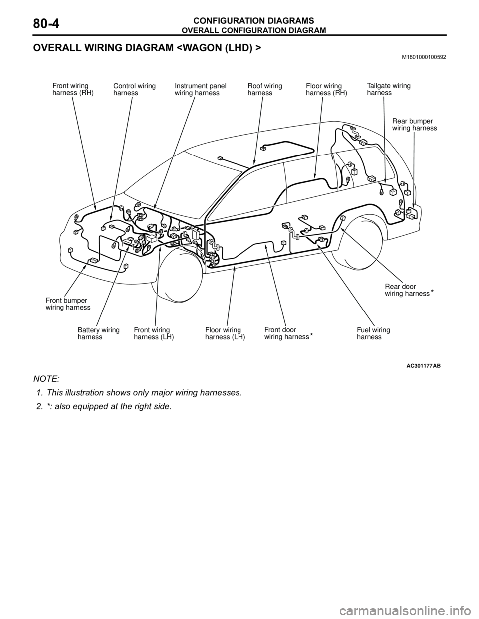
OVERALL WIRING DIAGRAM
NOTE: .
1. This illustration shows only major wiring harnesses.
2. *: also equipped at the right side.
AC301177AB
Front wiring
harness (RH)Control wiring
harnessInstrument panel
wiring harnessRoof wiring
harnessFloor wiring
harness (RH)
Battery wiring
harnessFront wiring
harness (LH)Front door
wiring harness Floor wiring
harness (LH)Fuel wiring
harnessRear door
wiring harness
Front bumper
wiring harness
Rear bumper
wiring harness
**
Tailgate wiring
harness
Page 611 of 788
OVERALL CONFIGURATION DIAGRAM
CONFIGURATION DIAGRAMS80-5
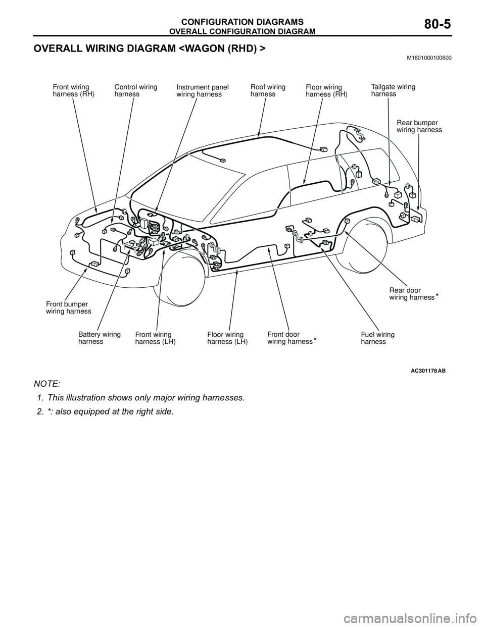
OVERALL WIRING DIAGRAM
NOTE: .
1. This illustration shows only major wiring harnesses.
2. *: also equipped at the right side.
AC301178AB
Front wiring
harness (RH)Control wiring
harnessInstrument panel
wiring harnessRoof wiring
harnessFloor wiring
harness (RH)
Battery wiring
harnessFront wiring
harness (LH)Front door
wiring harness Floor wiring
harness (LH)Fuel wiring
harnessRear door
wiring harness
Front bumper
wiring harness
Rear bumper
wiring harness
**
Tailgate wiring
harness
Page 612 of 788
ENGINE COMPARTMENT
CONFIGURATION DIAGRAMS80-6
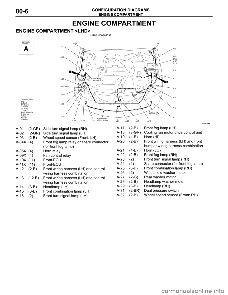
ENGINE COMPARTMENT
ENGINE COMPARTMENT
AC301122AB
A-02
A-03
A-04X
A-05X
A-09X
A-10X
A-11X
A-12
A-13
A-14
A-15
A-16
A-17
A-18 A-19 A-20 A-21Front wiring
harness (LH)
12Front wiring
harness (RH) A-01
A-32
A-31
A-29
A-28
A-27
A-26
A-25
A-23 A-24 A-22
1
Front bumper
wiring harness Connector colour
code
B : Black
BR : Brown
G : Green
GR : Gray
L : Blue
None : Milk white
O : Orange
R : Red
V : Violet
Y : Yellow
Connector
symbol
A
A-01 (2-GR) Side turn signal lamp (RH)
A-02 (2-GR) Side turn signal lamp (LH)
A-03 (2-B) Wheel speed sensor (Front: LH)
A-04X (4) Front fog lamp relay or spare connector
(for front fog lamp)
A-05X (4) Horn relay
A-09X (4) Fan control relay
A-10X (11) Front-ECU
A-11X (11) Front-ECU
A-12 (2-B) Front wiring harness (LH) and control
wiring harness combination
A-13 (12-B) Front wiring harness (LH) and control
wiring harness combination
A-14 (3-B) Headlamp (LH)
A-15 (6-B) Front combination lamp (LH)
A-16 (2) Front turn signal lamp (LH)A-17 (2-B) Front fog lamp (LH)
A-18 (3-GR) Cooling fan motor drive control unit
A-19 (1-B) Horn (HI)
A-20 (2-B) Front wiring harness (LH) and front
bumper wiring harness combination
A-21 (1-B) Horn (LO)
A-22 (2-B) Front fog lamp (RH)
A-23 (2) Front turn signal lamp (RH)
A-24 (1) Spare connector (for front fog lamp)
A-25 (6-B) Front combination lamp (RH)
A-26 (2) Windshield washer motor
A-27 (2-G) Rear washer motor
A-28 (2-B) Headlamp washer motor
A-29 (3-B) Headlamp (RH)
A-31 (2-BR) Dual pressure switch
A-32 (2-B) Wheel speed sensor (Front: RH)
Page 613 of 788
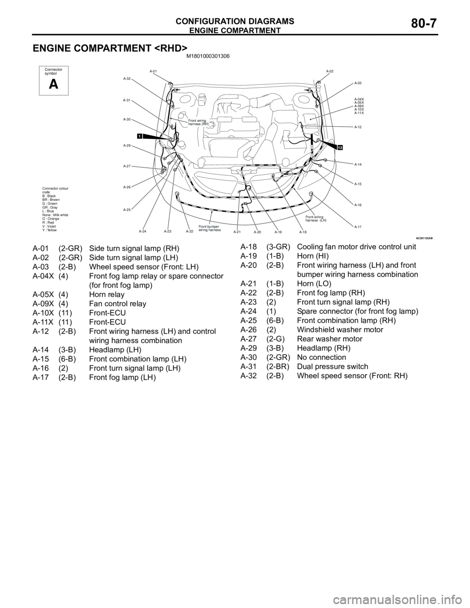
ENGINE COMPARTMENT
CONFIGURATION DIAGRAMS80-7
ENGINE COMPARTMENT
AC301125
Front wiring
harness (RH) A-01
A-32
A-31
A-29 A-30
A-27
A-26
A-25
A-23 A-24 A-22
1
Front bumper
wiring harness Connector colour
code
B : Black
BR : Brown
G : Green
GR : Gray
L : Blue
None : Milk white
O : Orange
R : Red
V : Violet
Y : Yellow
Connector
symbol
A
AB
A-02
A-03
A-04X
A-05X
A-09X
A-10X
A-11X
A-12
A-14
A-15
A-16
A-17
A-18 A-19 A-20 A-21Front wiring
harness (LH)
12
A-01 (2-GR) Side turn signal lamp (RH)
A-02 (2-GR) Side turn signal lamp (LH)
A-03 (2-B) Wheel speed sensor (Front: LH)
A-04X (4) Front fog lamp relay or spare connector
(for front fog lamp)
A-05X (4) Horn relay
A-09X (4) Fan control relay
A-10X (11) Front-ECU
A-11X (11) Front-ECU
A-12 (2-B) Front wiring harness (LH) and control
wiring harness combination
A-14 (3-B) Headlamp (LH)
A-15 (6-B) Front combination lamp (LH)
A-16 (2) Front turn signal lamp (LH)
A-17 (2-B) Front fog lamp (LH)A-18 (3-GR) Cooling fan motor drive control unit
A-19 (1-B) Horn (HI)
A-20 (2-B) Front wiring harness (LH) and front
bumper wiring harness combination
A-21 (1-B) Horn (LO)
A-22 (2-B) Front fog lamp (RH)
A-23 (2) Front turn signal lamp (RH)
A-24 (1) Spare connector (for front fog lamp)
A-25 (6-B) Front combination lamp (RH)
A-26 (2) Windshield washer motor
A-27 (2-G) Rear washer motor
A-29 (3-B) Headlamp (RH)
A-30 (2-GR) No connection
A-31 (2-BR) Dual pressure switch
A-32 (2-B) Wheel speed sensor (Front: RH)
Page 614 of 788
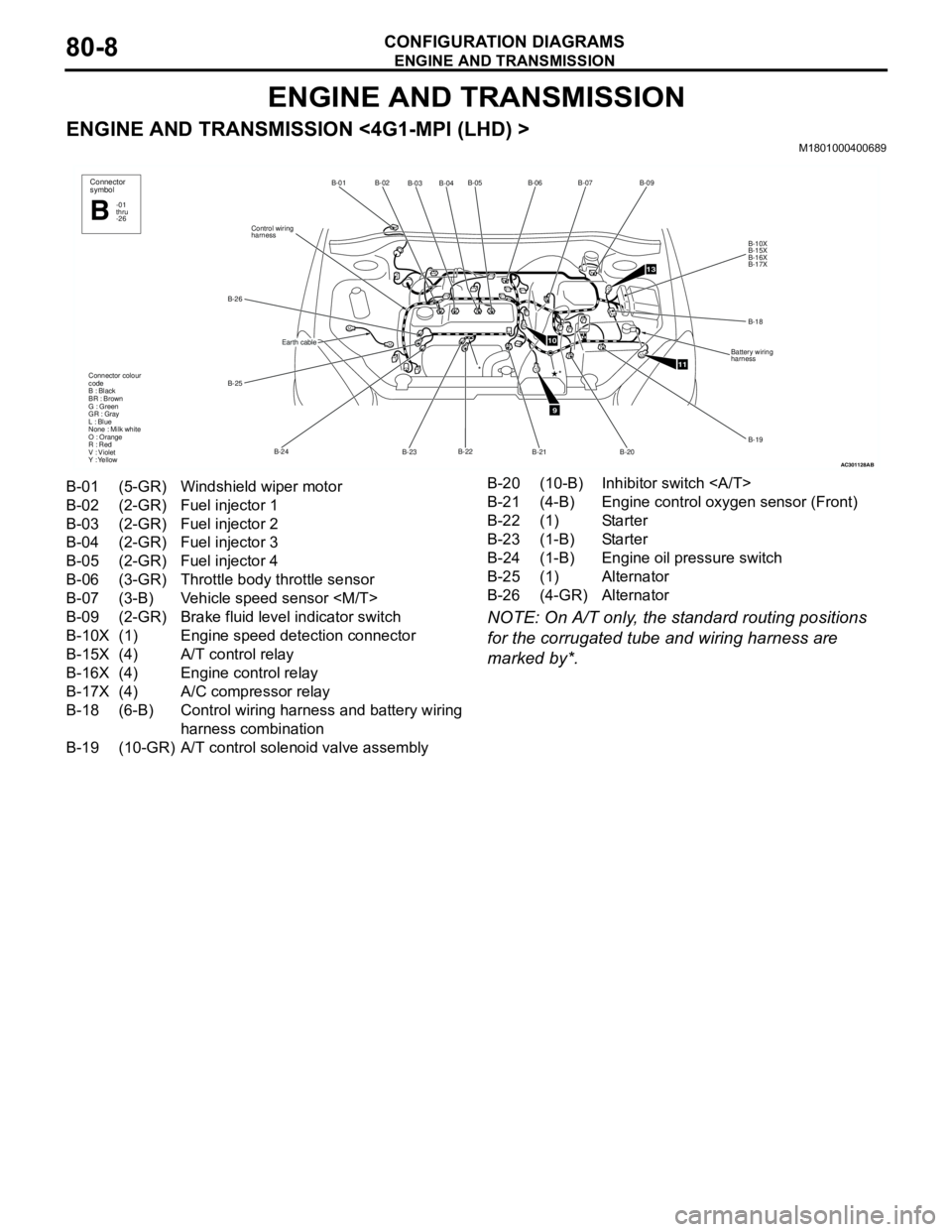
ENGINE AND TRANSMISSION
CONFIGURATION DIAGRAMS80-8
ENGINE AND TRANSMISSION
ENGINE AND TRANSMISSION <4G1-MPI (LHD) >M1801000400689
NOTE: On A/T only, the standard routing positions
for the corrugated tube and wiring harness are
marked by*.
AC301128
B-02
B-03B-04B-05
B-22
B-23 B-24 B-25 B-26Control wiring
harnessB-01
Connector colour
code
B : Black
BR : Brown
G : Green
GR : Gray
L : Blue
None : Milk white
O : Orange
R : Red
V : Violet
Y : Yellow*
Connector
symbol
-01
thru
-26B
Earth cable
AB
9
10
11
13
B-06B-07
B-09
B-10X
B-15X
B-16X
B-17X
B-18
Battery wiring
harness
B-19
B-20
B-21
*
B-01 (5-GR) Windshield wiper motor
B-02 (2-GR) Fuel injector 1
B-03 (2-GR) Fuel injector 2
B-04 (2-GR) Fuel injector 3
B-05 (2-GR) Fuel injector 4
B-06 (3-GR) Throttle body throttle sensor
B-07 (3-B) Vehicle speed sensor
B-09 (2-GR) Brake fluid level indicator switch
B-10X (1) Engine speed detection connector
B-15X (4) A/T control relay
B-16X (4) Engine control relay
B-17X (4) A/C compressor relay
B-18 (6-B) Control wiring harness and battery wiring
harness combination
B-19 (10-GR) A/T control solenoid valve assemblyB-20 (10-B) Inhibitor switch
B-21 (4-B) Engine control oxygen sensor (Front)
B-22 (1) Starter
B-23 (1-B) Starter
B-24 (1-B) Engine oil pressure switch
B-25 (1) Alternator
B-26 (4-GR) Alternator
Page 615 of 788
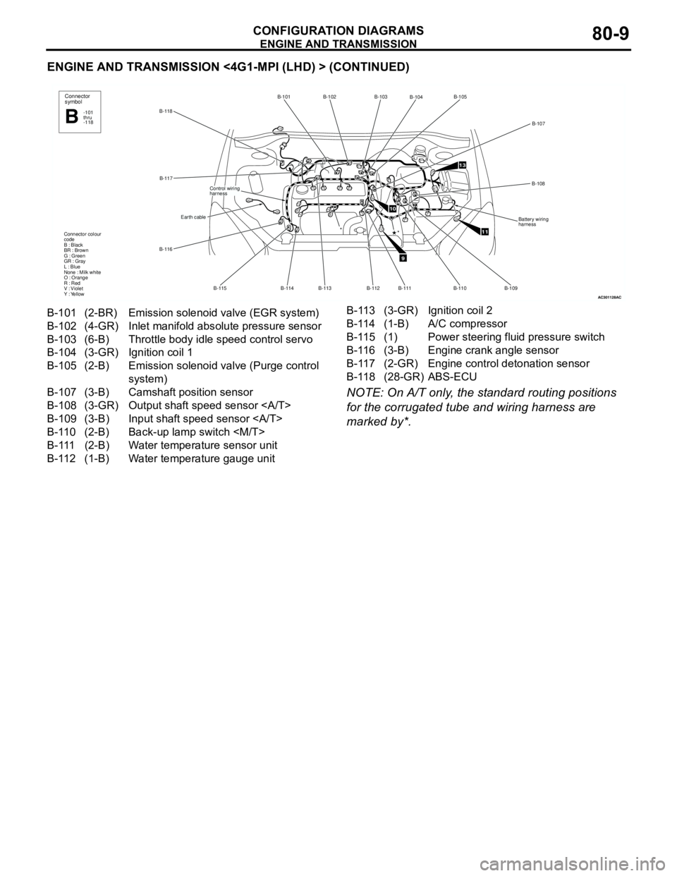
ENGINE AND TRANSMISSION
CONFIGURATION DIAGRAMS80-9
ENGINE AND TRANSMISSION <4G1-MPI (LHD) > (CONTINUED)
NOTE: On A/T only, the standard routing positions
for the corrugated tube and wiring harness are
marked by*.
AC301128
B-118B-101 B-102
B-113
B-114 B-115 B-116B-117
Earth cable
Control wiring
harness
Connector colour
code
B : Black
BR : Brown
G : Green
GR : Gray
L : Blue
None : Milk white
O : Orange
R : Red
V : Violet
Y : Yellow
Connector
symbol
-101
thru
-118B
*
AC
9
10
11
13
B-103
B-104B-105
B-107
B-108
Battery wiring
harness
B-109
B-110 B-111
*
B-112
B-101 (2-BR) Emission solenoid valve (EGR system)
B-102 (4-GR) Inlet manifold absolute pressure sensor
B-103 (6-B) Throttle body idle speed control servo
B-104 (3-GR) Ignition coil 1
B-105 (2-B) Emission solenoid valve (Purge control
system)
B-107 (3-B) Camshaft position sensor
B-108 (3-GR) Output shaft speed sensor
B-109 (3-B) Input shaft speed sensor
B-110 (2-B) Back-up lamp switch
B-111 (2-B) Water temperature sensor unit
B-112 (1-B) Water temperature gauge unitB-113 (3-GR) Ignition coil 2
B-114 (1-B) A/C compressor
B-115 (1) Power steering fluid pressure switch
B-116 (3-B) Engine crank angle sensor
B-117 (2-GR) Engine control detonation sensor
B-118 (28-GR) ABS-ECU
Page 616 of 788
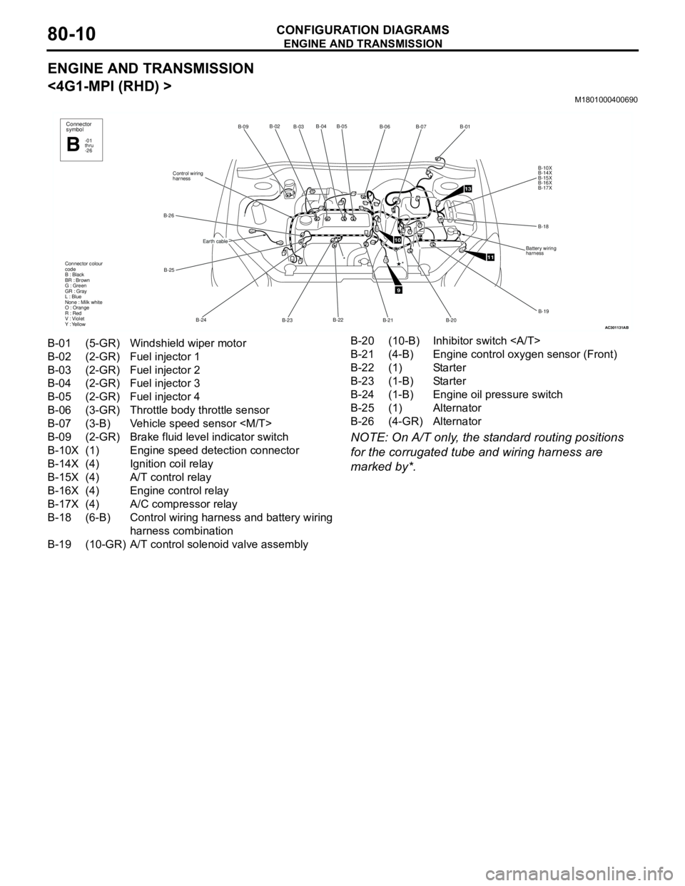
ENGINE AND TRANSMISSION
CONFIGURATION DIAGRAMS80-10
ENGINE AND TRANSMISSION
<4G1-MPI (RHD) >
M1801000400690
NOTE: On A/T only, the standard routing positions
for the corrugated tube and wiring harness are
marked by*.
AC301131
B-02
B-03B-04 B-05
B-22
B-23 B-24 B-25 B-26Control wiring
harnessB-09
Connector colour
code
B : Black
BR : Brown
G : Green
GR : Gray
L : Blue
None : Milk white
O : Orange
R : Red
V : Violet
Y : Yellow*
Connector
symbol
-01
thru
-26B
Earth cable
AB
9
10
11
13
B-06B-07
B-01
B-10X
B-14X
B-15X
B-16X
B-17X
B-18
Battery wiring
harness
B-19
B-20 B-21
*
B-01 (5-GR) Windshield wiper motor
B-02 (2-GR) Fuel injector 1
B-03 (2-GR) Fuel injector 2
B-04 (2-GR) Fuel injector 3
B-05 (2-GR) Fuel injector 4
B-06 (3-GR) Throttle body throttle sensor
B-07 (3-B) Vehicle speed sensor
B-09 (2-GR) Brake fluid level indicator switch
B-10X (1) Engine speed detection connector
B-14X (4) Ignition coil relay
B-15X (4) A/T control relay
B-16X (4) Engine control relay
B-17X (4) A/C compressor relay
B-18 (6-B) Control wiring harness and battery wiring
harness combination
B-19 (10-GR) A/T control solenoid valve assemblyB-20 (10-B) Inhibitor switch
B-21 (4-B) Engine control oxygen sensor (Front)
B-22 (1) Starter
B-23 (1-B) Starter
B-24 (1-B) Engine oil pressure switch
B-25 (1) Alternator
B-26 (4-GR) Alternator