engine overheat MITSUBISHI LANCER 2005 Workshop Manual
[x] Cancel search | Manufacturer: MITSUBISHI, Model Year: 2005, Model line: LANCER, Model: MITSUBISHI LANCER 2005Pages: 788, PDF Size: 45.98 MB
Page 30 of 788

TROUBLESHOOTING
ENGINE COOLING14-16
INSPECTION PROCEDURE 2: Cooling Fan (L.H.) and Cooling Fan (R.H.) <4G1 (Vehicles with A/C)> or
A/C Condenser Fan <4G6> do not Change Speed or Stop
COOLING FAN (L.H.) AND COOLING FAN
(R.H.) OR A/C CONDENSER FAN DRIVE
CIRCUIT
Refer to P.14-6.
CIRCUIT OPERATION
Refer to P.14-6.
TECHNICAL DESCRIPTION
•If the communication line wiring harness between
the cooling fan motor drive control unit and the
engine-ECU
is open, the cooling fan motor (L.H.) and
the cooling fan motor (R.H.) <4G1 (Vehicles with
A/C)>, or the A/C condenser fan motor <4G6>
rotate to prevent the engine from overheating.
•If the system voltage is continuously supplied to
the cooling fan motor drive control unit by a fan
motor relay malfunction and a short circuit on the
cooling fan motor drive control unit power supply
wiring harness, the cooling fan motor (L.H.) and
the cooling fan motor (R.H.) <4G1 (Vehicles with
A/C)>, or the A/C condenser fan motor <4G6>
rotate.
•The cause could also be a malfunction of the
cooling fan motor (L.H.).
•The cause could also be a malfunction of input
signal from the A/C switch, the water temperature
sensor unit and the vehicle speed sensor
or the output shaft speed sensor to the
engine-ECU
•The cause could also be a malfunction of the
cooling fan motor drive control unit or the
engine-ECU
TROUBLESHOOTING HINTS
•Malfunction of fan control relay
•Malfunction of cooling fan motor (L.H.)
•Malfunction of cooling fan motor drive control unit
•Malfunction of engine-ECU
engine-A/T-ECU
•Damaged wiring harness or connector
DIAGNOSIS
STEP 1. Check the fan control relay.
Refer to P.14-24.
Q: Is the fan control relay in good condition?
YES :
Go to Step 2 .
NO : Replace the fan control relay. Then go to
Step 8 .
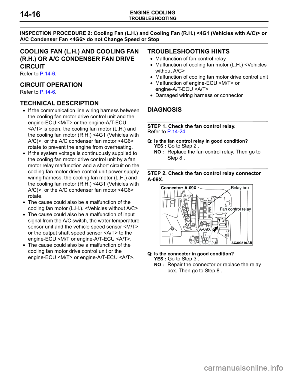
STEP 2. Check the fan control relay connector
A-09X.
Q: Is the connector in good condition?
YES :
Go to Step 3 .
NO : Repair the connector or replace the relay
box. Then go to Step 8 .
AC303510AB
Fan control relay
Relay boxConnector: A-09X
A-09X
Page 68 of 788

CHARGING SYSTEM
ENGINE ELECTRICAL16-4
2. Turn the ignition switch to the "LOCK" (OFF)
position.
3. Disconnect the negative battery cable.
4. Connect a clamp-type DC test ammeter with a
range of 0 − 120 A to the alternator "B" terminal
output wire.
NOTE: The way of disconnecting the alternator
output wire and of connecting the ammeter is
possibly not found the problem that the output
current is dropping due to the insufficient
connection between terminal "B" and the output
wire.
5. Connect a digital-type voltmeter between the
alternator "B" terminal and the battery (+)
terminal. [Connect the (+) lead of the voltmeter to
the "B" terminal and the connect the (-) lead of the
voltmeter to the battery (+) cable].
6. Reconnect the negative battery cable.
7. Connect a tachometer or the MUT-II/III (Refer to
GROUP 11A − On-vehicle Service − Idle speed
check <4G1> P.11A-11 or GROUP 11C −
On-vehicle Service − Idle speed check <4G6>
P.11C-11).
8. Leave the hood open.
9. Start the engine.
10.With the engine running at 2,500 r/min, turn the
headlamps and other lamps on and off to adjust
the alternator load so that the value displayed on
the ammeter is slightly above 30 A.Adjust the engine speed by gradually decreasing
it until the value displayed on the ammeter is 30
A. Take a reading of the value displayed on the
voltmeter at this time.
Limit: maximum 0.3 V
NOTE: When the alternator output is high and the
value displayed on the ammeter does not
decrease until 30 A, set the value to 40 A. Read
the value displayed on the voltmeter at this time.
When the value range is 40 A, the limit is
maximum 0.4 V.
11.If the value displayed on the voltmeter is above
the limit value, there is probably a malfunction in
the alternator output wire, so check the wiring
between the alternator "B" terminal and the
battery (+) terminal (including fusible link).
If a terminal is not sufficiently tight or if the
harness has become discolored due to
overheating, repair and then test again.
12.After the test, run the engine at idle.
13.Turn off all lamps and the ignition switch.
14.Remove the tachometer or the MUT-II/III.
15.Disconnect the negative battery cable.
16.Disconnect the ammeter and voltmeter.
17.Connect the negative battery cable.