group 11c MITSUBISHI LANCER 2005 Workshop Manual
[x] Cancel search | Manufacturer: MITSUBISHI, Model Year: 2005, Model line: LANCER, Model: MITSUBISHI LANCER 2005Pages: 788, PDF Size: 45.98 MB
Page 5 of 788

11-1
GROUP 11
ENGINE
CONTENTS
ENGINE MECHANICAL <4G1> . . . . . . . . . . . . . . . . . . . . . . . . .11A
ENGINE OVERHAUL <4G1> . . . . . . . . . . . . . . . . . . . . . . . . . . .11B
ENGINE MECHANICAL <4G6> . . . . . . . . . . . . . . . . . . . . . . . . .11C
ENGINE OVERHAUL <4G6> . . . . . . . . . . . . . . . . . . . . . . . . . . .11D
Page 44 of 788
WAT E R P U M P
ENGINE COOLING14-30
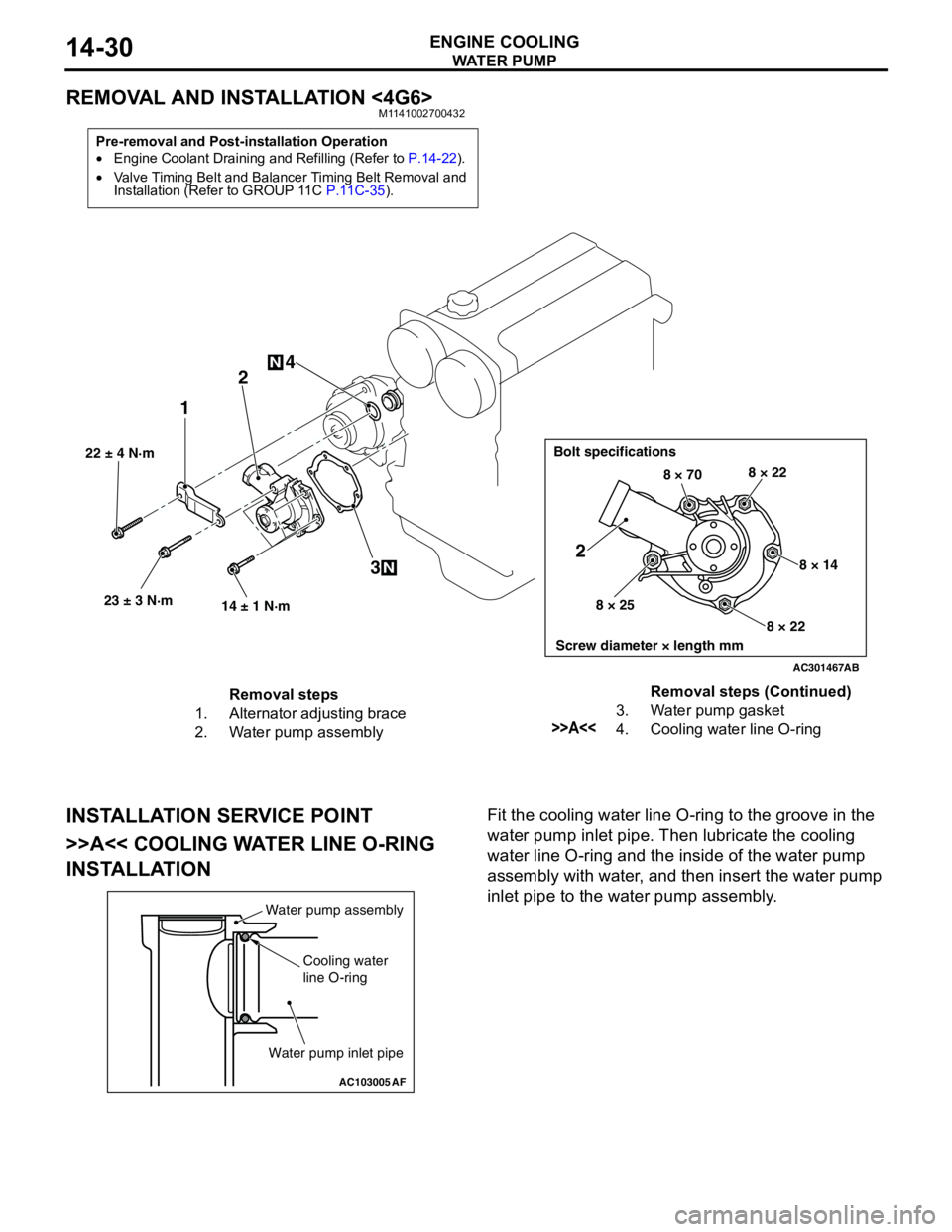
REMOVAL AND INSTALLATION <4G6>M1141002700432
INSTALLATION SERVICE POINT
>>A<< COOLING WATER LINE O-RING
INSTALLATIONFit the cooling water line O-ring to the groove in the
water pump inlet pipe. Then lubricate the cooling
water line O-ring and the inside of the water pump
assembly with water, and then insert the water pump
inlet pipe to the water pump assembly.
Pre-removal and Post-installation Operation
•Engine Coolant Draining and Refilling (Refer to P.14-22).
•Valve Timing Belt and Balancer Timing Belt Removal and
Installation (Refer to GROUP 11C P.11C-35).
AC301467
22 ± 4 N·m
23 ± 3 N·m
14 ± 1 N·m
12
3 4
N
N
Bolt specifications
Screw diameter × length mm
8 × 708 × 22
8 × 14
8 × 22 8 × 25
2
AB
Removal steps
1. Alternator adjusting brace
2. Water pump assembly3. Water pump gasket
>>A<<4. Cooling water line O-ringRemoval steps (Continued)
AC103005
Water pump assembly
Cooling water
line O-ring
Water pump inlet pipe
AF
Page 67 of 788
CHARGING SYSTEM
ENGINE ELECTRICAL16-3
SERVICE SPECIFICATIONSM1161000300258
SPECIAL TOOLM1161000600163
ON-VEHICLE SERVICE
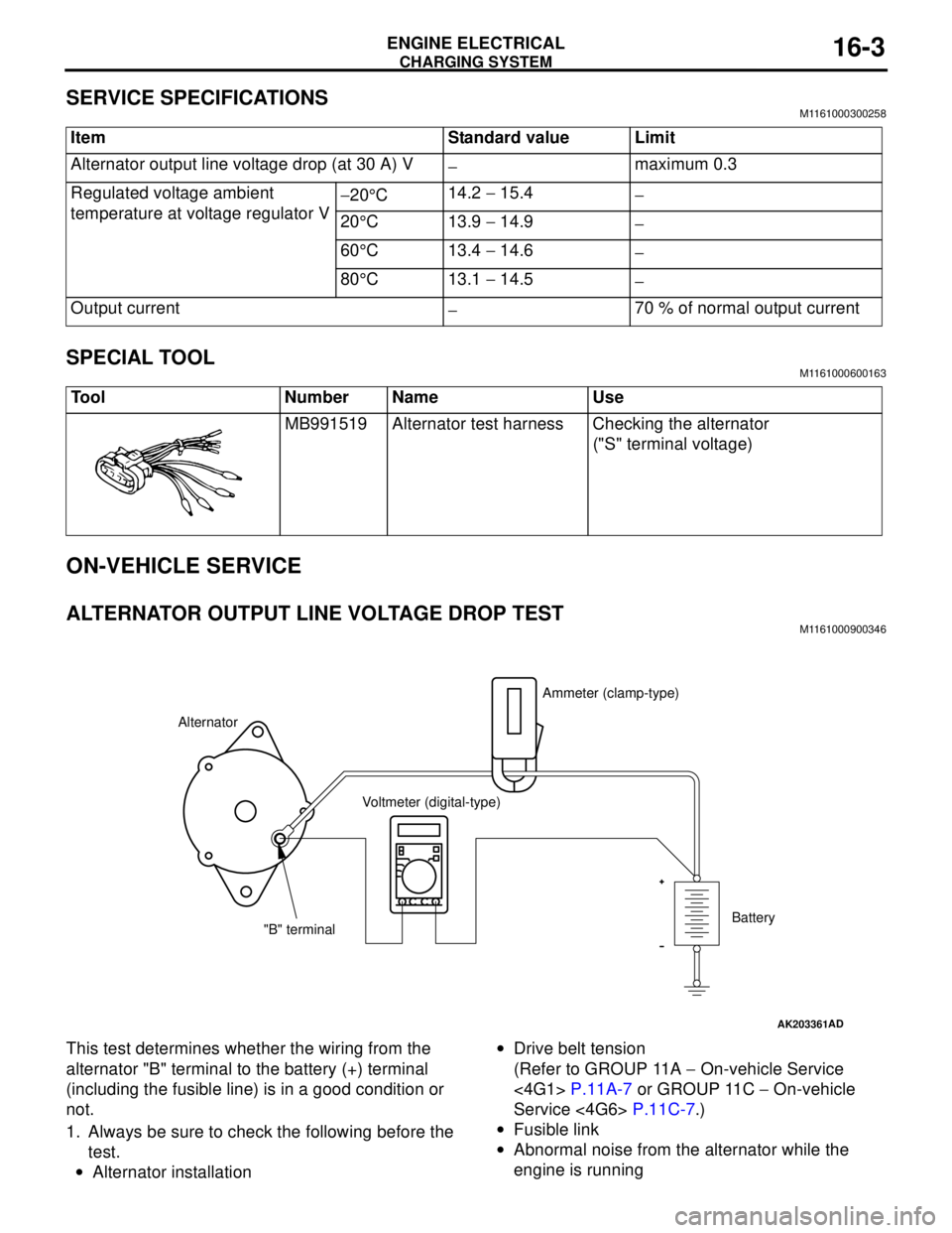
ALTERNATOR OUTPUT LINE VOLTAGE DROP TESTM1161000900346
This test determines whether the wiring from the
alternator "B" terminal to the battery (+) terminal
(including the fusible line) is in a good condition or
not.
1. Always be sure to check the following before the
test.
•Alternator installation•Drive belt tension
(Refer to GROUP 11A − On-vehicle Service
<4G1> P.11A-7 or GROUP 11C − On-vehicle
Service <4G6> P.11C-7.)
•Fusible link
•Abnormal noise from the alternator while the
engine is running Item Standard value Limit
Alternator output line voltage drop (at 30 A) V
−maximum 0.3
Regulated voltage ambient
temperature at voltage regulator V−20°C14.2 − 15.4
−
20°C 13.9 − 14.9
−
60°C 13.4 − 14.6
−
80°C 13.1 − 14.5
−
Output current
−70 % of normal output current
Tool Number Name Use
MB991519 Alternator test harness Checking the alternator
("S" terminal voltage)
AK203361AD
AlternatorAmmeter (clamp-type)
Voltmeter (digital-type)
"B" terminalBattery
Page 68 of 788

CHARGING SYSTEM
ENGINE ELECTRICAL16-4
2. Turn the ignition switch to the "LOCK" (OFF)
position.
3. Disconnect the negative battery cable.
4. Connect a clamp-type DC test ammeter with a
range of 0 − 120 A to the alternator "B" terminal
output wire.
NOTE: The way of disconnecting the alternator
output wire and of connecting the ammeter is
possibly not found the problem that the output
current is dropping due to the insufficient
connection between terminal "B" and the output
wire.
5. Connect a digital-type voltmeter between the
alternator "B" terminal and the battery (+)
terminal. [Connect the (+) lead of the voltmeter to
the "B" terminal and the connect the (-) lead of the
voltmeter to the battery (+) cable].
6. Reconnect the negative battery cable.
7. Connect a tachometer or the MUT-II/III (Refer to
GROUP 11A − On-vehicle Service − Idle speed
check <4G1> P.11A-11 or GROUP 11C −
On-vehicle Service − Idle speed check <4G6>
P.11C-11).
8. Leave the hood open.
9. Start the engine.
10.With the engine running at 2,500 r/min, turn the
headlamps and other lamps on and off to adjust
the alternator load so that the value displayed on
the ammeter is slightly above 30 A.Adjust the engine speed by gradually decreasing
it until the value displayed on the ammeter is 30
A. Take a reading of the value displayed on the
voltmeter at this time.
Limit: maximum 0.3 V
NOTE: When the alternator output is high and the
value displayed on the ammeter does not
decrease until 30 A, set the value to 40 A. Read
the value displayed on the voltmeter at this time.
When the value range is 40 A, the limit is
maximum 0.4 V.
11.If the value displayed on the voltmeter is above
the limit value, there is probably a malfunction in
the alternator output wire, so check the wiring
between the alternator "B" terminal and the
battery (+) terminal (including fusible link).
If a terminal is not sufficiently tight or if the
harness has become discolored due to
overheating, repair and then test again.
12.After the test, run the engine at idle.
13.Turn off all lamps and the ignition switch.
14.Remove the tachometer or the MUT-II/III.
15.Disconnect the negative battery cable.
16.Disconnect the ammeter and voltmeter.
17.Connect the negative battery cable.
Page 69 of 788
CHARGING SYSTEM
ENGINE ELECTRICAL16-5
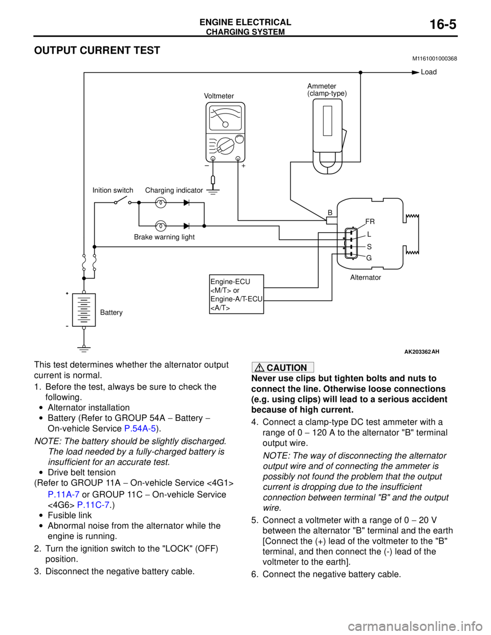
OUTPUT CURRENT TESTM1161001000368
This test determines whether the alternator output
current is normal.
1. Before the test, always be sure to check the
following.
•Alternator installation
•Battery (Refer to GROUP 54A − Battery −
On-vehicle Service P.54A-5).
NOTE: The battery should be slightly discharged.
The load needed by a fully-charged battery is
insufficient for an accurate test.
•Drive belt tension
(Refer to GROUP 11A − On-vehicle Service <4G1>
P.11A-7 or GROUP 11C − On-vehicle Service
<4G6> P.11C-7.)
•Fusible link
•Abnormal noise from the alternator while the
engine is running.
2. Turn the ignition switch to the "LOCK" (OFF)
position.
3. Disconnect the negative battery cable.CAUTION
Never use clips but tighten bolts and nuts to
connect the line. Otherwise loose connections
(e.g. using clips) will lead to a serious accident
because of high current.
4. Connect a clamp-type DC test ammeter with a
range of 0 − 120 A to the alternator "B" terminal
output wire.
NOTE: The way of disconnecting the alternator
output wire and of connecting the ammeter is
possibly not found the problem that the output
current is dropping due to the insufficient
connection between terminal "B" and the output
wire.
5. Connect a voltmeter with a range of 0 − 20 V
between the alternator "B" terminal and the earth
[Connect the (+) lead of the voltmeter to the "B"
terminal, and then connect the (-) lead of the
voltmeter to the earth].
6. Connect the negative battery cable.
AK203362
Alternator Ammeter
(clamp-type)
Voltmeter
Battery Inition switch
Engine-ECU
Engine-A/T-ECU
Load
B
FR
L
S
G +
AH
–
Charging indicator
Brake warning light
Page 70 of 788

CHARGING SYSTEM
ENGINE ELECTRICAL16-6
7. Connect a tachometer or the MUT-II/III (Refer to
GROUP 11A − On-vehicle Service − Idle speed
check <4G1> P.11A-11 or GROUP 11C −
On-vehicle Service − Idle speed check <4G6>
P.11C-11).
8. Leave the hood open.
9. Check that the reading on the voltmeter is equal
to the battery voltage.
NOTE: If the voltage is 0 V, the cause is probably
an open circuit in the wire or fusible link between
the alternator "B" terminal and the battery (+)
terminal.
10.Turn the light switch on to turn on headlamps and
then start the engine.
11.Immediately after setting the headlamps to high
beam and turning the heater blower switch to the
high revolution position, increase the engine
speed to 2,500 r/min and read the maximum
current output value displayed on the ammeter.
Limit: 70 % of normal current outputNOTE: .
•For the nominal current output, refer to the
Alternator Specifications.
•Because the current from the battery will soon
drop after the engine is started, the above step
should be carried out as quickly as possible in
order to obtain the maximum current output
value.
•The current output value will depend on the
electrical load and the temperature of the
alternator body.
•If the electrical load is small while testing, the
specified level of current may not be output
even though the alternator is normal. In such
cases, increase the electrical load by leaving
the headlamps turned on for some time to
discharge the battery or by using the lighting
system in another vehicle, and then test again.
•The specified level of current also may not be
output if the temperature of the alternator body
or the ambient temperature is too high. In such
cases, cool the alternator and then test again.
12.The reading on the ammeter should be above the
limit value. If the reading is below the limit value
and the alternator output wire is normal, remove
the alternator from the engine and check the
alternator.
13.Run the engine at idle after the test.
14.Turn the ignition switch to the "LOCK" (OFF)
position.
15.Remove the tachometer or the MUT-II/III.
16.Disconnect the negative battery cable.
17.Disconnect the ammeter and voltmeter.
18.Connect the negative battery cable.
Page 71 of 788
CHARGING SYSTEM
ENGINE ELECTRICAL16-7
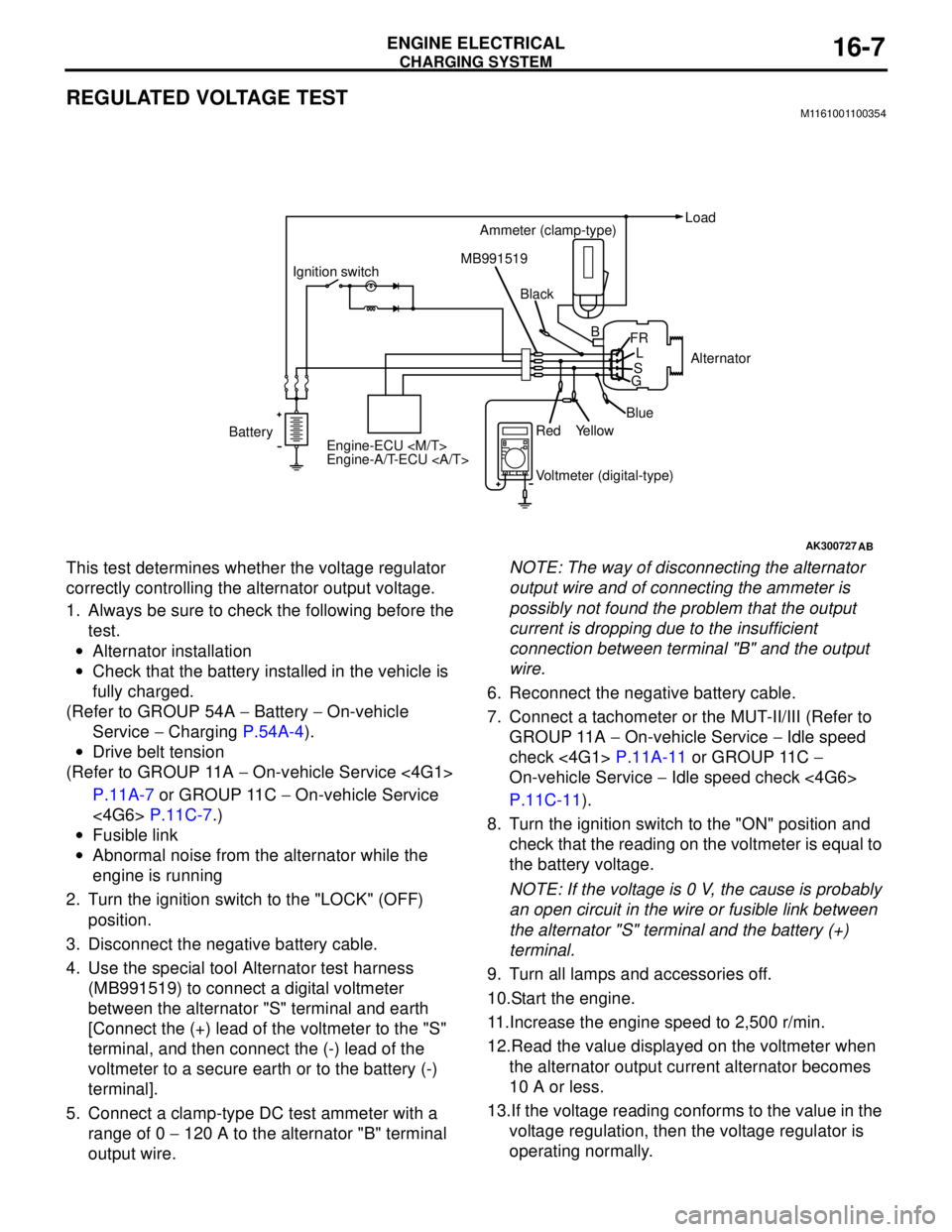
REGULATED VOLTAGE TESTM1161001100354
This test determines whether the voltage regulator
correctly controlling the alternator output voltage.
1. Always be sure to check the following before the
test.
•Alternator installation
•Check that the battery installed in the vehicle is
fully charged.
(Refer to GROUP 54A − Battery − On-vehicle
Service − Charging P.54A-4).
•Drive belt tension
(Refer to GROUP 11A − On-vehicle Service <4G1>
P.11A-7 or GROUP 11C − On-vehicle Service
<4G6> P.11C-7.)
•Fusible link
•Abnormal noise from the alternator while the
engine is running
2. Turn the ignition switch to the "LOCK" (OFF)
position.
3. Disconnect the negative battery cable.
4. Use the special tool Alternator test harness
(MB991519) to connect a digital voltmeter
between the alternator "S" terminal and earth
[Connect the (+) lead of the voltmeter to the "S"
terminal, and then connect the (-) lead of the
voltmeter to a secure earth or to the battery (-)
terminal].
5. Connect a clamp-type DC test ammeter with a
range of 0 − 120 A to the alternator "B" terminal
output wire.NOTE: The way of disconnecting the alternator
output wire and of connecting the ammeter is
possibly not found the problem that the output
current is dropping due to the insufficient
connection between terminal "B" and the output
wire.
6. Reconnect the negative battery cable.
7. Connect a tachometer or the MUT-II/III (Refer to
GROUP 11A − On-vehicle Service − Idle speed
check <4G1> P.11A-11 or GROUP 11C −
On-vehicle Service − Idle speed check <4G6>
P.11C-11).
8. Turn the ignition switch to the "ON" position and
check that the reading on the voltmeter is equal to
the battery voltage.
NOTE: If the voltage is 0 V, the cause is probably
an open circuit in the wire or fusible link between
the alternator "S" terminal and the battery (+)
terminal.
9. Turn all lamps and accessories off.
10.Start the engine.
11.Increase the engine speed to 2,500 r/min.
12.Read the value displayed on the voltmeter when
the alternator output current alternator becomes
10 A or less.
13.If the voltage reading conforms to the value in the
voltage regulation, then the voltage regulator is
operating normally.
AK300727AB
BatteryIgnition switch
Engine-ECU
Engine-A/T-ECU Ammeter (clamp-type)Load
Black MB991519
Voltmeter (digital-type) Red
YellowBlueAlternator B
FR
L
S
G
Page 77 of 788
CHARGING SYSTEM
ENGINE ELECTRICAL16-13
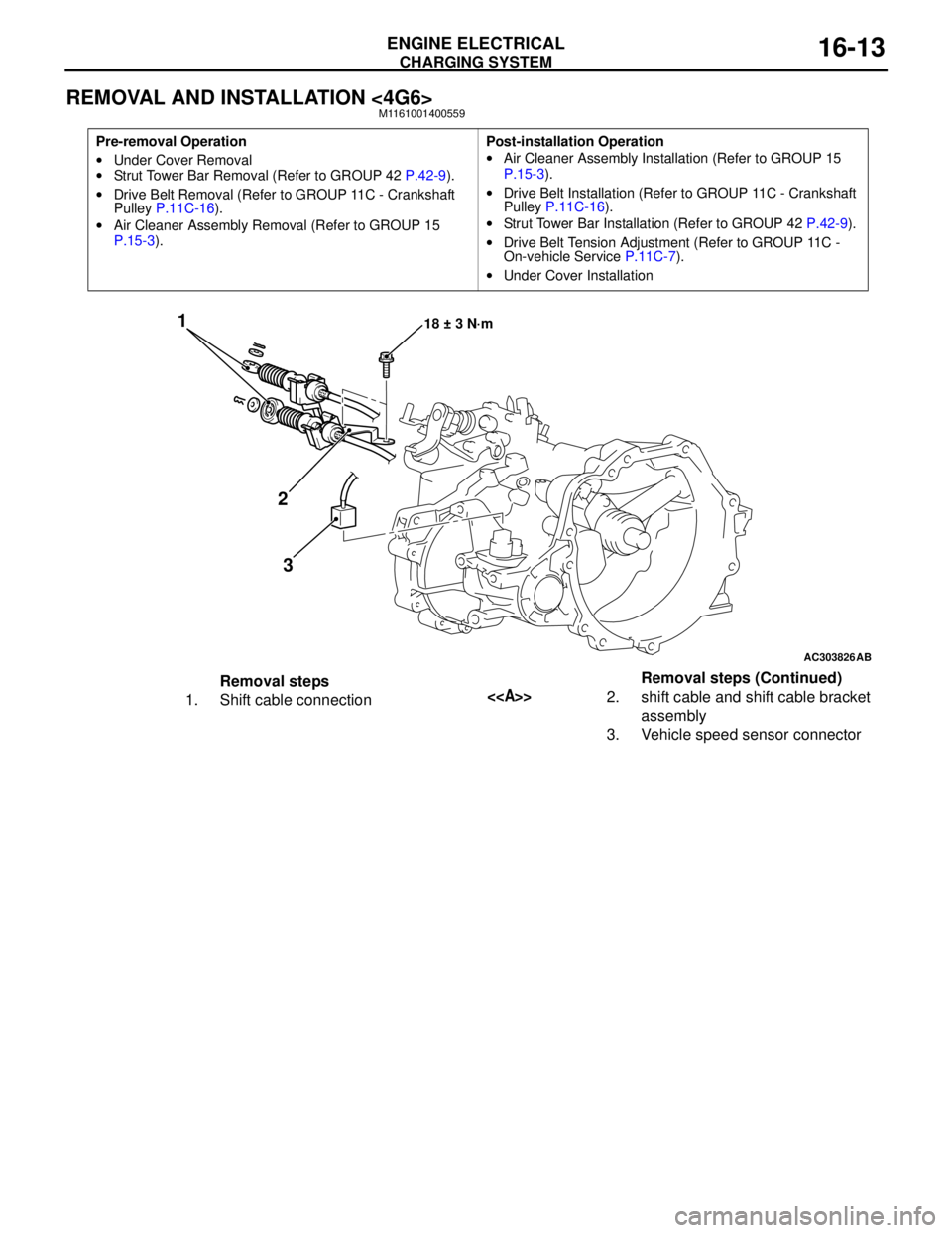
REMOVAL AND INSTALLATION <4G6>M1161001400559
Pre-removal Operation
•Under Cover Removal
•Strut Tower Bar Removal (Refer to GROUP 42 P.42-9).
•Drive Belt Removal (Refer to GROUP 11C - Crankshaft
Pulley P.11C-16).
•Air Cleaner Assembly Removal (Refer to GROUP 15
P.15-3).Post-installation Operation
•Air Cleaner Assembly Installation (Refer to GROUP 15
P.15-3).
•Drive Belt Installation (Refer to GROUP 11C - Crankshaft
Pulley P.11C-16).
•Strut Tower Bar Installation (Refer to GROUP 42 P.42-9).
•Drive Belt Tension Adjustment (Refer to GROUP 11C -
On-vehicle Service P.11C-7).
•Under Cover Installation
AC303826
1
2
318 ± 3 N·m
AB
Removal steps
1. Shift cable connection<>2. shift cable and shift cable bracket
assembly
3. Vehicle speed sensor connectorRemoval steps (Continued)
Page 106 of 788
IGNITION SYSTEM
ENGINE ELECTRICAL16-42
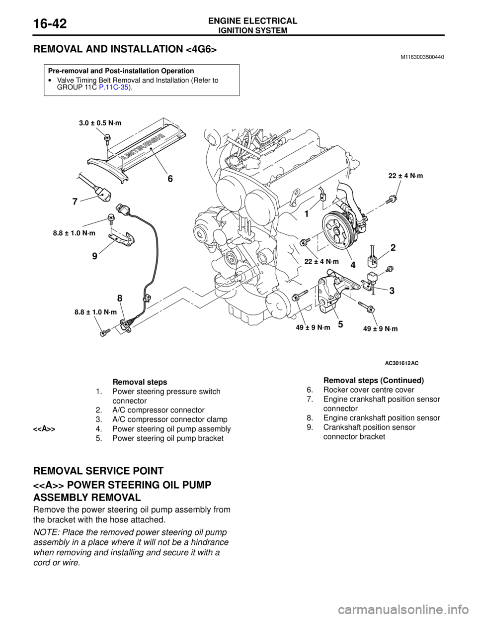
REMOVAL AND INSTALLATION <4G6>M1163003500440
REMOVAL SERVICE POINT
<> POWER STEERING OIL PUMP
ASSEMBLY REMOVAL
Remove the power steering oil pump assembly from
the bracket with the hose attached.
NOTE: Place the removed power steering oil pump
assembly in a place where it will not be a hindrance
when removing and installing and secure it with a
cord or wire.
Pre-removal and Post-installation Operation
•Valve Timing Belt Removal and Installation (Refer to
GROUP 11C P.11C-35).
AC301612
8.8 ± 1.0 N·m
8
8.8 ± 1.0 N·m
9
1
22 ± 4 N·m
4
2
3
49 ± 9 N·m49 ± 9 N·m5
22 ± 4 N·m
3.0 ± 0.5 N·m
6
7
AC
Removal steps
1. Power steering pressure switch
connector
2. A/C compressor connector
3. A/C compressor connector clamp
<>4. Power steering oil pump assembly
5. Power steering oil pump bracket6. Rocker cover centre cover
7. Engine crankshaft position sensor
connector
8. Engine crankshaft position sensor
9. Crankshaft position sensor
connector bracket Removal steps (Continued)
Page 247 of 788
ON-VEHICLE SERVICE
POWER STEERING37-13
STEERING WHEEL RETURN TO CENTRE
CHECK
M1372001800317
Conduct a road test:
1. Make both gradual and sudden turns and check
the steering wheel return.
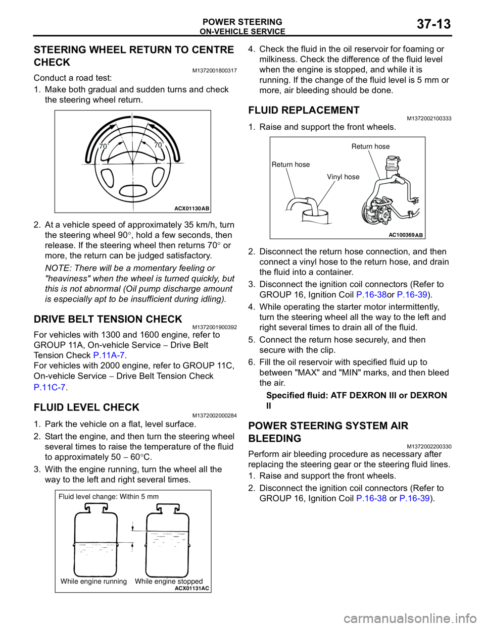
2. At a vehicle speed of approximately 35 km/h, turn
the steering wheel 90°, hold a few seconds, then
release. If the steering wheel then returns 70° or
more, the return can be judged satisfactory.
NOTE: There will be a momentary feeling or
"heaviness" when the wheel is turned quickly, but
this is not abnormal (Oil pump discharge amount
is especially apt to be insufficient during idling).
DRIVE BELT TENSION CHECKM1372001900392
For vehicles with 1300 and 1600 engine, refer to
GROUP 11A, On-vehicle Service − Drive Belt
Tension Check P.11A-7.
For vehicles with 2000 engine, refer to GROUP 11C,
On-vehicle Service − Drive Belt Tension Check
P.11C-7.
FLUID LEVEL CHECKM1372002000284
1. Park the vehicle on a flat, level surface.
2. Start the engine, and then turn the steering wheel
several times to raise the temperature of the fluid
to approximately 50 − 60°C.
3. With the engine running, turn the wheel all the
way to the left and right several times.4. Check the fluid in the oil reservoir for foaming or
milkiness. Check the difference of the fluid level
when the engine is stopped, and while it is
running. If the change of the fluid level is 5 mm or
more, air bleeding should be done.
FLUID REPLACEMENTM1372002100333
1. Raise and support the front wheels.
2. Disconnect the return hose connection, and then
connect a vinyl hose to the return hose, and drain
the fluid into a container.
3. Disconnect the ignition coil connectors (Refer to
GROUP 16, Ignition Coil P.16-38or P.16-39).
4. While operating the starter motor intermittently,
turn the steering wheel all the way to the left and
right several times to drain all of the fluid.
5. Connect the return hose securely, and then
secure with the clip.
6. Fill the oil reservoir with specified fluid up to
between "MAX" and "MIN" marks, and then bleed
the air.
Specified fluid: ATF DEXRON III or DEXRON
II
POWER STEERING SYSTEM AIR
BLEEDING
M1372002200330
Perform air bleeding procedure as necessary after
replacing the steering gear or the steering fluid lines.
1. Raise and support the front wheels.
2. Disconnect the ignition coil connectors (Refer to
GROUP 16, Ignition Coil P.16-38 or P.16-39).
ACX01130
AB
70˚70˚
ACX01131While engine running While engine stoppedAC
Fluid level change: Within 5 mm
AC100369AB
Return hoseReturn hose
Vinyl hose