rear MITSUBISHI LANCER 2005 Workshop Manual
[x] Cancel search | Manufacturer: MITSUBISHI, Model Year: 2005, Model line: LANCER, Model: MITSUBISHI LANCER 2005Pages: 788, PDF Size: 45.98 MB
Page 1 of 788
GROUP INDEX
00General . . . . . . . . . . . . . . . . . . . . . . . .
11Engine. . . . . . . . . . . . . . . . . . . . . . . . .
12Engine Lubrication . . . . . . . . . . . . . .
13Fuel . . . . . . . . . . . . . . . . . . . . . . . . . . .
14Engine Cooling . . . . . . . . . . . . . . . . .
15Intake and Exhaust . . . . . . . . . . . . . .
16Engine Electrical . . . . . . . . . . . . . . . .
17Engine and Emission Control . . . . .
21Clutch . . . . . . . . . . . . . . . . . . . . . . . . .
22Manual Transmission . . . . . . . . . . . .
23Automatic Transmission. . . . . . . . . .
26Front Axle . . . . . . . . . . . . . . . . . . . . . .
27Rear Axle . . . . . . . . . . . . . . . . . . . . . .
31Wheel and Tyre . . . . . . . . . . . . . . . . .
32Power Plant Mount . . . . . . . . . . . . . .
33Front Suspension . . . . . . . . . . . . . . .
34Rear Suspension . . . . . . . . . . . . . . . .
35Service Brakes . . . . . . . . . . . . . . . . . .
36Parking Brakes . . . . . . . . . . . . . . . . .
37Power Steering . . . . . . . . . . . . . . . . .
42Body . . . . . . . . . . . . . . . . . . . . . . . . . .
51Exterior . . . . . . . . . . . . . . . . . . . . . . . .
52 . . . . . . . . . .
54Chassis Electrical . . . . . . . . . . . . . . .
55 . . . . . . .
70Component Locations. . . . . . . . . . . .
80Configration Diagrams . . . . . . . . . . .
90Circuit Diagrams . . . . . . . . . . . . . . . .
LANCER /
LANCER WAGON
WORKSHOP MANUAL
FOREWORD
This Workshop manual contains procedures for
service mechanics, including removal, disassembly,
inspection, adjustment, reassembly and installation.
Use the following manuals in combination with this
manual as required.
TECHNICAL INFORMATION MANUAL
PYME0302
PYME0302-A
WORKSHOP MANUAL
CHASSIS GROUP PWME0302
BODY REPAIR MANUAL
PBME0302
PBME0302-A
PARTS CATALOGUE
B606K005A_
All information, illustrations and product descriptions
contained in this manual are current as at the time of
publication. We, however, reserve the right to make
changes at any time without prior notice or obligation.
Mitsubishi Motors Corporation May 2004
Heater, Air Conditioner and
Ventilation Interior and Supplemental
Restraint System (SRS)
Page 63 of 788
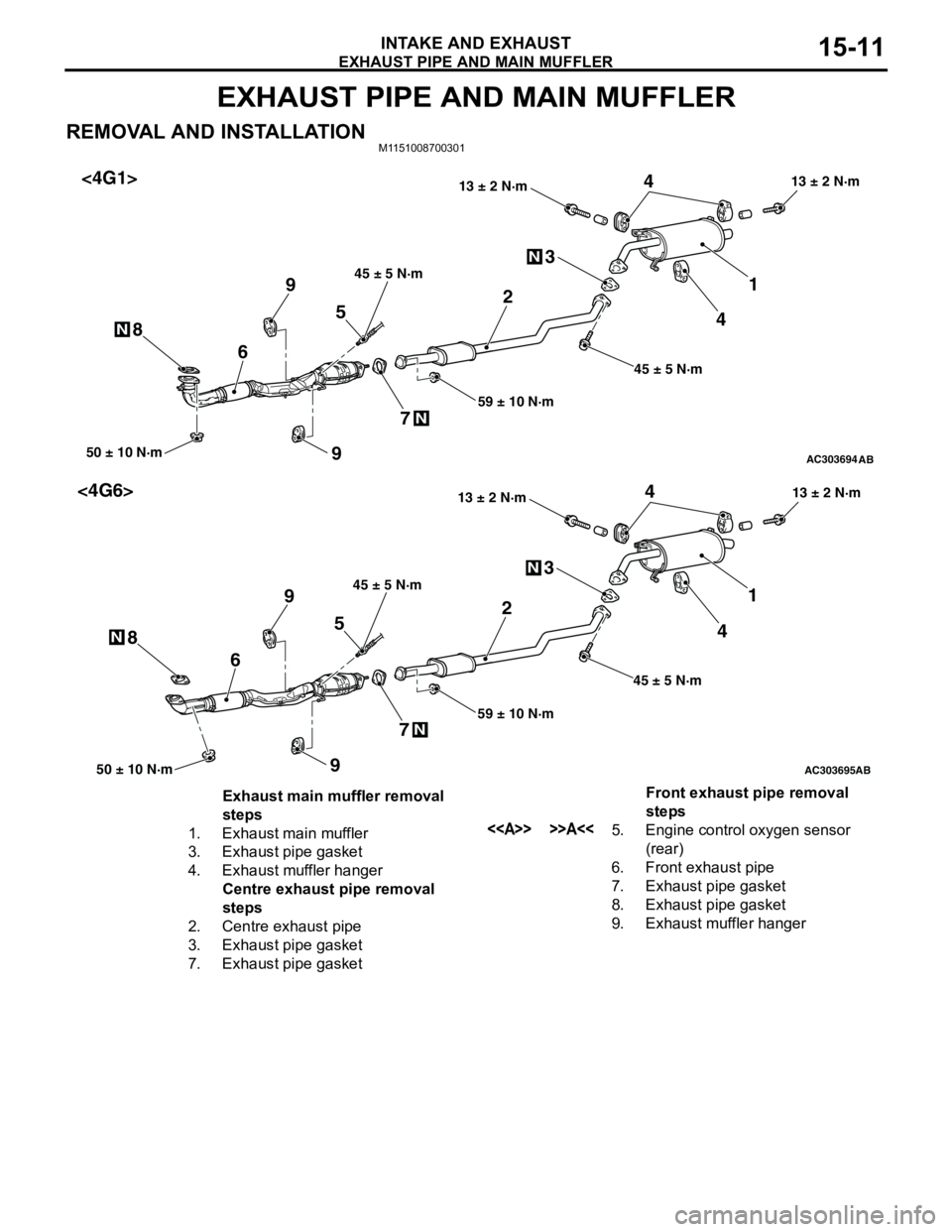
EXHAUST PIPE AND MAIN MUFFLER
INTAKE AND EXHAUST15-11
EXHAUST PIPE AND MAIN MUFFLER
REMOVAL AND INSTALLATIONM1151008700301
AC303694AB
1 3
50 ± 10 N·m
2
6
N
N
45
74
N89
59 ± 10 N·m 45 ± 5 N·m13 ± 2 N·m
45 ± 5 N·m
13 ± 2 N·m
9
<4G1>
AC303695AB
1 3
50 ± 10 N·m
2
6
N
N
45
74
N89
59 ± 10 N·m 45 ± 5 N·m13 ± 2 N·m
45 ± 5 N·m
13 ± 2 N·m
9
<4G6>
Exhaust main muffler removal
steps
1. Exhaust main muffler
3. Exhaust pipe gasket
4. Exhaust muffler hanger
Centre exhaust pipe removal
steps
2. Centre exhaust pipe
3. Exhaust pipe gasket
7. Exhaust pipe gasketFront exhaust pipe removal
steps
<> >>A<<5. Engine control oxygen sensor
(rear)
6. Front exhaust pipe
7. Exhaust pipe gasket
8. Exhaust pipe gasket
9. Exhaust muffler hanger
Page 64 of 788
EXHAUST PIPE AND MAIN MUFFLER
INTAKE AND EXHAUST15-12
REMOVAL SERVICE POINT
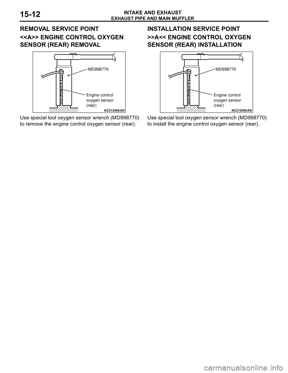
<> ENGINE CONTROL OXYGEN
SENSOR (REAR) REMOVAL
Use special tool oxygen sensor wrench (MD998770)
to remove the engine control oxygen sensor (rear).
INSTALLATION SERVICE POINT
>>A<< ENGINE CONTROL OXYGEN
SENSOR (REAR) INSTALLATION
Use special tool oxygen sensor wrench (MD998770)
to install the engine control oxygen sensor (rear).
AC212566AD
MD998770
Engine control
oxygen sensor
(rear)
AC212566AD
MD998770
Engine control
oxygen sensor
(rear)
Page 79 of 788
CHARGING SYSTEM
ENGINE ELECTRICAL16-15
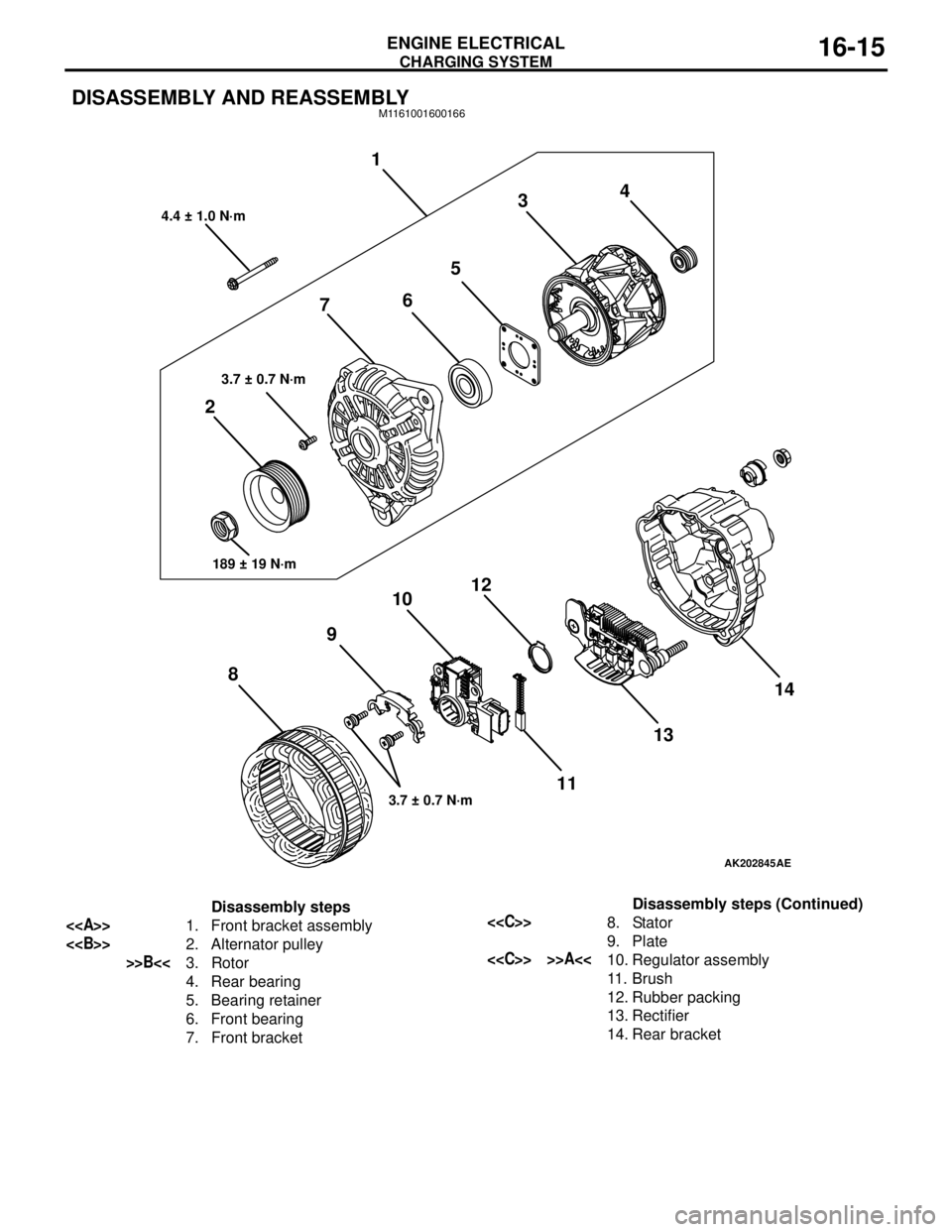
DISASSEMBLY AND REASSEMBLYM1161001600166
AK202845
1
234
5
6
7
8910
11 12
1314
AE
4.4 ± 1.0 N·m
3.7 ± 0.7 N·m
189 ± 19 N·m
3.7 ± 0.7 N·m
Disassembly steps
<>1. Front bracket assembly
<>2. Alternator pulley
>>B<<3. Rotor
4. Rear bearing
5. Bearing retainer
6. Front bearing
7. Front bracket
<
9. Plate
<
11 . B r u s h
12. Rubber packing
13. Rectifier
14. Rear bracketDisassembly steps (Continued)
Page 80 of 788
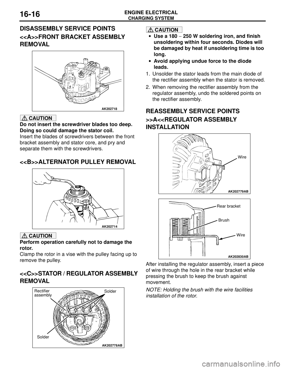
Page 90 of 788
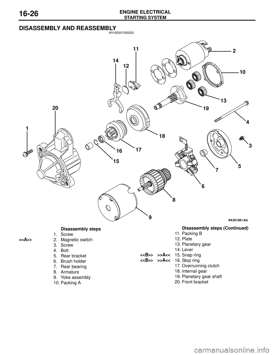
STARTING SYSTEM
ENGINE ELECTRICAL16-26
DISASSEMBLY AND REASSEMBLYM1162001200202
AK201881
14
1211
20
1
15161718191310 2
4
3
5
7
6
8
9
AG
Disassembly steps
1. Screw
<>2. Magnetic switch
3. Screw
4. Bolt
5. Rear bracket
6. Brush holder
7. Rear bearing
8. Armature
9. Yoke assembly
10. Packing A11. Packing B
12. Plate
13. Planetary gear
14. Lever
<> >>A<<15. Snap ring
<> >>A<<16. Stop ring
17. Overrunning clutch
18. Internal gear
19. Planetary gear shaft
20. Front bracketDisassembly steps (Continued)
Page 114 of 788
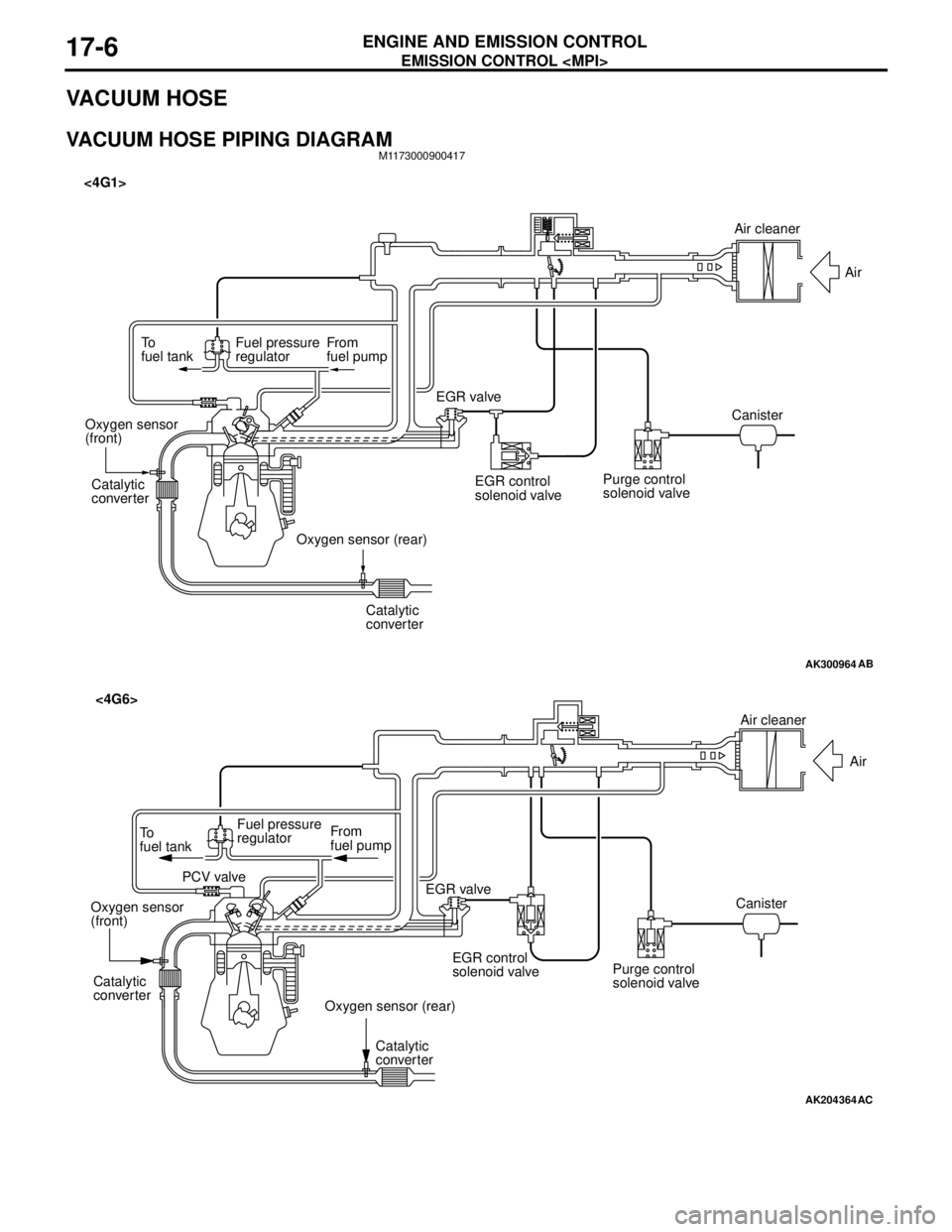
EMISSION CONTROL
ENGINE AND EMISSION CONTROL17-6
VACUUM HOSE
VACUUM HOSE PIPING DIAGRAMM1173000900417
AK300964
To
fuel tankFuel pressure
regulatorFrom
fuel pump
Catalytic
converter
Catalytic
converter Oxygen sensor
(front)
Oxygen sensor (rear)EGR valve <4G1>
EGR control
solenoid valvePurge control
solenoid valveCanisterAir
AB
Air cleaner
AK204364
AC
Air cleaner
Air
Canister
Purge control
solenoid valve EGR control
solenoid valve EGR valve From
fuel pump To
fuel tankFuel pressure
regulator
PCV valve
Oxygen sensor
(front)
Oxygen sensor (rear) Catalytic
converter
Catalytic
converter
<4G6>
Page 137 of 788
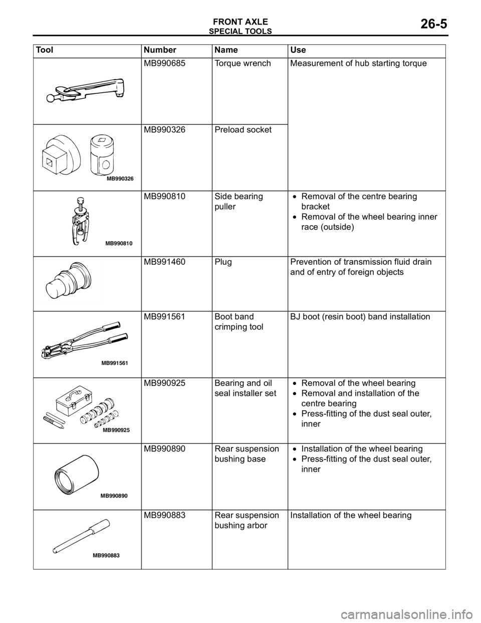
SPECIAL TOOLS
FRONT AXLE26-5
MB990685 Torque wrench Measurement of hub starting torque
MB990326 Preload socket
MB990810 Side bearing
puller•Removal of the centre bearing
bracket
•Removal of the wheel bearing inner
race (outside)
MB991460 Plug Prevention of transmission fluid drain
and of entry of foreign objects
MB991561 Boot band
crimping toolBJ boot (resin boot) band installation
MB990925 Bearing and oil
seal installer set•Removal of the wheel bearing
•Removal and installation of the
centre bearing
•Press-fitting of the dust seal outer,
inner
MB990890 Rear suspension
bushing base•Installation of the wheel bearing
•Press-fitting of the dust seal outer,
inner
MB990883 Rear suspension
bushing arborInstallation of the wheel bearing Tool Number Name Use
MB990326
MB990810
MB991561
MB990925
MB990890
MB990883
Page 145 of 788
FRONT AXLE HUB ASSEMBLY
FRONT AXLE26-13
REASSEMBLY SERVICE POINTS
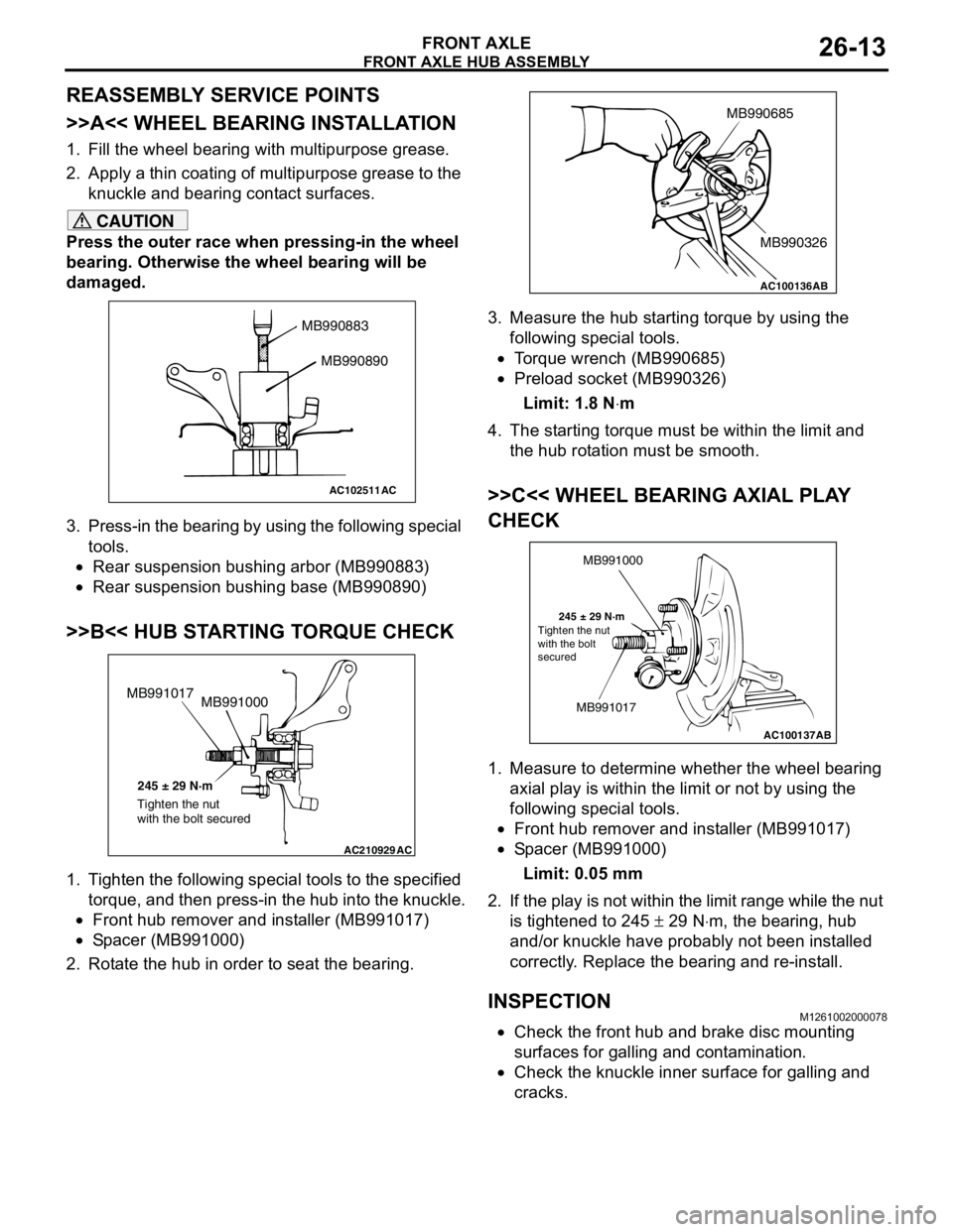
>>A<< WHEEL BEARING INSTALLATION
1. Fill the wheel bearing with multipurpose grease.
2. Apply a thin coating of multipurpose grease to the
knuckle and bearing contact surfaces.
CAUTION
Press the outer race when pressing-in the wheel
bearing. Otherwise the wheel bearing will be
damaged.
3. Press-in the bearing by using the following special
tools.
•Rear suspension bushing arbor (MB990883)
•Rear suspension bushing base (MB990890)
>>B<< HUB STARTING TORQUE CHECK
1. Tighten the following special tools to the specified
torque, and then press-in the hub into the knuckle.
•Front hub remover and installer (MB991017)
•Spacer (MB991000)
2. Rotate the hub in order to seat the bearing.3. Measure the hub starting torque by using the
following special tools.
•Torque wrench (MB990685)
•Preload socket (MB990326)
Limit: 1.8 N⋅m
4. The starting torque must be within the limit and
the hub rotation must be smooth.
>>C<< WHEEL BEARING AXIAL PLAY
CHECK
1. Measure to determine whether the wheel bearing
axial play is within the limit or not by using the
following special tools.
•Front hub remover and installer (MB991017)
•Spacer (MB991000)
Limit: 0.05 mm
2. If the play is not within the limit range while the nut
is tightened to 245 ± 29 N⋅m, the bearing, hub
and/or knuckle have probably not been installed
correctly. Replace the bearing and re-install.
INSPECTIONM1261002000078
•Check the front hub and brake disc mounting
surfaces for galling and contamination.
•Check the knuckle inner surface for galling and
cracks.
AC102511
MB990883
MB990890
AC
AC210929AC
MB991000 MB991017
245 ± 29 N·m
Tighten the nut
with the bolt secured
AC100136
MB990685
MB990326
AB
AC100137
MB991000
MB991017
245 ± 29 N·m
AB Tighten the nut
with the bolt
secured
Page 157 of 788
27-1
GROUP 27
REAR AXLE
CONTENTS
GENERAL INFORMATION . . . . . . . .27-2
SERVICE SPECIFICATIONS . . . . . . .27-2
SEALANT . . . . . . . . . . . . . . . . . . . . . .27-2
SPECIAL TOOLS . . . . . . . . . . . . . . . .27-3ON-VEHICLE SERVICE . . . . . . . . . . .27-4
WHEEL BEARING AXIAL PLAY CHECK . . 27-4
REAR HUB ROTARY-SLIDING
RESISTANCE CHECK . . . . . . . . . . . . . . . . 27-4
HUB BOLT REPLACEMENT . . . . . . . . . . . . 27-4
REAR AXLE HUB ASSEMBLY . . . . .27-5
REMOVAL AND INSTALLATION . . . . . . . . 27-5
INSPECTION . . . . . . . . . . . . . . . . . . . . . . . . 27-6