tow bar MITSUBISHI LANCER 2005 Workshop Manual
[x] Cancel search | Manufacturer: MITSUBISHI, Model Year: 2005, Model line: LANCER, Model: MITSUBISHI LANCER 2005Pages: 788, PDF Size: 45.98 MB
Page 57 of 788
INLET MANIFOLD
INTAKE AND EXHAUST15-5
INLET MANIFOLD
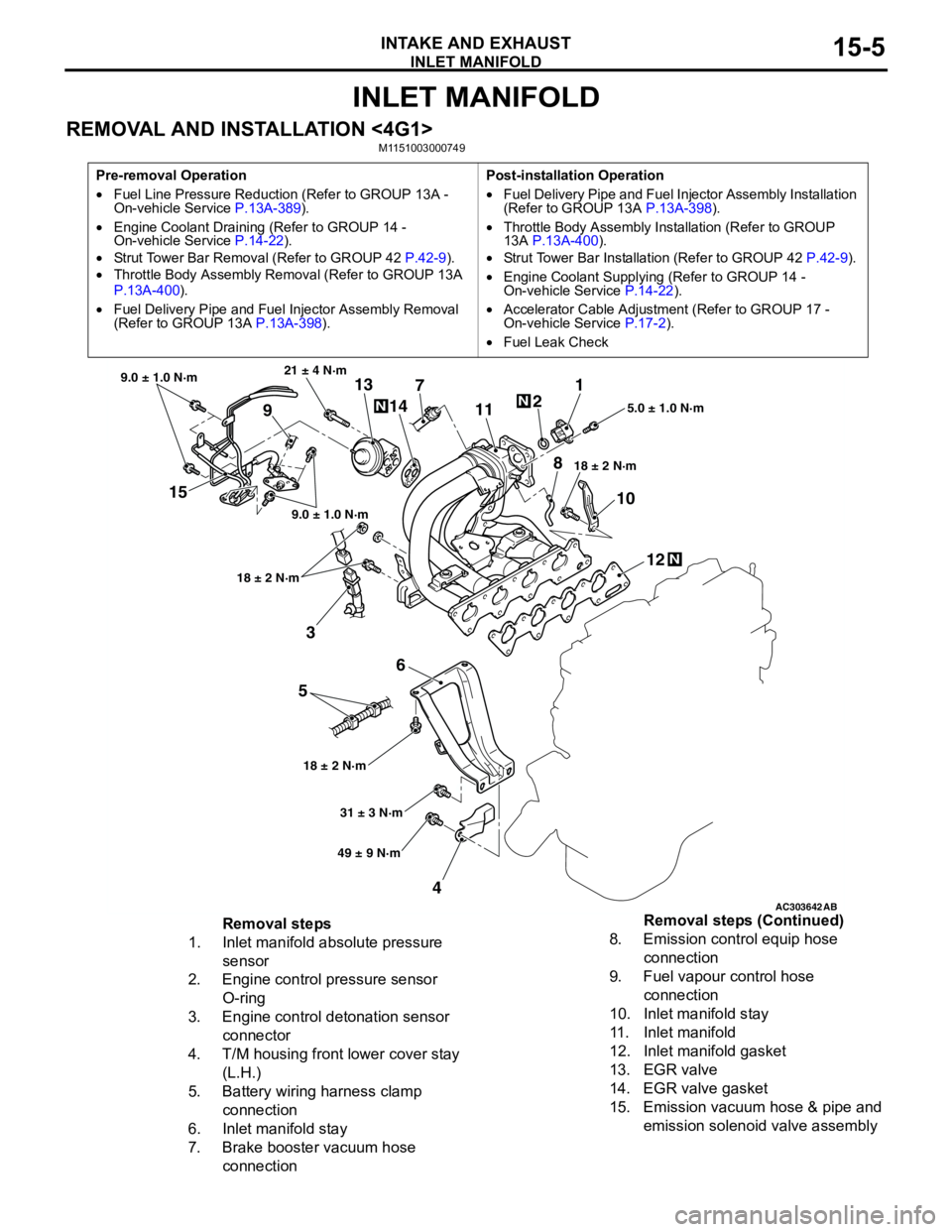
REMOVAL AND INSTALLATION <4G1>M1151003000749
Pre-removal Operation
•Fuel Line Pressure Reduction (Refer to GROUP 13A -
On-vehicle Service P.13A-389).
•Engine Coolant Draining (Refer to GROUP 14 -
On-vehicle Service P.14-22).
•Strut Tower Bar Removal (Refer to GROUP 42 P.42-9).
•Throttle Body Assembly Removal (Refer to GROUP 13A
P.13A-400).
•Fuel Delivery Pipe and Fuel Injector Assembly Removal
(Refer to GROUP 13A P.13A-398).Post-installation Operation
•Fuel Delivery Pipe and Fuel Injector Assembly Installation
(Refer to GROUP 13A P.13A-398).
•Throttle Body Assembly Installation (Refer to GROUP
13A P.13A-400).
•Strut Tower Bar Installation (Refer to GROUP 42 P.42-9).
•Engine Coolant Supplying (Refer to GROUP 14 -
On-vehicle Service P.14-22).
•Accelerator Cable Adjustment (Refer to GROUP 17 -
On-vehicle Service P.17-2).
•Fuel Leak Check
AC303642AB
15
3
6
5
412 10 71
2
11
913
14
21 ± 4 N·m
9.0 ± 1.0 N·m
9.0 ± 1.0 N·m
18 ± 2 N·m
18 ± 2 N·m18 ± 2 N·m5.0 ± 1.0 N·m
31 ± 3 N·m
49 ± 9 N·m
N
N
N
8
Removal steps
1. Inlet manifold absolute pressure
sensor
2. Engine control pressure sensor
O-ring
3. Engine control detonation sensor
connector
4. T/M housing front lower cover stay
(L.H.)
5. Battery wiring harness clamp
connection
6. Inlet manifold stay
7. Brake booster vacuum hose
connection8. Emission control equip hose
connection
9. Fuel vapour control hose
connection
10. Inlet manifold stay
11. Inlet manifold
12. Inlet manifold gasket
13. EGR valve
14. EGR valve gasket
15. Emission vacuum hose & pipe and
emission solenoid valve assembly Removal steps (Continued)
Page 58 of 788
INLET MANIFOLD
INTAKE AND EXHAUST15-6
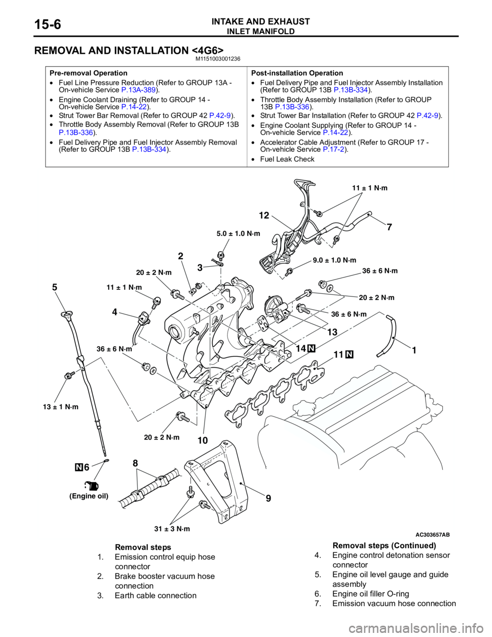
REMOVAL AND INSTALLATION <4G6>M1151003001236
Pre-removal Operation
•Fuel Line Pressure Reduction (Refer to GROUP 13A -
On-vehicle Service P.13A-389).
•Engine Coolant Draining (Refer to GROUP 14 -
On-vehicle Service P.14-22).
•Strut Tower Bar Removal (Refer to GROUP 42 P.42-9).
•Throttle Body Assembly Removal (Refer to GROUP 13B
P.13B-336).
•Fuel Delivery Pipe and Fuel Injector Assembly Removal
(Refer to GROUP 13B P.13B-334).Post-installation Operation
•Fuel Delivery Pipe and Fuel Injector Assembly Installation
(Refer to GROUP 13B P.13B-334).
•Throttle Body Assembly Installation (Refer to GROUP
13B P.13B-336).
•Strut Tower Bar Installation (Refer to GROUP 42 P.42-9).
•Engine Coolant Supplying (Refer to GROUP 14 -
On-vehicle Service P.14-22).
•Accelerator Cable Adjustment (Refer to GROUP 17 -
On-vehicle Service P.17-2).
•Fuel Leak Check
AC303657
9.0 ± 1.0 N·m11 ± 1 N·m
20 ± 2 N·m
31 ± 3 N·m 36 ± 6 N·m
20 ± 2 N·m
20 ± 2 N·m
36 ± 6 N·m
36 ± 6 N·m
11
9 10 212
N1413N
AB
5.0 ± 1.0 N·m
3
1
11 ± 1 N·m
4
N
13 ± 1 N·m
5
6
(Engine oil)
7
8
Removal steps
1. Emission control equip hose
connector
2. Brake booster vacuum hose
connection
3. Earth cable connection4. Engine control detonation sensor
connector
5. Engine oil level gauge and guide
assembly
6. Engine oil filler O-ring
7. Emission vacuum hose connectionRemoval steps (Continued)
Page 77 of 788
CHARGING SYSTEM
ENGINE ELECTRICAL16-13
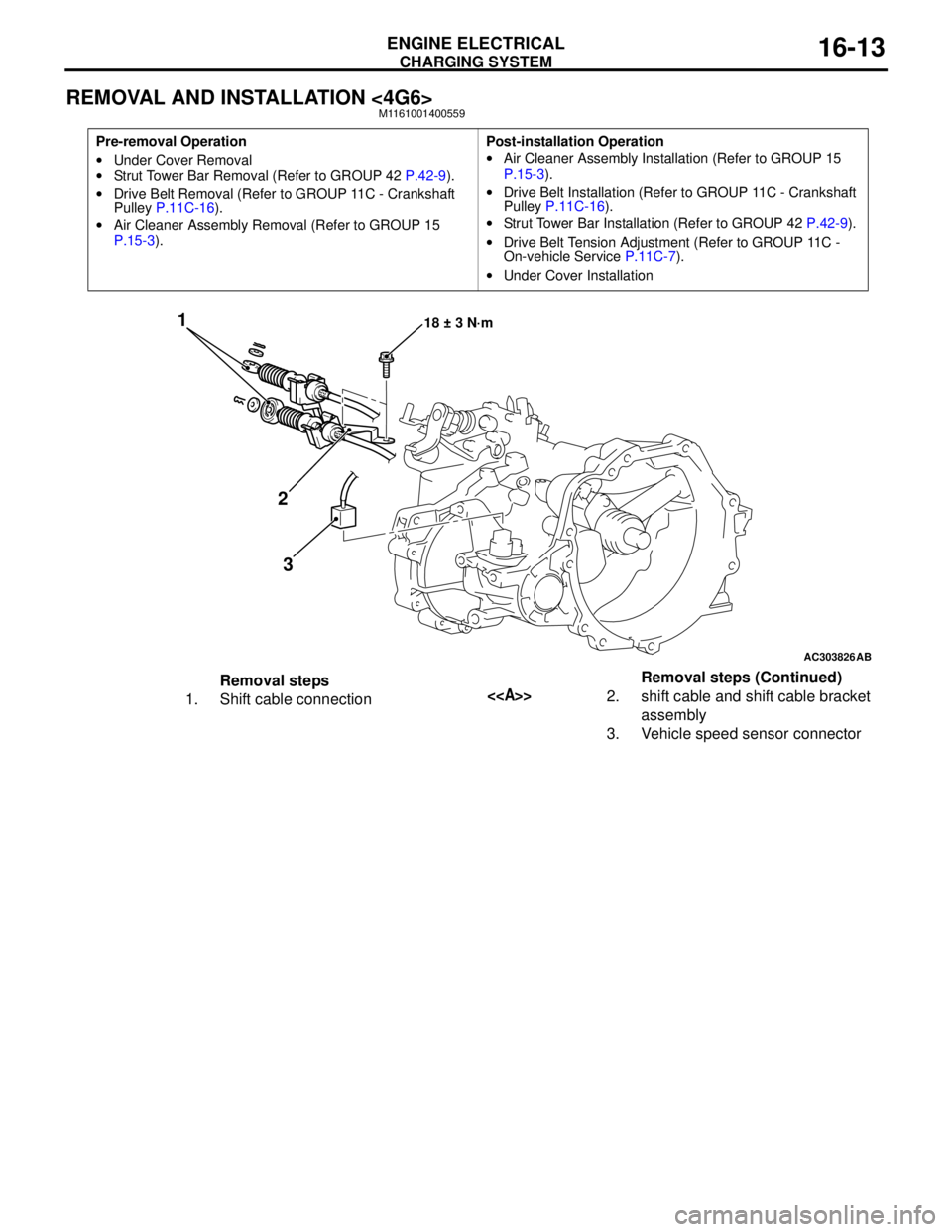
REMOVAL AND INSTALLATION <4G6>M1161001400559
Pre-removal Operation
•Under Cover Removal
•Strut Tower Bar Removal (Refer to GROUP 42 P.42-9).
•Drive Belt Removal (Refer to GROUP 11C - Crankshaft
Pulley P.11C-16).
•Air Cleaner Assembly Removal (Refer to GROUP 15
P.15-3).Post-installation Operation
•Air Cleaner Assembly Installation (Refer to GROUP 15
P.15-3).
•Drive Belt Installation (Refer to GROUP 11C - Crankshaft
Pulley P.11C-16).
•Strut Tower Bar Installation (Refer to GROUP 42 P.42-9).
•Drive Belt Tension Adjustment (Refer to GROUP 11C -
On-vehicle Service P.11C-7).
•Under Cover Installation
AC303826
1
2
318 ± 3 N·m
AB
Removal steps
1. Shift cable connection<>2. shift cable and shift cable bracket
assembly
3. Vehicle speed sensor connectorRemoval steps (Continued)
Page 142 of 788
FRONT AXLE HUB ASSEMBLY
FRONT AXLE26-10
<
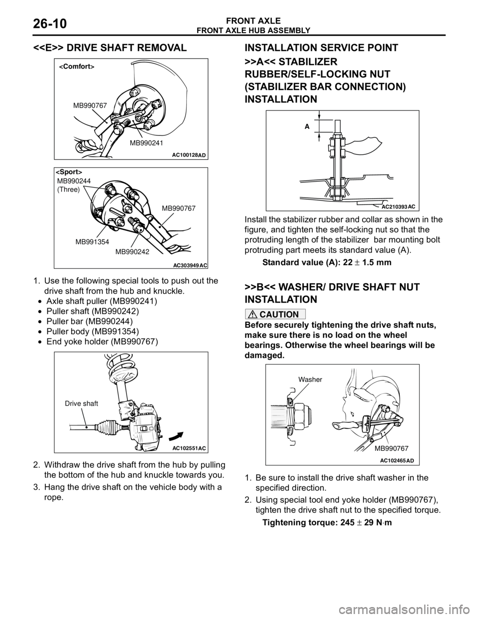
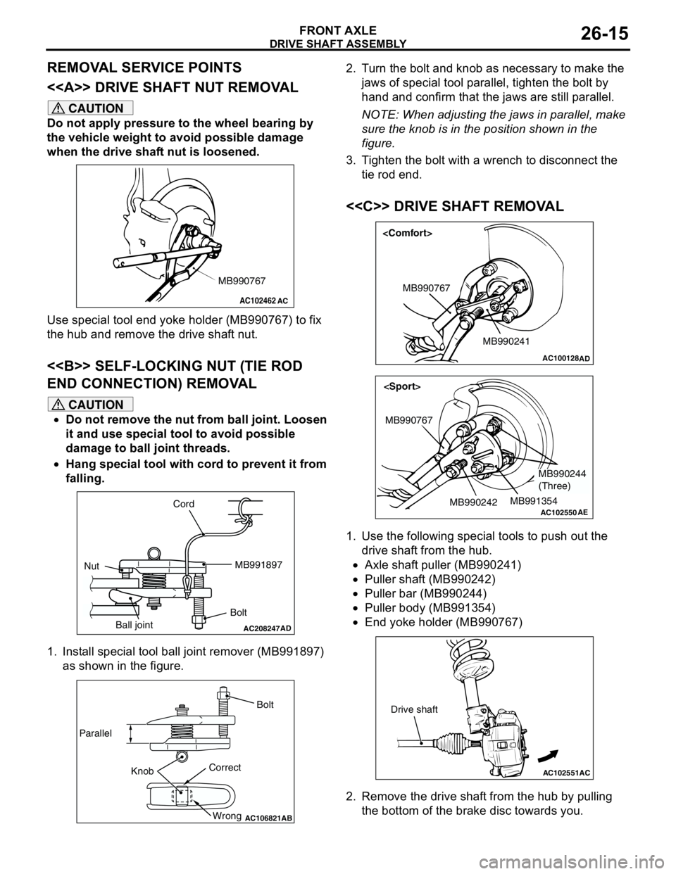
1. Use the following special tools to push out the
drive shaft from the hub and knuckle.
•Axle shaft puller (MB990241)
•Puller shaft (MB990242)
•Puller bar (MB990244)
•Puller body (MB991354)
•End yoke holder (MB990767)
2. Withdraw the drive shaft from the hub by pulling
the bottom of the hub and knuckle towards you.
3. Hang the drive shaft on the vehicle body with a
rope.
INSTALLATION SERVICE POINT
>>A<< STABILIZER
RUBBER/SELF-LOCKING NUT
(STABILIZER BAR CONNECTION)
INSTALLATION
Install the stabilizer rubber and collar as shown in the
figure, and tighten the self-locking nut so that the
protruding length of the stabilizer bar mounting bolt
protruding part meets its standard value (A).
Standard value (A): 22 ± 1.5 mm
>>B<< WASHER/ DRIVE SHAFT NUT
INSTALLATION
CAUTION
Before securely tightening the drive shaft nuts,
make sure there is no load on the wheel
bearings. Otherwise the wheel bearings will be
damaged.
1. Be sure to install the drive shaft washer in the
specified direction.
2. Using special tool end yoke holder (MB990767),
tighten the drive shaft nut to the specified torque.
Tightening torque: 245 ± 29 N⋅m
AC100128
MB990241 MB990767
AD
AC303949
MB990244
(Three)
MB990767
MB990242 MB991354
AC
AC102551
AC
Drive shaft
AC210393AC
A
AC102465AD
MB990767 Washer
Page 147 of 788
Page 279 of 788
42-1
GROUP 42
BODY
CONTENTS
HOOD . . . . . . . . . . . . . . . . . . . . .
42-3
ON-VEHICLE SERVICE. . . . . . . . .
42-3
ADJUSTMENT OF CLEARANCE
AROUND HOOD . . . . . . . . . . . . . . . . . . 42-3
ADJUSTMENT OF ALIGNMENT OF
HOOD STEPPED PORTION AND
HOOD STRIKER . . . . . . . . . . . . . . . . . . 42-3
ADJUSTMENT OF HOOD HEIGHT . . . 42-3
HOOD . . . . . . . . . . . . . . . . . . . . . . .42-4
REMOVAL AND INSTALLATION . . . . . 42-4
FENDER . . . . . . . . . . . . . . . . . . .42-5
SPECIAL TOOL . . . . . . . . . . . . . . .
42-5
FENDER . . . . . . . . . . . . . . . . . . . . .42-6
REMOVAL AND INSTALLATION . . . . . 42-6
FUEL FILLER LID . . . . . . . . . . .42-8
REMOVAL AND INSTALLATION .
42-8
STRUT TOWER BAR . . . . . . . .42-9
REMOVAL AND INSTALLATION .
42-9
WINDOW GLASS . . . . . . . . . . . 42-9
ADHESIVE . . . . . . . . . . . . . . . . . . .
42-9
SPECIAL TOOLS . . . . . . . . . . . . . .42-9
WINDOW REPAIR . . . . . . . . . . . . .42-10
WINDSHIELD . . . . . . . . . . . . . . . . .42-12
REMOVAL AND INSTALLATION . . . . . . 42-12
REAR WINDOW GLASS . . . . . . . .42-16
REMOVAL AND INSTALLATION . . . . . . 42-16
QUARTER WINDOW GLASS . . . .42-19
REMOVAL AND INSTALLATION . . . . . . 42-19
TAILGATE WINDOW GLASS . . . .42-22
REMOVAL AND INSTALLATION . . . . . . 42-22
DOOR . . . . . . . . . . . . . . . . . . . . 42-25
SERVICE SPECIFICATIONS . . . . .
42-25
SEALANT . . . . . . . . . . . . . . . . . . . .42-25
SPECIAL TOOLS . . . . . . . . . . . . . .42-25
Continued on next page
Page 287 of 788
STRUT TOWER BAR
BODY42-9
STRUT TOWER BAR
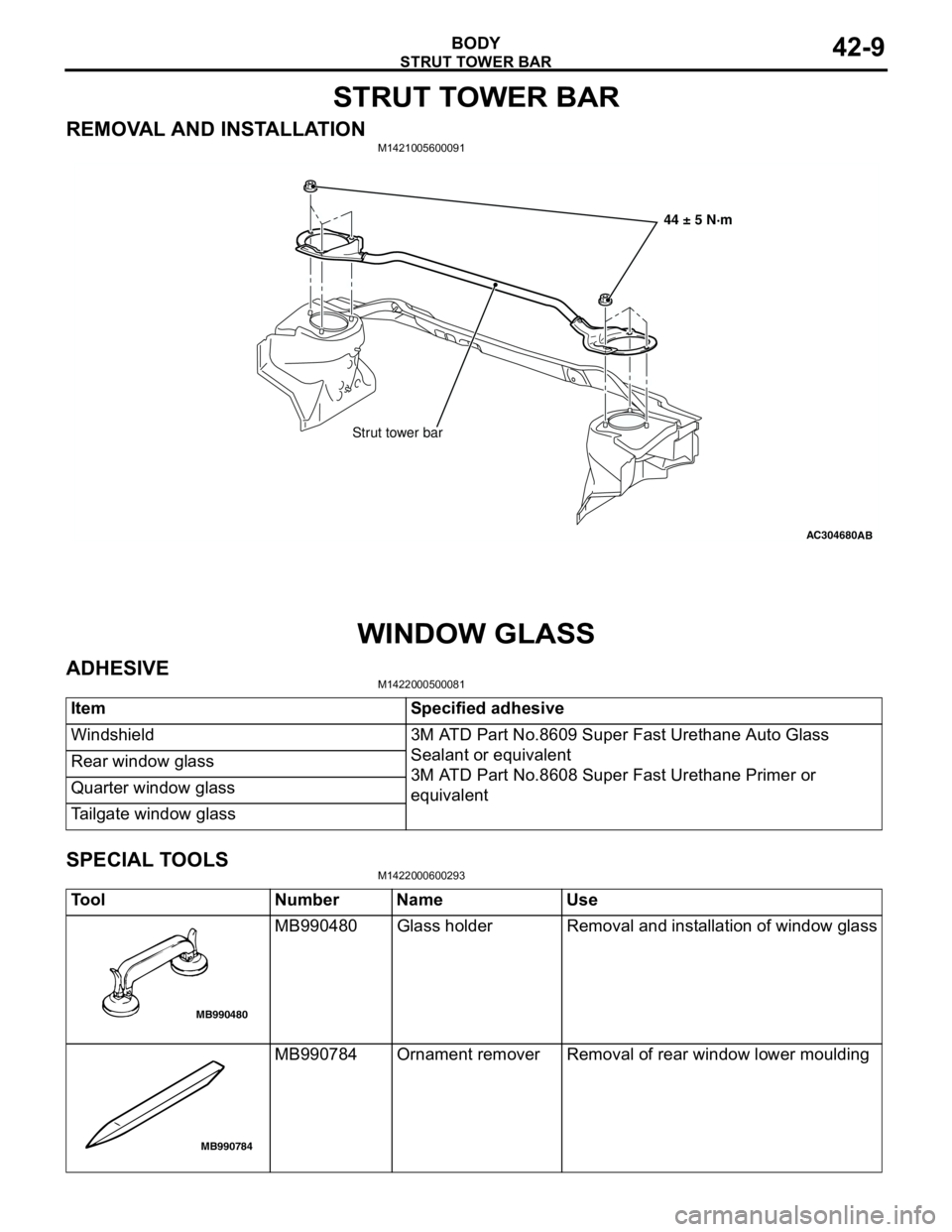
REMOVAL AND INSTALLATIONM1421005600091
WINDOW GLASS
ADHESIVEM1422000500081
SPECIAL TOOLSM1422000600293
AC304680AB
Strut tower bar44 ± 5 N·m
Item Specified adhesive
Windshield 3M ATD Part No.8609 Super Fast Urethane Auto Glass
Sealant or equivalent
3M ATD Part No.8608 Super Fast Urethane Primer or
equivalent Rear window glass
Quarter window glass
Tailgate window glass
Tool Number Name Use
MB990480 Glass holder Removal and installation of window glass
MB990784 Ornament remover Removal of rear window lower moulding
MB990480
MB990784
Page 305 of 788
DOOR
BODY42-27
ON-VEHICLE SERVICE
DOOR FIT ADJUSTMENTM1423001100175
CAUTION
•Attach protection tape to the fender and door
edges where the hinge is installed.
•Do not rotate special tool door adjusting
wrench (MB991164) with a torque of over 98
N⋅m
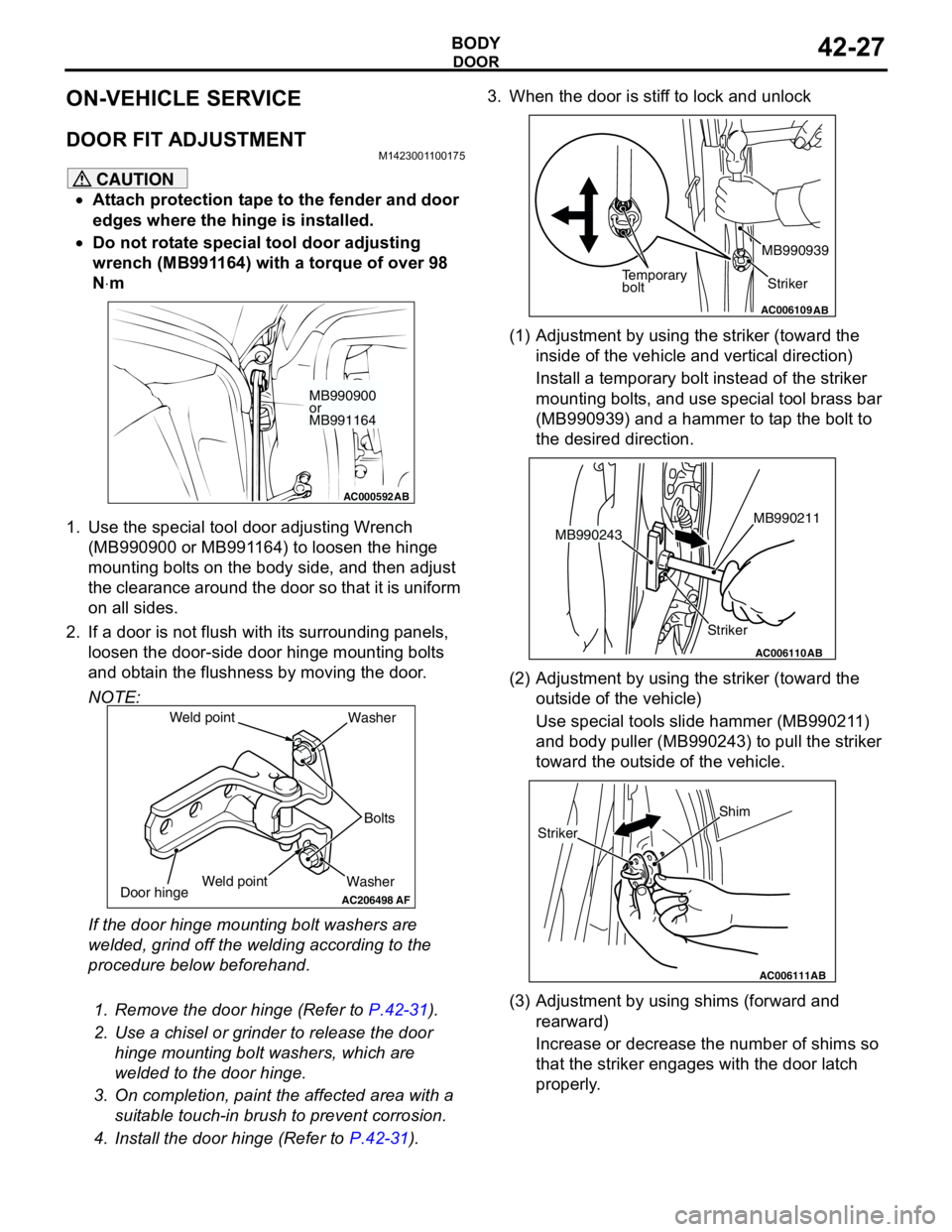
1. Use the special tool door adjusting Wrench
(MB990900 or MB991164) to loosen the hinge
mounting bolts on the body side, and then adjust
the clearance around the door so that it is uniform
on all sides.
2. If a door is not flush with its surrounding panels,
loosen the door-side door hinge mounting bolts
and obtain the flushness by moving the door.
NOTE:
If the door hinge mounting bolt washers are
welded, grind off the welding according to the
procedure below beforehand.
.
1. Remove the door hinge (Refer to P.42-31).
2. Use a chisel or grinder to release the door
hinge mounting bolt washers, which are
welded to the door hinge.
3. On completion, paint the affected area with a
suitable touch-in brush to prevent corrosion.
4. Install the door hinge (Refer to P.42-31).3. When the door is stiff to lock and unlock
(1) Adjustment by using the striker (toward the
inside of the vehicle and vertical direction)
Install a temporary bolt instead of the striker
mounting bolts, and use special tool brass bar
(MB990939) and a hammer to tap the bolt to
the desired direction.
(2) Adjustment by using the striker (toward the
outside of the vehicle)
Use special tools slide hammer (MB990211)
and body puller (MB990243) to pull the striker
toward the outside of the vehicle.
(3) Adjustment by using shims (forward and
rearward)
Increase or decrease the number of shims so
that the striker engages with the door latch
properly.
AC000592
MB990900
or
MB991164
AB
AC206498
WasherBolts Washer
Door hinge
AF
Weld point Weld point
AC006109AB
Temporary
boltStriker MB990939
AC006110
StrikerMB990211
MB990243
AB
AC006111AB
Shim
Striker