boot MITSUBISHI LANCER 2005 Workshop Manual
[x] Cancel search | Manufacturer: MITSUBISHI, Model Year: 2005, Model line: LANCER, Model: MITSUBISHI LANCER 2005Pages: 788, PDF Size: 45.98 MB
Page 133 of 788
26-1
GROUP 26
FRONT AXLE
CONTENTS
GENERAL INFORMATION . . . . . . . .26-2
SERVICE SPECIFICATIONS . . . . . . .26-3
LUBRICANTS . . . . . . . . . . . . . . . . . .26-3
SPECIAL TOOLS . . . . . . . . . . . . . . . .26-4
ON-VEHICLE SERVICE . . . . . . . . . . .26-7
WHEEL BEARING AXIAL PLAY CHECK . . 26-7
HUB BOLT REPLACEMENT . . . . . . . . . . . 26-7
FRONT AXLE HUB ASSEMBLY . . . .26-8
REMOVAL AND INSTALLATION . . . . . . . . 26-8
INSPECTION . . . . . . . . . . . . . . . . . . . . . . . . 26-11
DISASSEMBLY AND REASSEMBLY . . . . . 26-11
INSPECTION . . . . . . . . . . . . . . . . . . . . . . . . 26-13
DRIVE SHAFT ASSEMBLY . . . . . . . .26-14
REMOVAL AND INSTALLATION . . . . . . . . 26-14
DISASSEMBLY AND REASSEMBLY . . . . . 26-18
INSPECTION . . . . . . . . . . . . . . . . . . . . . . . . 26-21
BJ BOOT (RESIN BOOT)
REPLACEMENT . . . . . . . . . . . . . . . . . . . . . 26-21
Page 135 of 788
SERVICE SPECIFICATIONS
FRONT AXLE26-3
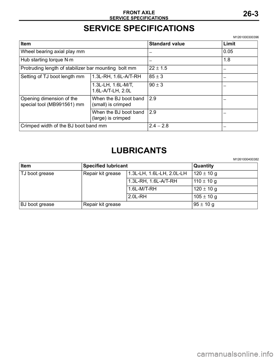
SERVICE SPECIFICATIONS
M1261000300396
LUBRICANTS
M1261000400382
Item Standard value Limit
Wheel bearing axial play mm
−0.05
Hub starting torque N⋅m
−1.8
Protruding length of stabilizer bar mounting bolt mm 22 ± 1.5
−
Setting of TJ boot length mm 1.3L-RH, 1.6L-A/T-RH 85 ± 3
−
1.3L-LH, 1.6L-M/T,
1.6L-A/T-LH, 2.0L90 ± 3
−
Opening dimension of the
special tool (MB991561) mmWhen the BJ boot band
(small) is crimped2.9
−
When the BJ boot band
(large) is crimped2.9
−
Crimped width of the BJ boot band mm 2.4 − 2.8
−
Item Specified lubricant Quantity
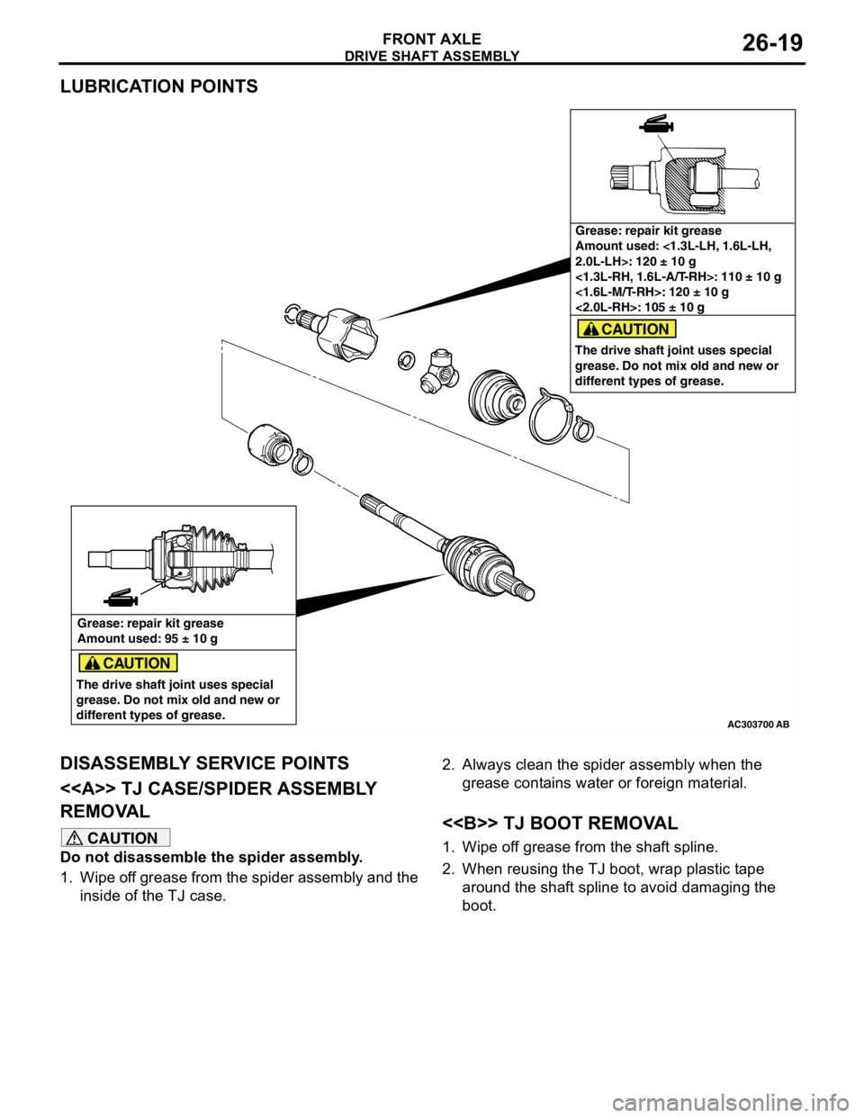
TJ boot grease Repair kit grease 1.3L-LH, 1.6L-LH, 2.0L-LH 120 ± 10 g
1.3L-RH, 1.6L-A/T-RH 110 ± 10 g
1.6L-M/T-RH 120 ± 10 g
2.0L-RH 105 ± 10 g
BJ boot grease Repair kit grease 95 ± 10 g
Page 137 of 788
SPECIAL TOOLS
FRONT AXLE26-5
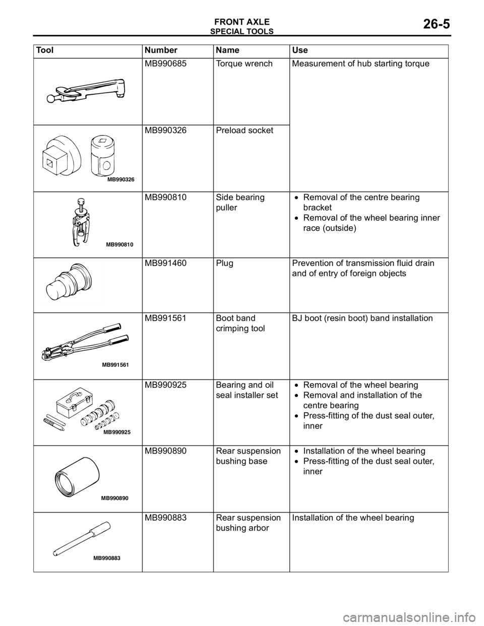
MB990685 Torque wrench Measurement of hub starting torque
MB990326 Preload socket
MB990810 Side bearing
puller•Removal of the centre bearing
bracket
•Removal of the wheel bearing inner
race (outside)
MB991460 Plug Prevention of transmission fluid drain
and of entry of foreign objects
MB991561 Boot band
crimping toolBJ boot (resin boot) band installation
MB990925 Bearing and oil
seal installer set•Removal of the wheel bearing
•Removal and installation of the
centre bearing
•Press-fitting of the dust seal outer,
inner
MB990890 Rear suspension
bushing base•Installation of the wheel bearing
•Press-fitting of the dust seal outer,
inner
MB990883 Rear suspension
bushing arborInstallation of the wheel bearing Tool Number Name Use
MB990326
MB990810
MB991561
MB990925
MB990890
MB990883
Page 150 of 788
DRIVE SHAFT ASSEMBLY
FRONT AXLE26-18
DISASSEMBLY AND REASSEMBLYM1261003700456
CAUTION
•Be careful not to damage the ABS rotor, which is attached to the BJ outer race during disassembly
and reassembly.
•Never disassemble the BJ assembly except when replacing the BJ boot.
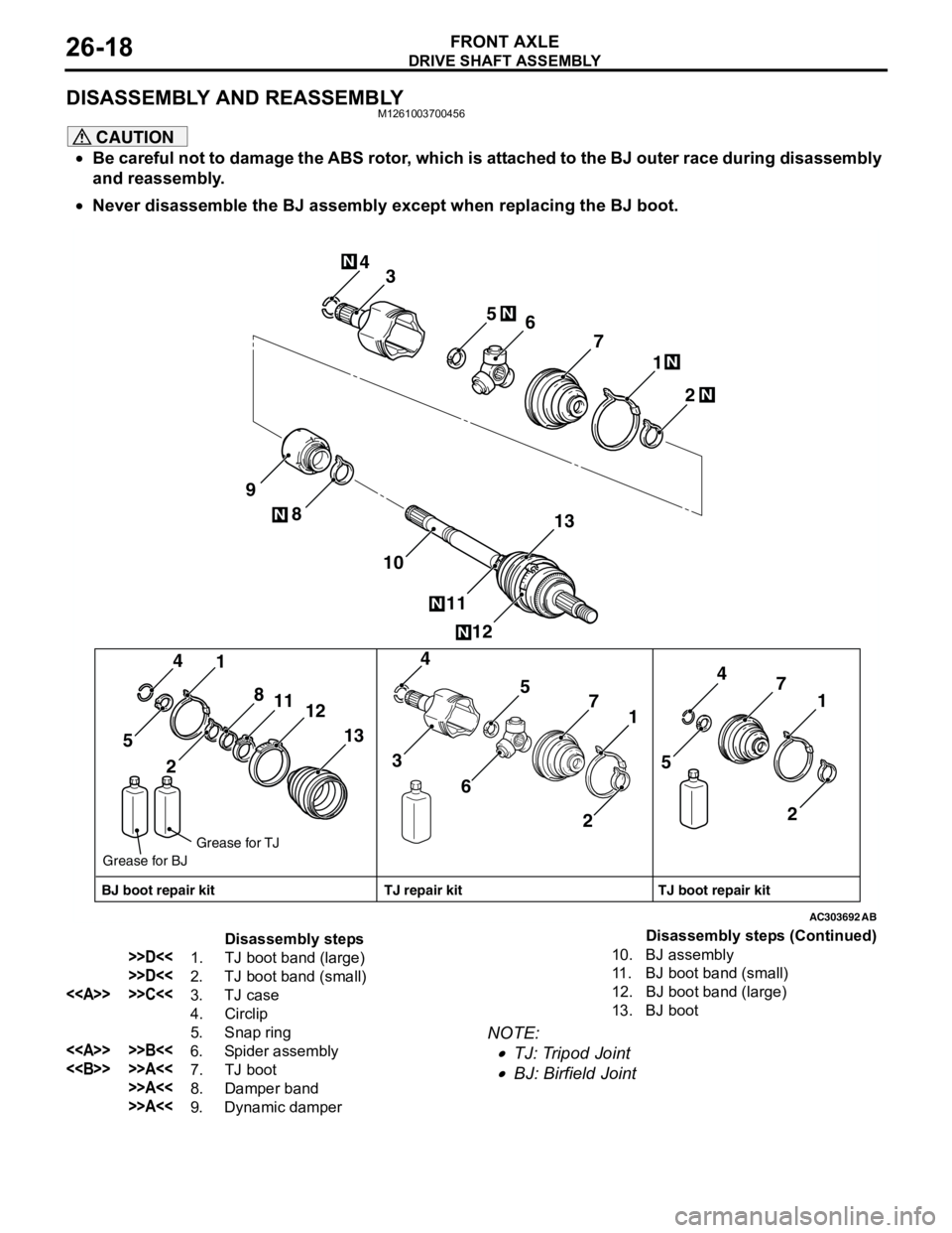
NOTE: .
•TJ: Tripod Joint
•BJ: Birfield Joint
AC303692
2 1 4
12 8
11 10 97
13 6 5N
N
N
3
N
N
21 4
13 8
11
12
5
21 4
7
65
3
21 4
7
5
AB
N
N
BJ boot repair kitTJ boot repair kit TJ repair kit Grease for TJ
Grease for BJ
Disassembly steps
>>D<<1. TJ boot band (large)
>>D<<2. TJ boot band (small)
<> >>C<<3. TJ case
4. Circlip
5. Snap ring
<> >>B<<6. Spider assembly
<> >>A<<7. TJ boot
>>A<<8. Damper band
>>A<<9. Dynamic damper10. BJ assembly
11. BJ boot band (small)
12. BJ boot band (large)
13. BJ bootDisassembly steps (Continued)
Page 151 of 788
Page 152 of 788
DRIVE SHAFT ASSEMBLY
FRONT AXLE26-20
REASSEMBLY SERVICE POINTS
>>A<< DYNAMIC DAMPER/DAMPER
BAND/TJ BOOT INSTALLATION
CAUTION
There should be no grease adhered to the rubber
part of the dynamic damper.
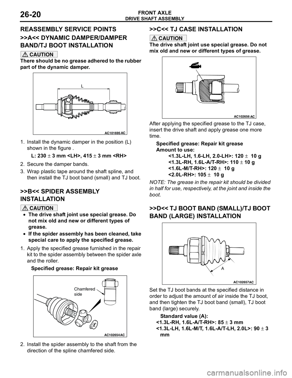
1. Install the dynamic damper in the position (L)
shown in the figure .
L: 230 ± 3 mm
2. Secure the damper bands.
3. Wrap plastic tape around the shaft spline, and
then install the TJ boot band (small) and TJ boot.
>>B<< SPIDER ASSEMBLY
INSTALLATION
CAUTION
•The drive shaft joint use special grease. Do
not mix old and new or different types of
grease.
•If the spider assembly has been cleaned, take
special care to apply the specified grease.
1. Apply the specified grease furnished in the repair
kit to the spider assembly between the spider axle
and the roller.
Specified grease: Repair kit grease
2. Install the spider assembly to the shaft from the
direction of the spline chamfered side.
>>C<< TJ CASE INSTALLATION
CAUTION
The drive shaft joint use special grease. Do not
mix old and new or different types of grease.
After applying the specified grease to the TJ case,
insert the drive shaft and apply grease one more
time.
Specified grease: Repair kit grease
Amount to use:
<1.3L-LH, 1.6-LH, 2.0-LH>: 120 ± 10 g
<1.3L-RH, 1.6L-A/T-RH>: 110 ± 10 g
<1.6L-M/T-RH>: 120 ± 10 g
<2.0L-RH>: 105 ± 10 g
NOTE: The grease in the repair kit should be divided
in half for use, respectively, at the joint and inside the
boot.
>>D<< TJ BOOT BAND (SMALL)/TJ BOOT
BAND (LARGE) INSTALLATION
Set the TJ boot bands at the specified distance in
order to adjust the amount of air inside the TJ boot,
and then tighten the TJ boot band (small), TJ boot
band (large) securely.
Standard value (A):
<1.3L-RH, 1.6L-A/T-RH>: 85 ± 3 mm
<1.3L-LH, 1.6L-M/T, 1.6L-A/T-LH, 2.0L>: 90 ± 3
mm
AC101695AC
L
AC102654AC
Chamfered
side
AC102656AC
AC102657
A
AC
Page 153 of 788
DRIVE SHAFT ASSEMBLY
FRONT AXLE26-21
INSPECTIONM1261003800130
•Check the drive shaft for damage, bending or
corrosion.
•Check the drive shaft spline part for wear or
damage.
•Check the spider assembly for roller rotation,
wear or corrosion.
•Check the groove inside TJ case for wear or
corrosion.
•Check the dynamic damper for damage or
cracking.
•Check the boots for deterioration, damage or
cracking.
BJ BOOT (RESIN BOOT) REPLACEMENTM1261005200361
1. Remove the boot bands (large and small).
NOTE: The boot bands cannot be re-used.
2. Remove the BJ boot.
3. Wrap a plastic tape around the shaft spline, and
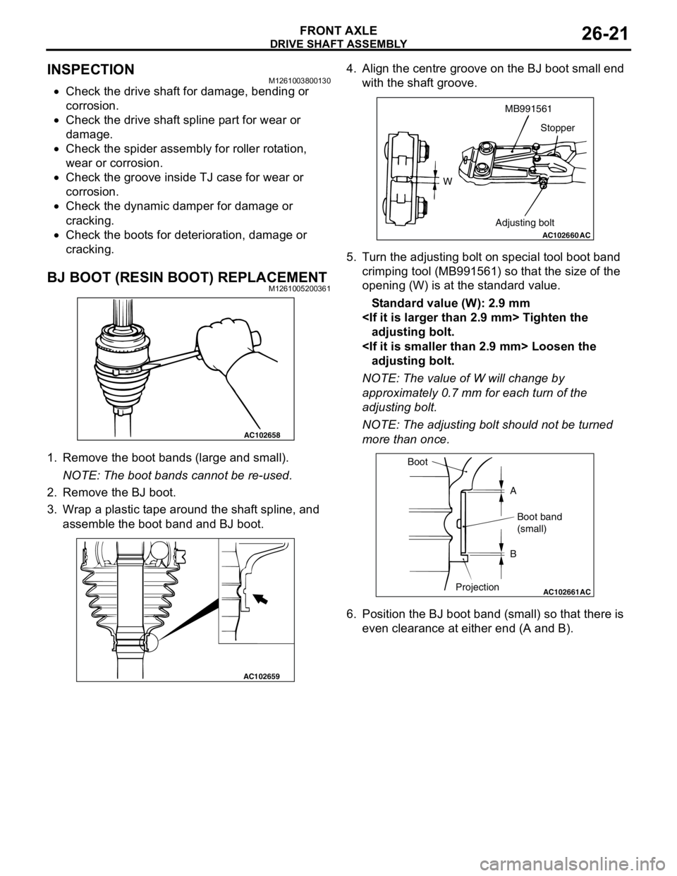
assemble the boot band and BJ boot.4. Align the centre groove on the BJ boot small end
with the shaft groove.
5. Turn the adjusting bolt on special tool boot band
crimping tool (MB991561) so that the size of the
opening (W) is at the standard value.
Standard value (W): 2.9 mm
adjusting bolt.
adjusting bolt.
NOTE: The value of W will change by
approximately 0.7 mm for each turn of the
adjusting bolt.
NOTE: The adjusting bolt should not be turned
more than once.
6. Position the BJ boot band (small) so that there is
even clearance at either end (A and B).
AC102658
AC102659
AC102660
WMB991561
Stopper
Adjusting bolt
AC
AC102661AC
Boot
A
Boot band
(small)
B
Projection
Page 154 of 788
DRIVE SHAFT ASSEMBLY
FRONT AXLE26-22
CAUTION
•Secure the drive shaft in an upright position
and clamp part of the boot band to be crimped
securely in the jaws of special tool.
•Crimp the boot band until special tool
touches the stopper.
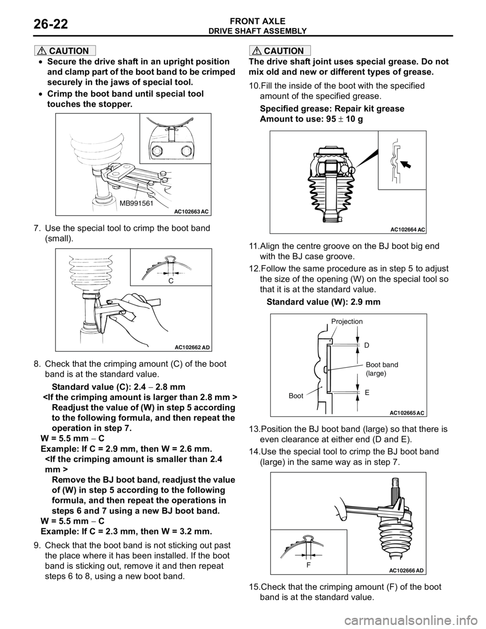
7. Use the special tool to crimp the boot band
(small).
8. Check that the crimping amount (C) of the boot
band is at the standard value.
Standard value (C): 2.4 − 2.8 mm
Readjust the value of (W) in step 5 according
to the following formula, and then repeat the
operation in step 7.
W = 5.5 mm − C
Example: If C = 2.9 mm, then W = 2.6 mm.
Remove the BJ boot band, readjust the value
of (W) in step 5 according to the following
formula, and then repeat the operations in
steps 6 and 7 using a new BJ boot band.
W = 5.5 mm − C
Example: If C = 2.3 mm, then W = 3.2 mm.
9. Check that the boot band is not sticking out past
the place where it has been installed. If the boot
band is sticking out, remove it and then repeat
steps 6 to 8, using a new boot band.
CAUTION
The drive shaft joint uses special grease. Do not
mix old and new or different types of grease.
10.Fill the inside of the boot with the specified
amount of the specified grease.
Specified grease: Repair kit grease
Amount to use: 95 ± 10 g
11.Align the centre groove on the BJ boot big end
with the BJ case groove.
12.Follow the same procedure as in step 5 to adjust
the size of the opening (W) on the special tool so
that it is at the standard value.
Standard value (W): 2.9 mm
13.Position the BJ boot band (large) so that there is
even clearance at either end (D and E).
14.Use the special tool to crimp the BJ boot band
(large) in the same way as in step 7.
15.Check that the crimping amount (F) of the boot
band is at the standard value.
AC102663 ACMB991561
AC102662
C
AD
AC102664AC
AC102665
AC
BootProjection
Boot band
(large) D
E
AC102666FAD
Page 155 of 788
DRIVE SHAFT ASSEMBLY
FRONT AXLE26-23
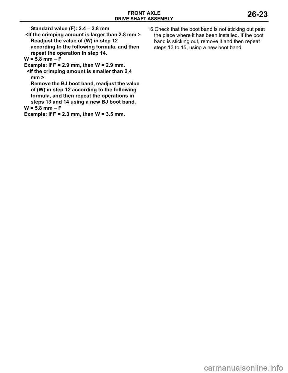
Standard value (F): 2.4 − 2.8 mm
Readjust the value of (W) in step 12
according to the following formula, and then
repeat the operation in step 14.
W = 5.8 mm − F
Example: If F = 2.9 mm, then W = 2.9 mm.
Remove the BJ boot band, readjust the value
of (W) in step 12 according to the following
formula, and then repeat the operations in
steps 13 and 14 using a new BJ boot band.
W = 5.8 mm − F
Example: If F = 2.3 mm, then W = 3.5 mm.16.Check that the boot band is not sticking out past
the place where it has been installed. If the boot
band is sticking out, remove it and then repeat
steps 13 to 15, using a new boot band.
Page 240 of 788
SERVICE SPECIFICATIONS
POWER STEERING37-6
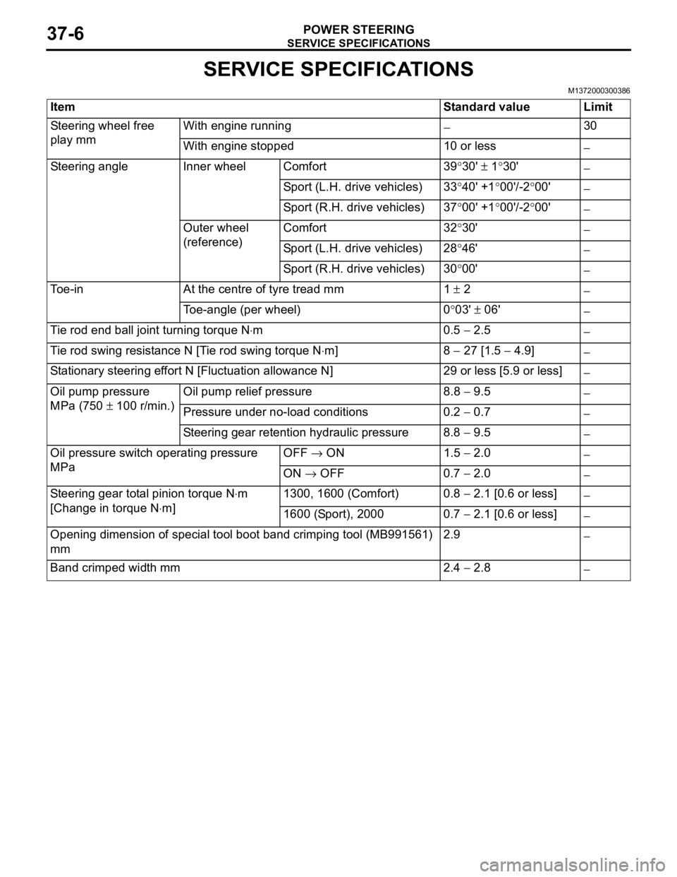
SERVICE SPECIFICATIONS
M1372000300386
Item Standard value Limit
Steering wheel free
play mmWith engine running
−30
With engine stopped 10 or less
−
Steering angle Inner wheel Comfort 39°30' ± 1°30'
−
Sport (L.H. drive vehicles) 33°40' +1°00'/-2°00'
−
Sport (R.H. drive vehicles) 37°00' +1°00'/-2°00'
−
Outer wheel
(reference)Comfort 32°30'
−
Sport (L.H. drive vehicles) 28°46'
−
Sport (R.H. drive vehicles) 30°00'
−
Toe-in At the centre of tyre tread mm 1 ± 2
−
Toe-angle (per wheel) 0°03' ± 06'
−
Tie rod end ball joint turning torque N⋅m0.5 − 2.5
−
Tie rod swing resistance N [Tie rod swing torque N⋅m] 8 − 27 [1.5 − 4.9]
−
Stationary steering effort N [Fluctuation allowance N] 29 or less [5.9 or less]
−
Oil pump pressure
MPa (750 ± 100 r/min.)Oil pump relief pressure 8.8 − 9.5
−
Pressure under no-load conditions 0.2 − 0.7
−
Steering gear retention hydraulic pressure 8.8 − 9.5
−
Oil pressure switch operating pressure
MPaOFF → ON 1.5 − 2.0
−
ON → OFF 0.7 − 2.0
−
Steering gear total pinion torque N⋅m
[Change in torque N⋅m]1300, 1600 (Comfort) 0.8 − 2.1 [0.6 or less]
−
1600 (Sport), 2000 0.7 − 2.1 [0.6 or less]
−
Opening dimension of special tool boot band crimping tool (MB991561)
mm2.9
−
Band crimped width mm 2.4 − 2.8
−