water temperature sensor MITSUBISHI LANCER 2005 Workshop Manual
[x] Cancel search | Manufacturer: MITSUBISHI, Model Year: 2005, Model line: LANCER, Model: MITSUBISHI LANCER 2005Pages: 788, PDF Size: 45.98 MB
Page 21 of 788
TROUBLESHOOTING
ENGINE COOLING14-7
CIRCUIT OPERATION
•The cooling fan motor drive control unit is
powered from fusible link (2).
•The engine-ECU
uses input signals from the A/C switch, the
water temperature sensor unit and the vehicle
speed sensor
sensor to control the speed of the cooling
fan motor (L.H.) and the cooling fan motor (R.H.)
<4G1 (Vehicles with A/C)> or A/C condenser fan
motor <4G6>.
•The engine-ECU
controls the cooling fan motor drive control
unit to activate the cooling fan motor (L.H.) and
the cooling fan motor (R.H.) <4G1 (Vehicles with
A/C)> or A/C condenser fan motor <4G6>.
TECHNICAL DESCRIPTION
•The cause could be a malfunction of the cooling
fan motor drive control unit power supply or earth
circuit.
•If the communication line wiring harness between
the cooling fan motor drive control unit and the
engine-ECU
short-circuited to earth, the cooling fan motor
(L.H.) and the cooling fan motor (R.H.) <4G1
(Vehicles with A/C)> or the A/C condenser fan
motor <4G6> will not rotate.
•The cause could also be a malfunction of the
cooling fan motor (L.H.).
•The cause could also be a malfunction of imput
signal from the A/C switch, the water temperature
sensor unit and the vehicle speed sensor
or the output shaft speed sensor to the
engine-ECU
•The cause could also be a malfunction of the
cooling fan motor drive control unit or the
engine-ECU
TROUBLESHOOTING HINTS
•Malfunction of fusible link (2)
•Malfunction of fan control relay
•Malfunction of cooling fan motor (L.H.)
•Malfunction of cooling fan motor drive control unit
•Malfunction of engine-ECU
engine-A/T-ECU
•Damaged wiring harness or connector
DIAGNOSIS
STEP 1. Check the cooling fan motor (L.H.).
Refer to P.14-25.
Q: Is the cooling fan motor (L.H.) in good condition?
YES :
Go to Step 2 .
NO : Replace the cooling fan motor (L.H.) (Refer
to P.14-35). Then go to Step 24 .
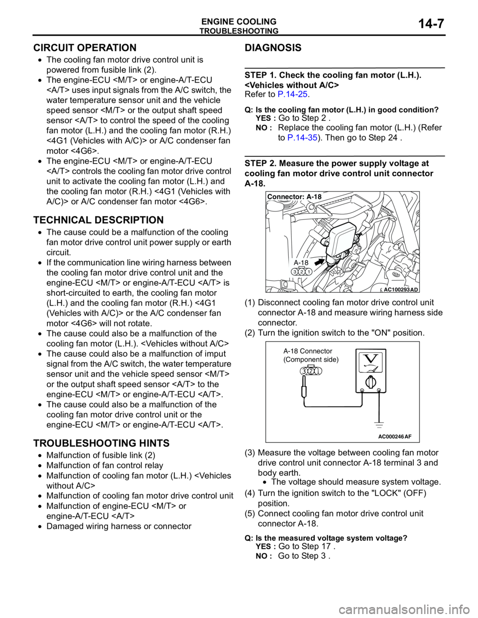
STEP 2. Measure the power supply voltage at
cooling fan motor drive control unit connector
A-18.
(1) Disconnect cooling fan motor drive control unit
connector A-18 and measure wiring harness side
connector.
(2) Turn the ignition switch to the "ON" position.
(3) Measure the voltage between cooling fan motor
drive control unit connector A-18 terminal 3 and
body earth.
•The voltage should measure system voltage.
(4) Turn the ignition switch to the "LOCK" (OFF)
position.
(5) Connect cooling fan motor drive control unit
connector A-18.
Q: Is the measured voltage system voltage?
YES :
Go to Step 17 .
NO : Go to Step 3 .
AC100293
A-18
321
Connector: A-18
AD
AC000246AF
A-18 Connector
(Component side)
Page 30 of 788
TROUBLESHOOTING
ENGINE COOLING14-16
INSPECTION PROCEDURE 2: Cooling Fan (L.H.) and Cooling Fan (R.H.) <4G1 (Vehicles with A/C)> or
A/C Condenser Fan <4G6> do not Change Speed or Stop
COOLING FAN (L.H.) AND COOLING FAN
(R.H.) OR A/C CONDENSER FAN DRIVE
CIRCUIT
Refer to P.14-6.
CIRCUIT OPERATION
Refer to P.14-6.
TECHNICAL DESCRIPTION
•If the communication line wiring harness between
the cooling fan motor drive control unit and the
engine-ECU
is open, the cooling fan motor (L.H.) and
the cooling fan motor (R.H.) <4G1 (Vehicles with
A/C)>, or the A/C condenser fan motor <4G6>
rotate to prevent the engine from overheating.
•If the system voltage is continuously supplied to
the cooling fan motor drive control unit by a fan
motor relay malfunction and a short circuit on the
cooling fan motor drive control unit power supply
wiring harness, the cooling fan motor (L.H.) and
the cooling fan motor (R.H.) <4G1 (Vehicles with
A/C)>, or the A/C condenser fan motor <4G6>
rotate.
•The cause could also be a malfunction of the
cooling fan motor (L.H.).
•The cause could also be a malfunction of input
signal from the A/C switch, the water temperature
sensor unit and the vehicle speed sensor
or the output shaft speed sensor to the
engine-ECU
•The cause could also be a malfunction of the
cooling fan motor drive control unit or the
engine-ECU
TROUBLESHOOTING HINTS
•Malfunction of fan control relay
•Malfunction of cooling fan motor (L.H.)
•Malfunction of cooling fan motor drive control unit
•Malfunction of engine-ECU
engine-A/T-ECU
•Damaged wiring harness or connector
DIAGNOSIS
STEP 1. Check the fan control relay.
Refer to P.14-24.
Q: Is the fan control relay in good condition?
YES :
Go to Step 2 .
NO : Replace the fan control relay. Then go to
Step 8 .
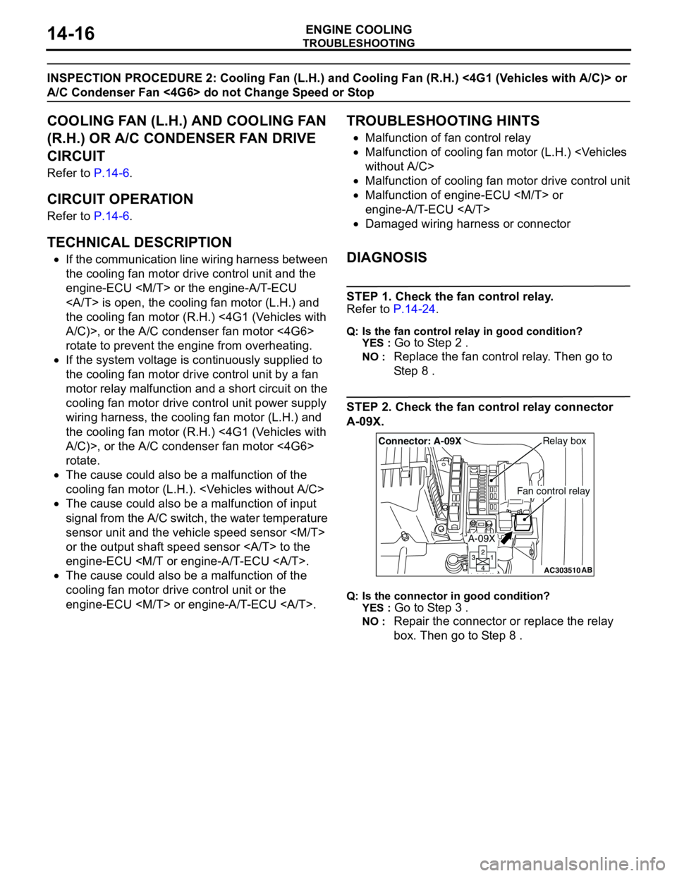
STEP 2. Check the fan control relay connector
A-09X.
Q: Is the connector in good condition?
YES :
Go to Step 3 .
NO : Repair the connector or replace the relay
box. Then go to Step 8 .
AC303510AB
Fan control relay
Relay boxConnector: A-09X
A-09X
Page 41 of 788
THERMOSTAT
ENGINE COOLING14-27
REMOVAL SERVICE POINT
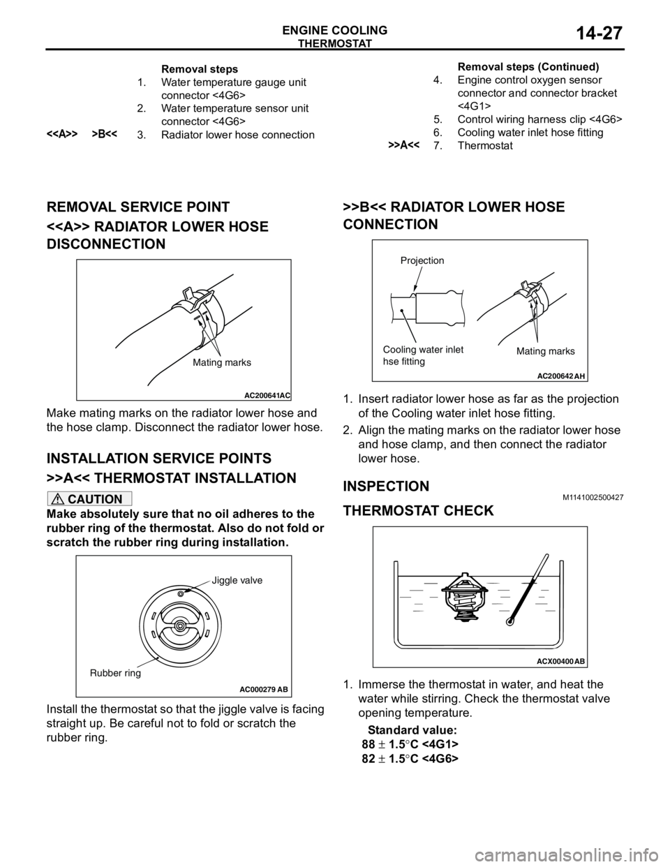
<> RADIATOR LOWER HOSE
DISCONNECTION
Make mating marks on the radiator lower hose and
the hose clamp. Disconnect the radiator lower hose.
INSTALLATION SERVICE POINTS
>>A<< THERMOSTAT INSTALLATION
CAUTION
Make absolutely sure that no oil adheres to the
rubber ring of the thermostat. Also do not fold or
scratch the rubber ring during installation.
Install the thermostat so that the jiggle valve is facing
straight up. Be careful not to fold or scratch the
rubber ring.
>>B<< RADIATOR LOWER HOSE
CONNECTION
1. Insert radiator lower hose as far as the projection
of the Cooling water inlet hose fitting.
2. Align the mating marks on the radiator lower hose
and hose clamp, and then connect the radiator
lower hose.
INSPECTIONM1141002500427
THERMOSTAT CHECK
1. Immerse the thermostat in water, and heat the
water while stirring. Check the thermostat valve
opening temperature.
Standard value:
88 ± 1.5°C <4G1>
82 ± 1.5°C <4G6>
Removal steps
1. Water temperature gauge unit
connector <4G6>
2. Water temperature sensor unit
connector <4G6>
<> >B<<3. Radiator lower hose connection4. Engine control oxygen sensor
connector and connector bracket
<4G1>
5. Control wiring harness clip <4G6>
6. Cooling water inlet hose fitting>>A<<7. ThermostatRemoval steps (Continued)
AC200641AC
Mating marks
AC000279
Jiggle valve
Rubber ring
AB
AC200642
Mating marks
Projection
Cooling water inlet
hse fitting
AH
ACX00400
AB
Page 45 of 788
WATER HOSE AND WATER PIPE
ENGINE COOLING14-31
WATER HOSE AND WATER PIPE
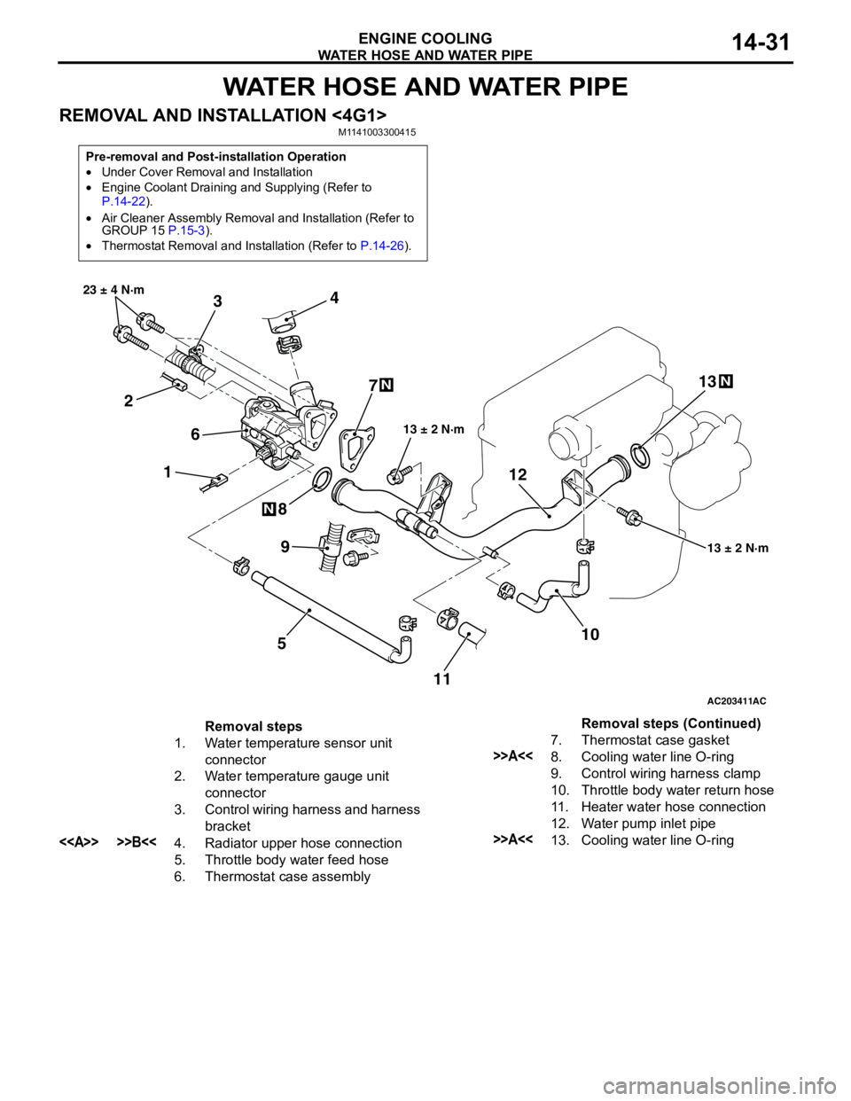
REMOVAL AND INSTALLATION <4G1>M1141003300415
Pre-removal and Post-installation Operation
•Under Cover Removal and Installation
•Engine Coolant Draining and Supplying (Refer to
P.14-22).
•Air Cleaner Assembly Removal and Installation (Refer to
GROUP 15 P.15-3).
•Thermostat Removal and Installation (Refer to P.14-26).
AC203411
1 234
5 67
8
10 9
13 ± 2 N·m 23 ± 4 N·m
13 ± 2 N·m
N
N
AC
111213
N
Removal steps
1. Water temperature sensor unit
connector
2. Water temperature gauge unit
connector
3. Control wiring harness and harness
bracket
<> >>B<<4. Radiator upper hose connection
5. Throttle body water feed hose
6. Thermostat case assembly7. Thermostat case gasket
>>A<<8. Cooling water line O-ring
9. Control wiring harness clamp
10. Throttle body water return hose
11. Heater water hose connection
12. Water pump inlet pipe
>>A<<13. Cooling water line O-ringRemoval steps (Continued)
Page 592 of 788
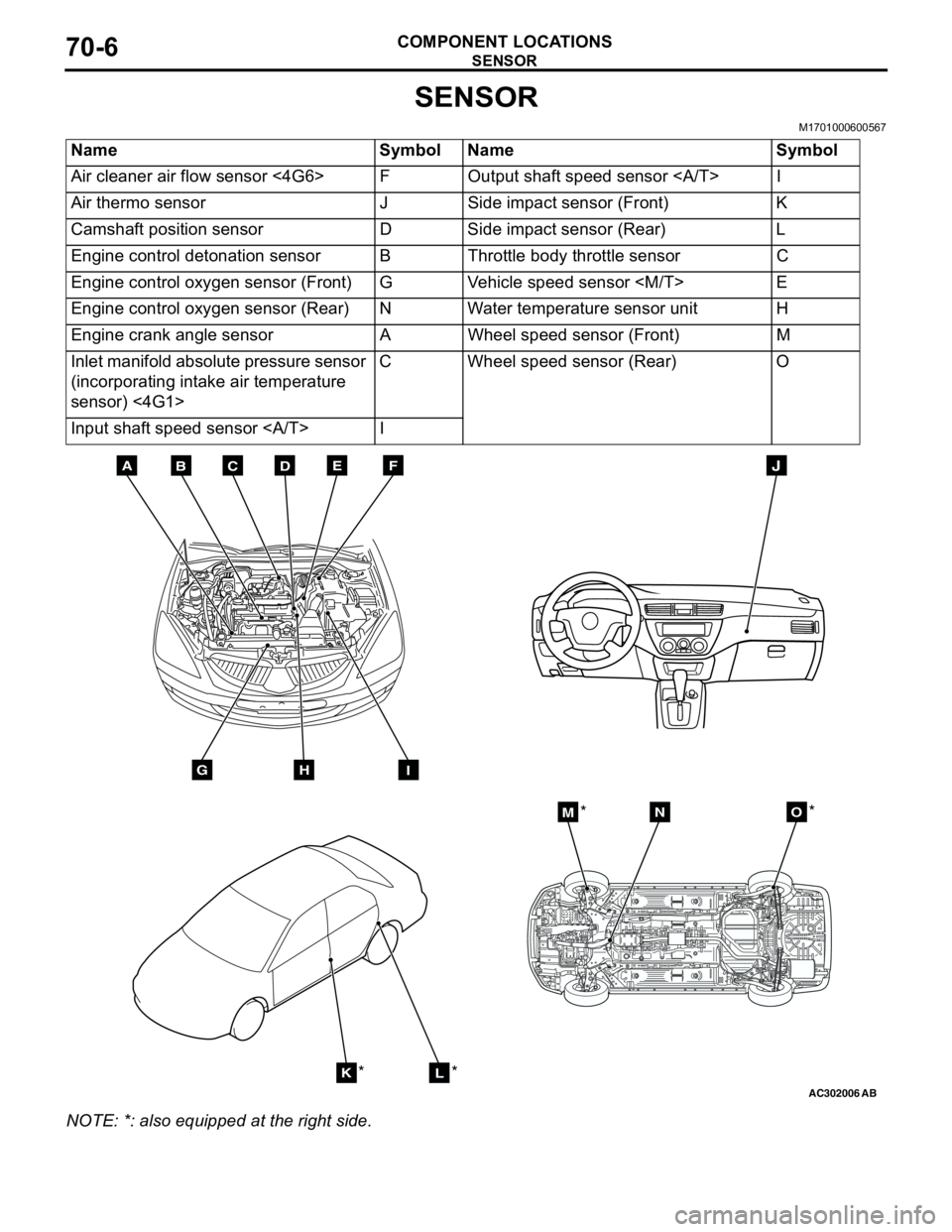
SENSOR
COMPONENT LOCATIONS70-6
SENSOR
M1701000600567
NOTE: *: also equipped at the right side.Name Symbol Name Symbol
Air cleaner air flow sensor <4G6> F Output shaft speed sensor I
Air thermo sensor J Side impact sensor (Front) K
Camshaft position sensor D Side impact sensor (Rear) L
Engine control detonation sensor B Throttle body throttle sensor C
Engine control oxygen sensor (Front) G Vehicle speed sensor
Engine control oxygen sensor (Rear) N Water temperature sensor unit H
Engine crank angle sensor A Wheel speed sensor (Front) M
Inlet manifold absolute pressure sensor
(incorporating intake air temperature
sensor) <4G1>C Wheel speed sensor (Rear) O
Input shaft speed sensor I
AC302006AB
BDCFEA
GHI
J
KL
MNO
*
***
Page 594 of 788
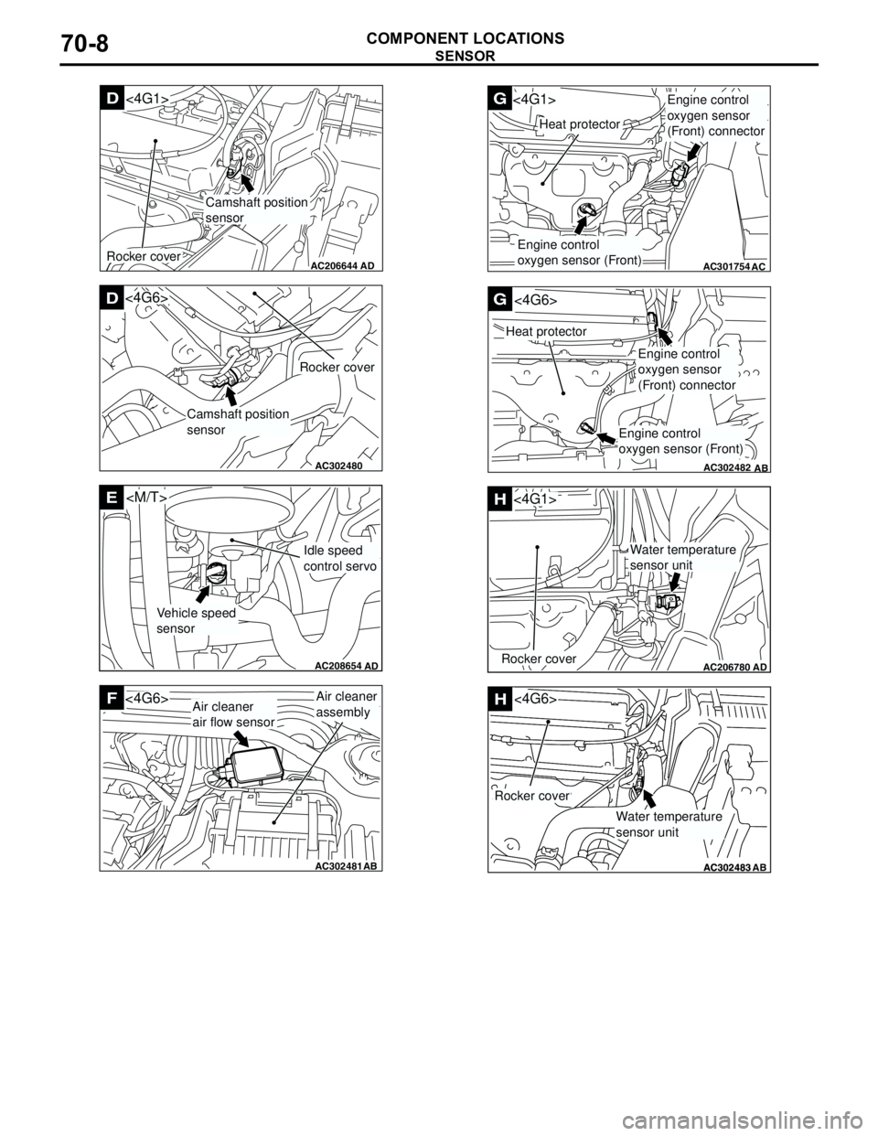
SENSOR
COMPONENT LOCATIONS70-8
AC206644
AD
Camshaft position
sensor
D<4G1>
Rocker cover
AC302480AB
D
Camshaft position
sensor
Rocker cover
<4G6>
AC208654
AD
E
Vehicle speed
sensor
Idle speed
control servo
AC302481AB
FAir cleaner
assembly<4G6>Air cleaner
air flow sensor
AB
AC301754
G<4G1>
AC
Heat protector
Engine control
oxygen sensor (Front)
Engine control
oxygen sensor
(Front) connector
AC302482
G
AB
Heat protector
<4G6>
Engine control
oxygen sensor
(Front) connector
Engine control
oxygen sensor (Front)
AC206780AD
H
Rocker cover
<4G1>
Water temperature
sensor unit
AC302483AC302483
<4G6>H
AB
Rocker cover
Water temperature
sensor unit
Page 615 of 788
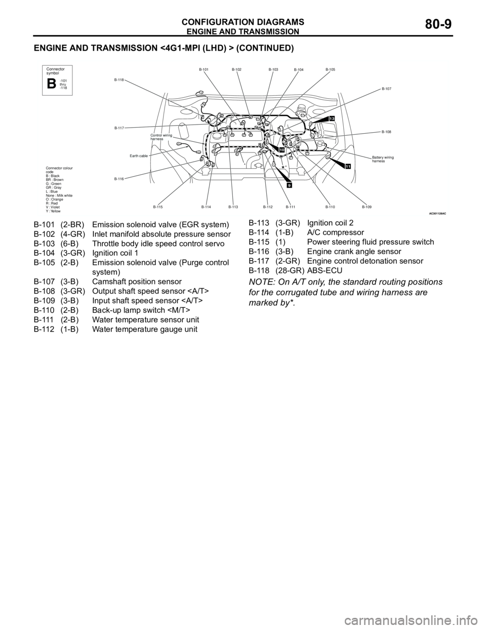
ENGINE AND TRANSMISSION
CONFIGURATION DIAGRAMS80-9
ENGINE AND TRANSMISSION <4G1-MPI (LHD) > (CONTINUED)
NOTE: On A/T only, the standard routing positions
for the corrugated tube and wiring harness are
marked by*.
AC301128
B-118B-101 B-102
B-113
B-114 B-115 B-116B-117
Earth cable
Control wiring
harness
Connector colour
code
B : Black
BR : Brown
G : Green
GR : Gray
L : Blue
None : Milk white
O : Orange
R : Red
V : Violet
Y : Yellow
Connector
symbol
-101
thru
-118B
*
AC
9
10
11
13
B-103
B-104B-105
B-107
B-108
Battery wiring
harness
B-109
B-110 B-111
*
B-112
B-101 (2-BR) Emission solenoid valve (EGR system)
B-102 (4-GR) Inlet manifold absolute pressure sensor
B-103 (6-B) Throttle body idle speed control servo
B-104 (3-GR) Ignition coil 1
B-105 (2-B) Emission solenoid valve (Purge control
system)
B-107 (3-B) Camshaft position sensor
B-108 (3-GR) Output shaft speed sensor
B-109 (3-B) Input shaft speed sensor
B-110 (2-B) Back-up lamp switch
B-111 (2-B) Water temperature sensor unit
B-112 (1-B) Water temperature gauge unitB-113 (3-GR) Ignition coil 2
B-114 (1-B) A/C compressor
B-115 (1) Power steering fluid pressure switch
B-116 (3-B) Engine crank angle sensor
B-117 (2-GR) Engine control detonation sensor
B-118 (28-GR) ABS-ECU
Page 617 of 788

ENGINE AND TRANSMISSION
CONFIGURATION DIAGRAMS80-11
ENGINE AND TRANSMISSION <4G1-MPI (RHD) > (CONTINUED)
NOTE: On A/T only, the standard routing positions
for the corrugated tube and wiring harness are
marked by*.
AC301131
B-117B-101 B-102
B-113 B-114 B-115 B-116
Earth cable
Control wiring
harness
Connector colour
code
B : Black
BR : Brown
G : Green
GR : Gray
L : Blue
None : Milk white
O : Orange
R : Red
V : Violet
Y : Yellow
Connector
symbol
-101
thru
-118B
*
AC
9
10
11
13
B-103
B-104B-105
B-107
B-108
Battery wiring
harness
B-109 B-110 B-111
*
B-112
B-118
B-101 (2-BR) Emission solenoid valve (EGR system)
B-102 (4-GR) Inlet manifold absolute pressure sensor
B-103 (6-B) Throttle body idle speed control servo
B-104 (3-GR) Ignition coil 1
B-105 (2-B) Emission solenoid valve (Purge control
system)
B-107 (3-B) Camshaft position sensor
B-108 (3-GR) Output shaft speed sensor
B-109 (3-B) Input shaft speed sensor
B-110 (2-B) Back-up lamp switch
B-111 (2-B) Water temperature sensor unit
B-112 (1-B) Water temperature gauge unitB-113 (3-GR) Ignition coil 2
B-114 (1-B) A/C compressor
B-115 (1) Power steering fluid pressure switch
B-116 (3-B) Engine crank angle sensor
B-117 (2-GR) Engine control detonation sensor
B-118 (28-GR) ABS-ECU
Page 619 of 788
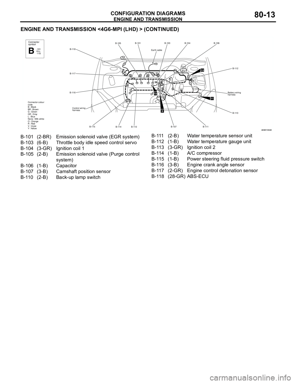
ENGINE AND TRANSMISSION
CONFIGURATION DIAGRAMS80-13
ENGINE AND TRANSMISSION <4G6-MPI (LHD) > (CONTINUED)
AC301134
B-118B-101
B-114 B-115 B-116B-117
Control wiring
harness Connector colour
code
B : Black
BR : Brown
G : Green
GR : Gray
L : Blue
None : Milk white
O : Orange
R : Red
V : Violet
Y : Yellow
B-113
B-105Connector
symbol
-101
thru
-118B
AC
9
10
11
13
B-103B-104B-106
B-112
B-110 Battery wiring
harness
B-111
B-107
Earth cable
B-101 (2-BR) Emission solenoid valve (EGR system)
B-103 (6-B) Throttle body idle speed control servo
B-104 (3-GR) Ignition coil 1
B-105 (2-B) Emission solenoid valve (Purge control
system)
B-106 (1-B) Capacitor
B-107 (3-B) Camshaft position sensor
B-110 (2-B) Back-up lamp switch B-111 (2-B) Water temperature sensor unit
B-112 (1-B) Water temperature gauge unit
B-113 (3-GR) Ignition coil 2
B-114 (1-B) A/C compressor
B-115 (1-B) Power steering fluid pressure switch
B-116 (3-B) Engine crank angle sensor
B-117 (2-GR) Engine control detonation sensor
B-118 (28-GR) ABS-ECU
Page 621 of 788
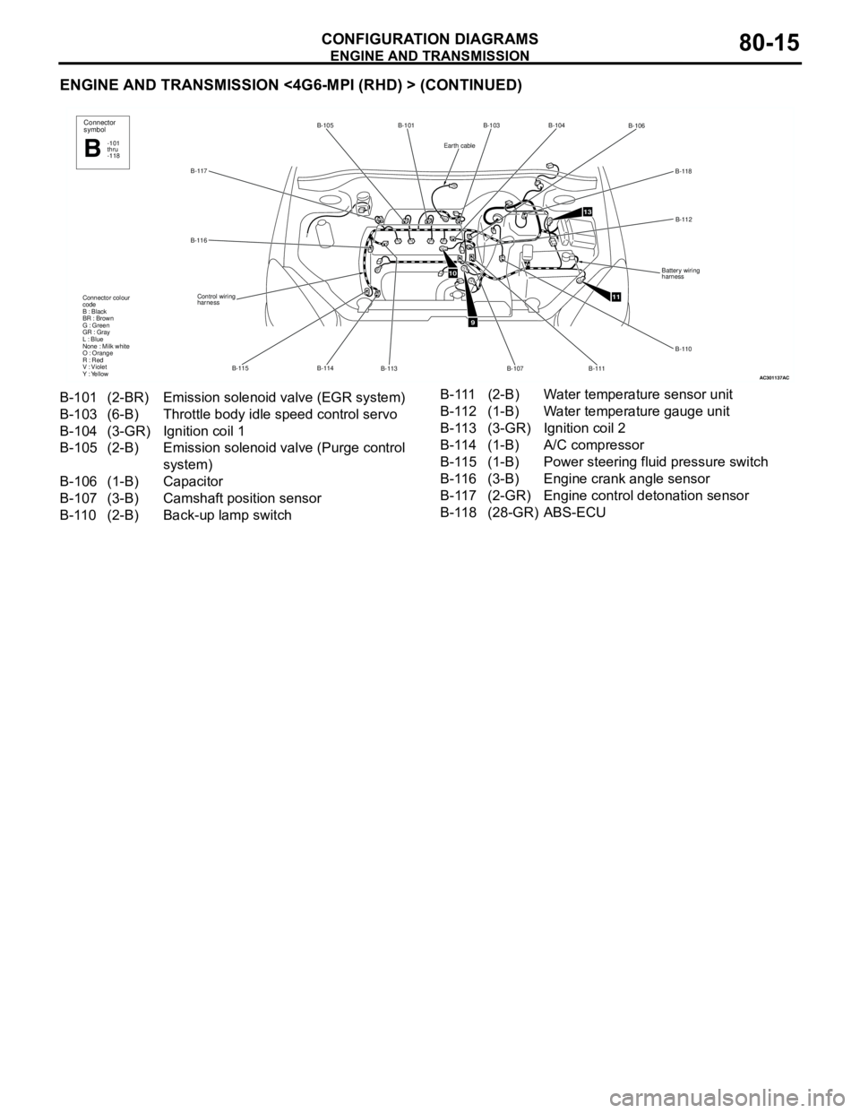
ENGINE AND TRANSMISSION
CONFIGURATION DIAGRAMS80-15
ENGINE AND TRANSMISSION <4G6-MPI (RHD) > (CONTINUED)
AC301137
B-117B-105 B-101
B-113 B-114 B-115 B-116
Control wiring
harness Connector colour
code
B : Black
BR : Brown
G : Green
GR : Gray
L : Blue
None : Milk white
O : Orange
R : Red
V : Violet
Y : Yellow
Connector
symbol
-101
thru
-118B
AC
9
11
13
B-103
B-106
B-118
B-112
Battery wiring
harness
B-110
B-111
B-107
B-104
10
Earth cable
B-101 (2-BR) Emission solenoid valve (EGR system)
B-103 (6-B) Throttle body idle speed control servo
B-104 (3-GR) Ignition coil 1
B-105 (2-B) Emission solenoid valve (Purge control
system)
B-106 (1-B) Capacitor
B-107 (3-B) Camshaft position sensor
B-110 (2-B) Back-up lamp switch B-111 (2-B) Water temperature sensor unit
B-112 (1-B) Water temperature gauge unit
B-113 (3-GR) Ignition coil 2
B-114 (1-B) A/C compressor
B-115 (1-B) Power steering fluid pressure switch
B-116 (3-B) Engine crank angle sensor
B-117 (2-GR) Engine control detonation sensor
B-118 (28-GR) ABS-ECU