ABS MITSUBISHI LANCER 2005 Workshop Manual
[x] Cancel search | Manufacturer: MITSUBISHI, Model Year: 2005, Model line: LANCER, Model: MITSUBISHI LANCER 2005Pages: 788, PDF Size: 45.98 MB
Page 16 of 788
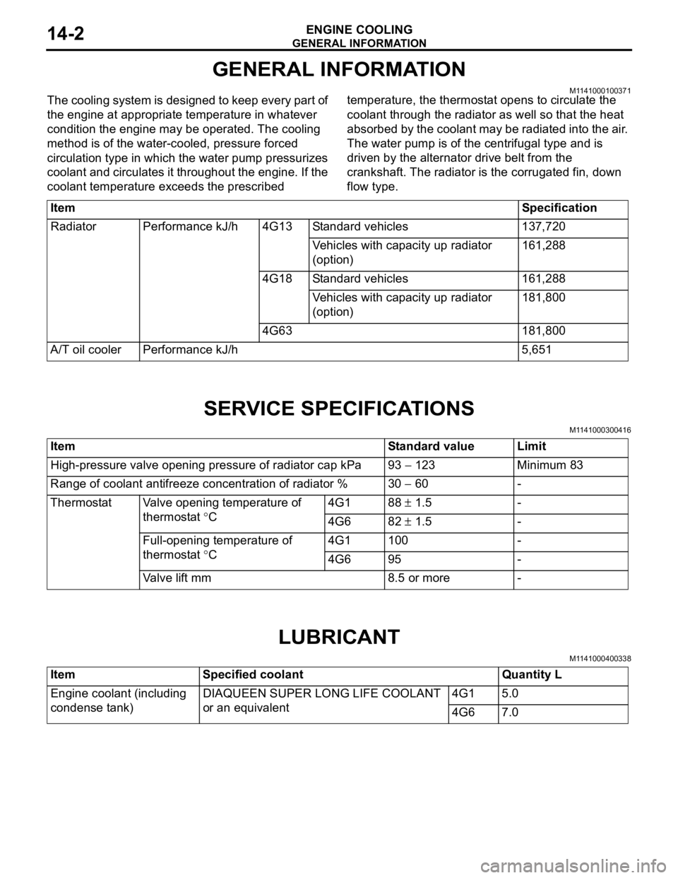
GENERAL INFORMATION
ENGINE COOLING14-2
GENERAL INFORMATION
M1141000100371The cooling system is designed to keep every part of
the engine at appropriate temperature in whatever
condition the engine may be operated. The cooling
method is of the water-cooled, pressure forced
circulation type in which the water pump pressurizes
coolant and circulates it throughout the engine. If the
coolant temperature exceeds the prescribed temperature, the thermostat opens to circulate the
coolant through the radiator as well so that the heat
absorbed by the coolant may be radiated into the air.
The water pump is of the centrifugal type and is
driven by the alternator drive belt from the
crankshaft. The radiator is the corrugated fin, down
flow type.
SERVICE SPECIFICATIONS
M1141000300416
LUBRICANT
M1141000400338
ItemSpecification
Radiator Performance kJ/h 4G13 Standard vehicles 137,720
Vehicles with capacity up radiator
(option)161,288
4G18 Standard vehicles 161,288
Vehicles with capacity up radiator
(option)181,800
4G63 181,800
A/T oil cooler Performance kJ/h 5,651
Item Standard value Limit
High-pressure valve opening pressure of radiator cap kPa 93 − 123 Minimum 83
Range of coolant antifreeze concentration of radiator % 30 − 60 -
Thermostat Valve opening temperature of
thermostat °C4G1 88 ± 1.5 -
4G6 82 ± 1.5 -
Full-opening temperature of
thermostat °C4G1 100 -
4G6 95 -
Valve lift mm 8.5 or more -
Item Specified coolant Quantity L
Engine coolant (including
condense tank)DIAQUEEN SUPER LONG LIFE COOLANT
or an equivalent4G1 5.0
4G6 7.0
Page 41 of 788
THERMOSTAT
ENGINE COOLING14-27
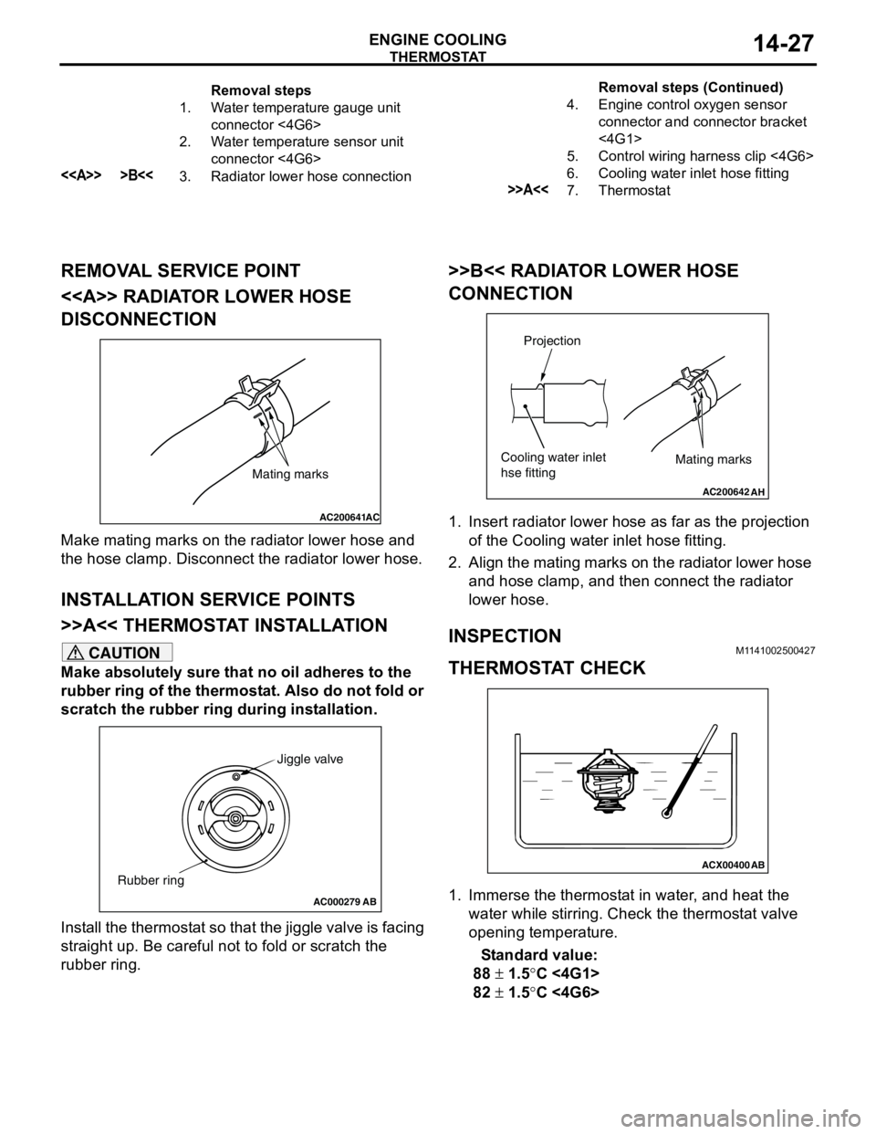
REMOVAL SERVICE POINT
<> RADIATOR LOWER HOSE
DISCONNECTION
Make mating marks on the radiator lower hose and
the hose clamp. Disconnect the radiator lower hose.
INSTALLATION SERVICE POINTS
>>A<< THERMOSTAT INSTALLATION
CAUTION
Make absolutely sure that no oil adheres to the
rubber ring of the thermostat. Also do not fold or
scratch the rubber ring during installation.
Install the thermostat so that the jiggle valve is facing
straight up. Be careful not to fold or scratch the
rubber ring.
>>B<< RADIATOR LOWER HOSE
CONNECTION
1. Insert radiator lower hose as far as the projection
of the Cooling water inlet hose fitting.
2. Align the mating marks on the radiator lower hose
and hose clamp, and then connect the radiator
lower hose.
INSPECTIONM1141002500427
THERMOSTAT CHECK
1. Immerse the thermostat in water, and heat the
water while stirring. Check the thermostat valve
opening temperature.
Standard value:
88 ± 1.5°C <4G1>
82 ± 1.5°C <4G6>
Removal steps
1. Water temperature gauge unit
connector <4G6>
2. Water temperature sensor unit
connector <4G6>
<> >B<<3. Radiator lower hose connection4. Engine control oxygen sensor
connector and connector bracket
<4G1>
5. Control wiring harness clip <4G6>
6. Cooling water inlet hose fitting>>A<<7. ThermostatRemoval steps (Continued)
AC200641AC
Mating marks
AC000279
Jiggle valve
Rubber ring
AB
AC200642
Mating marks
Projection
Cooling water inlet
hse fitting
AH
ACX00400
AB
Page 57 of 788
INLET MANIFOLD
INTAKE AND EXHAUST15-5
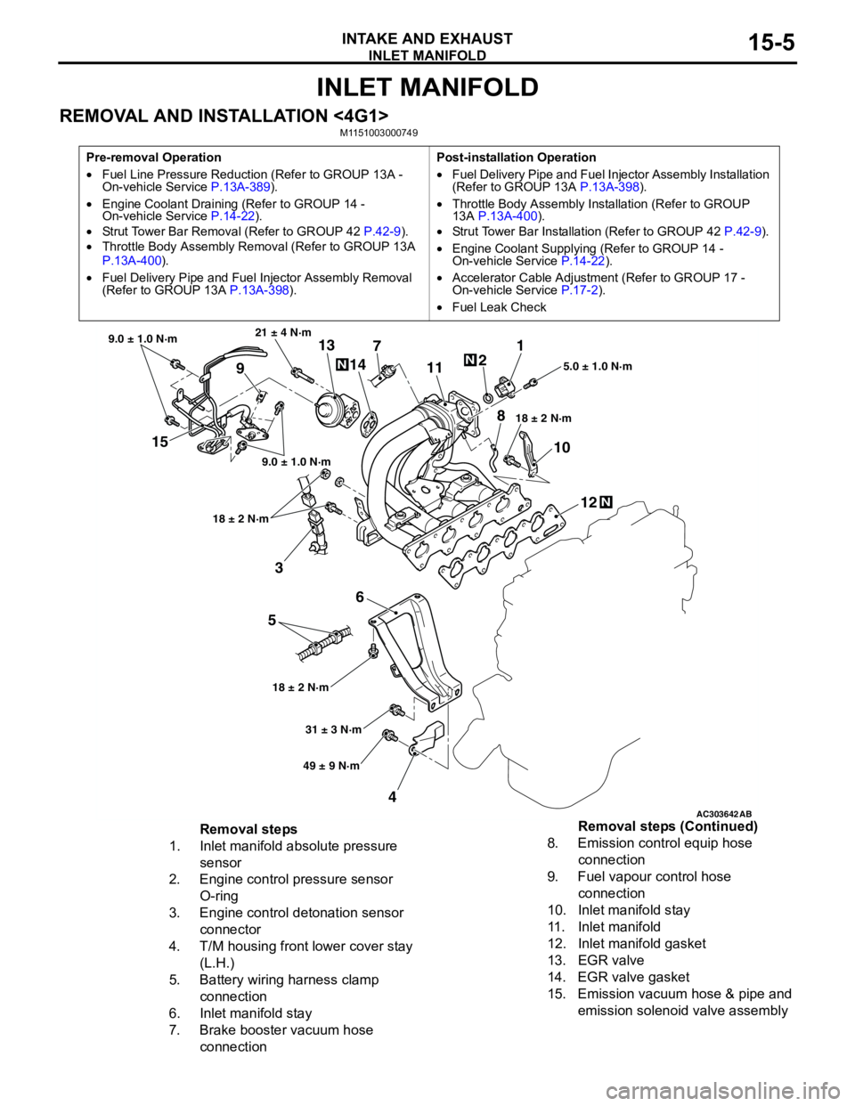
INLET MANIFOLD
REMOVAL AND INSTALLATION <4G1>M1151003000749
Pre-removal Operation
•Fuel Line Pressure Reduction (Refer to GROUP 13A -
On-vehicle Service P.13A-389).
•Engine Coolant Draining (Refer to GROUP 14 -
On-vehicle Service P.14-22).
•Strut Tower Bar Removal (Refer to GROUP 42 P.42-9).
•Throttle Body Assembly Removal (Refer to GROUP 13A
P.13A-400).
•Fuel Delivery Pipe and Fuel Injector Assembly Removal
(Refer to GROUP 13A P.13A-398).Post-installation Operation
•Fuel Delivery Pipe and Fuel Injector Assembly Installation
(Refer to GROUP 13A P.13A-398).
•Throttle Body Assembly Installation (Refer to GROUP
13A P.13A-400).
•Strut Tower Bar Installation (Refer to GROUP 42 P.42-9).
•Engine Coolant Supplying (Refer to GROUP 14 -
On-vehicle Service P.14-22).
•Accelerator Cable Adjustment (Refer to GROUP 17 -
On-vehicle Service P.17-2).
•Fuel Leak Check
AC303642AB
15
3
6
5
412 10 71
2
11
913
14
21 ± 4 N·m
9.0 ± 1.0 N·m
9.0 ± 1.0 N·m
18 ± 2 N·m
18 ± 2 N·m18 ± 2 N·m5.0 ± 1.0 N·m
31 ± 3 N·m
49 ± 9 N·m
N
N
N
8
Removal steps
1. Inlet manifold absolute pressure
sensor
2. Engine control pressure sensor
O-ring
3. Engine control detonation sensor
connector
4. T/M housing front lower cover stay
(L.H.)
5. Battery wiring harness clamp
connection
6. Inlet manifold stay
7. Brake booster vacuum hose
connection8. Emission control equip hose
connection
9. Fuel vapour control hose
connection
10. Inlet manifold stay
11. Inlet manifold
12. Inlet manifold gasket
13. EGR valve
14. EGR valve gasket
15. Emission vacuum hose & pipe and
emission solenoid valve assembly Removal steps (Continued)
Page 118 of 788
EMISSION CONTROL
ENGINE AND EMISSION CONTROL17-10
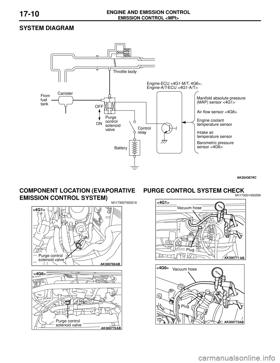
SYSTEM DIAGRAM
COMPONENT LOCATION (EVAPORATIVE
EMISSION CONTROL SYSTEM)
M1173007500216
PURGE CONTROL SYSTEM CHECKM1173001400299
AK204367AC
Throttle body
Canister
From
fuel
tank
OFF
ONPurge
control
solenoid
valveControl
relay
BatteryEngine-ECU <4G1-M/T, 4G6>,
Engine-A/T-ECU <4G1-A/T>
Air flow sensor <4G6>
Engine coolant
temperature sensor
Intake air
temperature sensor
Barometric pressure
sensor <4G6> Manifold absolute pressure
(MAP) sensor <4G1>
AK300769
<4G1>
AB
Purge control
solenoid valve
AK300770
<4G6>
AB
Purge control
solenoid valve
AK300771
<4G1>
AB
Plug
Vacuum hose
AK300772
<4G6>
AB
Plug
Vacuum hose
Page 121 of 788
EMISSION CONTROL
ENGINE AND EMISSION CONTROL17-13
EXHAUST GAS RECIRCULATION
(EGR) SYSTEM
GENERAL INFORMATION (EGR SYSTEM)M1173005200327
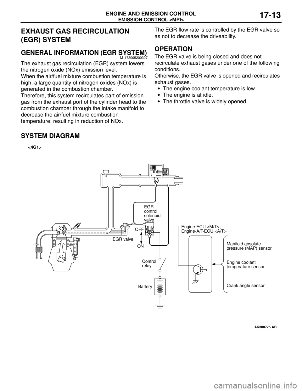
The exhaust gas recirculation (EGR) system lowers
the nitrogen oxide (NOx) emission level.
When the air/fuel mixture combustion temperature is
high, a large quantity of nitrogen oxides (NOx) is
generated in the combustion chamber.
Therefore, this system recirculates part of emission
gas from the exhaust port of the cylinder head to the
combustion chamber through the intake manifold to
decrease the air/fuel mixture combustion
temperature, resulting in reduction of NOx.The EGR flow rate is controlled by the EGR valve so
as not to decrease the driveability.
OPERATION
The EGR valve is being closed and does not
recirculate exhaust gases under one of the following
conditions.
Otherwise, the EGR valve is opened and recirculates
exhaust gases.
•The engine coolant temperature is low.
•The engine is at idle.
•The throttle valve is widely opened.
SYSTEM DIAGRAM
AK300775
Manifold absolute
pressure (MAP) sensor Engine-ECU
Engine-A/T-ECU
Engine coolant
temperature sensor
Crank angle sensor EGR
control
solenoid
valve
EGR valveOFF
ON
Control
relay
Battery
AB
<4G1>
Page 134 of 788
GENERAL INFORMATION
FRONT AXLE26-2
GENERAL INFORMATION
M1261000100347
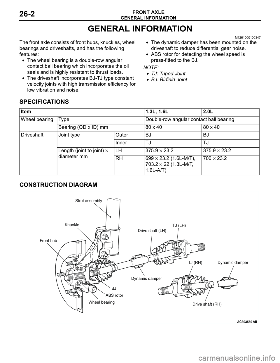
The front axle consists of front hubs, knuckles, wheel
bearings and driveshafts, and has the following
features:
•The wheel bearing is a double-row angular
contact ball bearing which incorporates the oil
seals and is highly resistant to thrust loads.
•The driveshaft incorporates BJ-TJ type constant
velocity joints with high transmission efficiency for
low vibration and noise.•The dynamic damper has been mounted on the
driveshaft to reduce differential gear noise.
•ABS rotor for detecting the wheel speed is
press-fitted to the BJ.
NOTE: .
•TJ: Tripod Joint
•BJ: Birfield Joint
SPECIFICATIONS
CONSTRUCTION DIAGRAM
Item 1.3L, 1.6L 2.0L
Wheel bearing Type Double-row angular contact ball bearing
Bearing (OD x ID) mm 80 x 40 80 x 40
Driveshaft Joint type Outer BJ BJ
Inner TJ TJ
Length (joint to joint) ×
diameter mm LH 375.9 × 23.2 375.9 × 23.2
RH 699 × 23.2 (1.6L-M/T),
703.2 × 22 (1.3L-M/T,
1.6L-A/T)700 × 23.2
AC303569
Front hubKnuckleStrut assembly
TJ (LH)
Drive shaft (LH)
Dynamic damper
BJ
Wheel bearing
Drive shaft (RH) TJ (RH)
AB
ABS rotorDynamic damper
Page 140 of 788
FRONT AXLE HUB ASSEMBLY
FRONT AXLE26-8
FRONT AXLE HUB ASSEMBLY
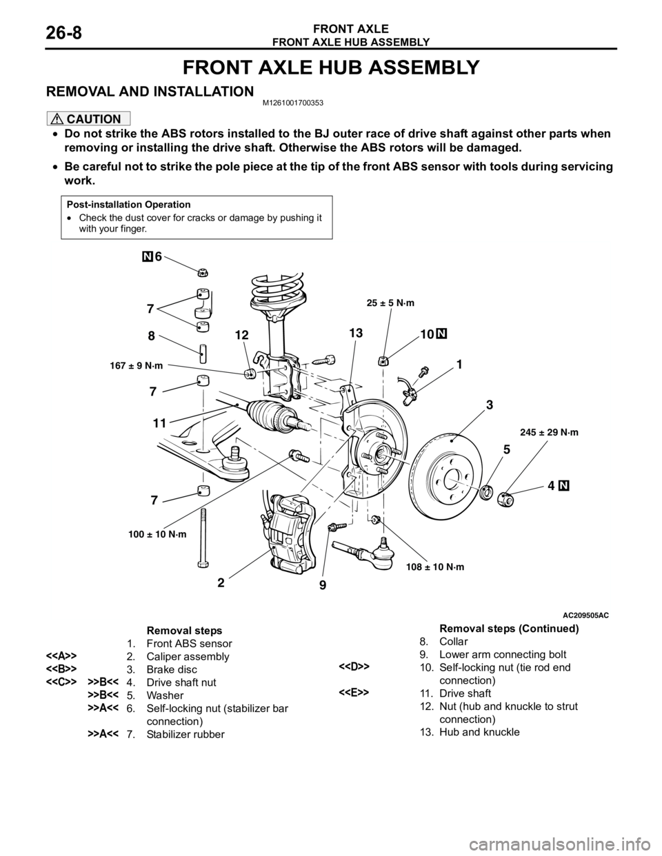
REMOVAL AND INSTALLATIONM1261001700353
CAUTION
•Do not strike the ABS rotors installed to the BJ outer race of drive shaft against other parts when
removing or installing the drive shaft. Otherwise the ABS rotors will be damaged.
•Be careful not to strike the pole piece at the tip of the front ABS sensor with tools during servicing
work.
Post-installation Operation
•Check the dust cover for cracks or damage by pushing it
with your finger.
AC209505
N
N
N
5
4 3 1 810
9 2 76
167 ± 9 N·m25 ± 5 N·m
108 ± 10 N·m245 ± 29 N·m
100 ± 10 N·m
AC
7
7
111213
Removal steps
1. Front ABS sensor
<>
2. Caliper assembly
<>
3. Brake disc
<
>>B<<5. Washer
>>A<<6. Self-locking nut (stabilizer bar
connection)
>>A<<7. Stabilizer rubber8. Collar
9. Lower arm connecting bolt
<
10. Self-locking nut (tie rod end
connection)
<
11 . D r i v e s h a f t
12. Nut (hub and knuckle to strut
connection)
13. Hub and knuckle
Removal steps (Continued)
Page 144 of 788
Page 146 of 788
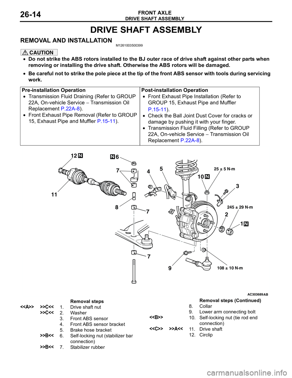
DRIVE SHAFT ASSEMBLY
FRONT AXLE26-14
DRIVE SHAFT ASSEMBLY
REMOVAL AND INSTALLATIONM1261003500399
CAUTION
•Do not strike the ABS rotors installed to the BJ outer race of drive shaft against other parts when
removing or installing the drive shaft. Otherwise the ABS rotors will be damaged.
•Be careful not to strike the pole piece at the tip of the front ABS sensor with tools during servicing
work.
Pre-installation Operation
•Transmission Fluid Draining (Refer to GROUP
22A, On-vehicle Service − Transmission Oil
Replacement P.22A-8).
•Front Exhaust Pipe Removal (Refer to GROUP
15, Exhaust Pipe and Muffler P.15-11).Post-installation Operation
•Front Exhaust Pipe Installation (Refer to
GROUP 15, Exhaust Pipe and Muffler
P.15-11).
•Check the Ball Joint Dust Cover for cracks or
damage by pushing it with your finger.
•Transmission Fluid Filling (Refer to GROUP
22A, On-vehicle Service − Transmission Oil
Replacement P.22A-8).
AC303689AB
9
N
N
NN
10 7
4
3
2
1
25 ± 5 N·m
245 ± 29 N·m
108 ± 10 N·m
8
5 6
1112
7
7
Removal steps
<> >>C<<1. Drive shaft nut
>>C<<2. Washer
3. Front ABS sensor
4. Front ABS sensor bracket
5. Brake hose bracket
>>B<<6. Self-locking nut (stabilizer bar
connection)
>>B<<7. Stabilizer rubber8. Collar
9. Lower arm connecting bolt
<>10. Self-locking nut (tie rod end
connection)
<
12. CirclipRemoval steps (Continued)
Page 150 of 788
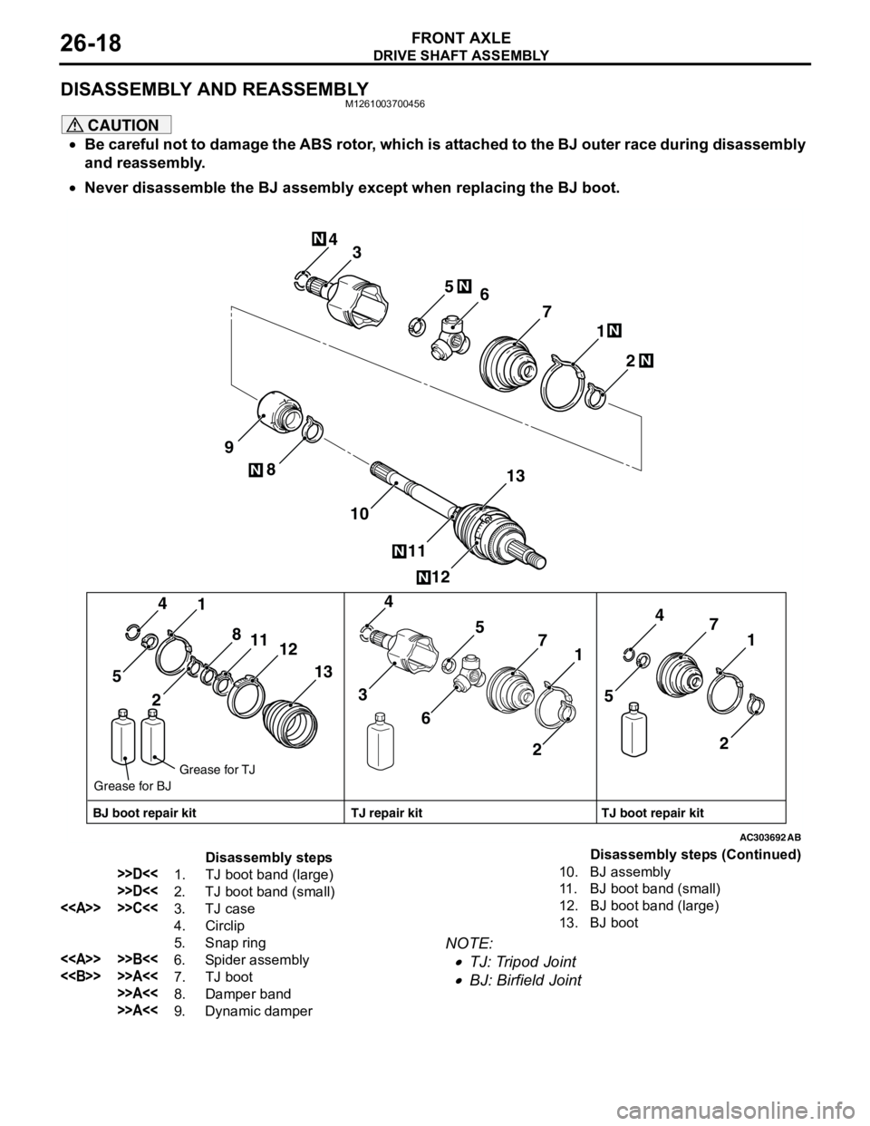
DRIVE SHAFT ASSEMBLY
FRONT AXLE26-18
DISASSEMBLY AND REASSEMBLYM1261003700456
CAUTION
•Be careful not to damage the ABS rotor, which is attached to the BJ outer race during disassembly
and reassembly.
•Never disassemble the BJ assembly except when replacing the BJ boot.
NOTE: .
•TJ: Tripod Joint
•BJ: Birfield Joint
AC303692
2 1 4
12 8
11 10 97
13 6 5N
N
N
3
N
N
21 4
13 8
11
12
5
21 4
7
65
3
21 4
7
5
AB
N
N
BJ boot repair kitTJ boot repair kit TJ repair kit Grease for TJ
Grease for BJ
Disassembly steps
>>D<<1. TJ boot band (large)
>>D<<2. TJ boot band (small)
<> >>C<<3. TJ case
4. Circlip
5. Snap ring
<> >>B<<6. Spider assembly
<> >>A<<7. TJ boot
>>A<<8. Damper band
>>A<<9. Dynamic damper10. BJ assembly
11. BJ boot band (small)
12. BJ boot band (large)
13. BJ bootDisassembly steps (Continued)