Special tool MITSUBISHI LANCER 2006 Repair Manual
[x] Cancel search | Manufacturer: MITSUBISHI, Model Year: 2006, Model line: LANCER, Model: MITSUBISHI LANCER 2006Pages: 800, PDF Size: 45.03 MB
Page 238 of 800
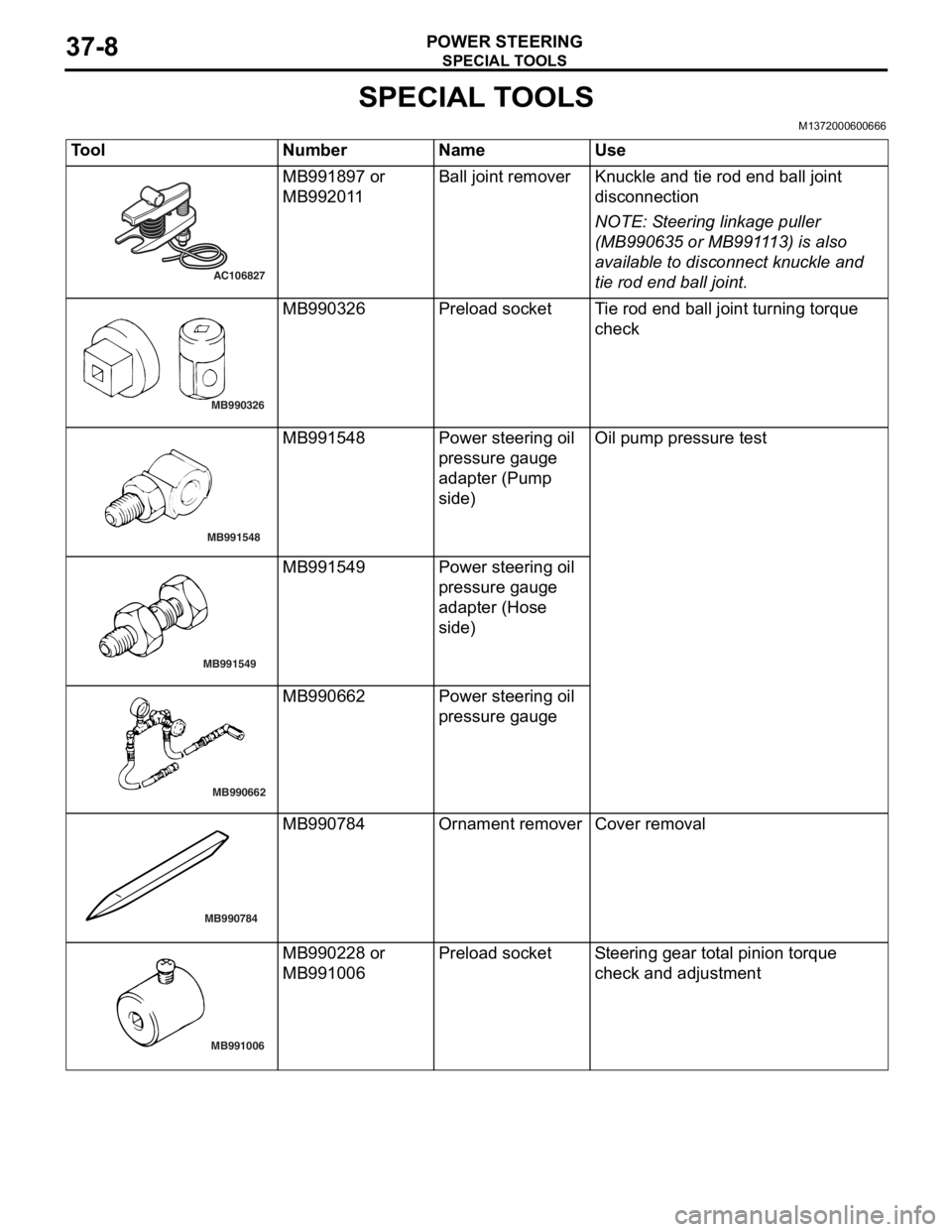
SPECIAL TOOLS
POWER STEERING37-8
SPECIAL TOOLS
M1372000600666
ToolNumberNameUse
AC106827
MB991897 or
MB9920
1 1Ball j o in t remo verKnuckle and tie rod e nd ball joint
discon
nection
NOTE: St eering linkage pu lle r
(MB990 635 o r MB991 1 13) is also
ava
ilab
l e to disconn ect knuckle and
tie ro
d end ball joint.
MB990326
MB9903 26Prel oad socketTi e rod end b a ll join t turning torq ue
che
c k
MB991548
MB9915 48Powe r stee ring oil
pressure g
auge
adapte
r (Pump
sid
e )Oil pump pre ssu re test
MB991549
MB991549Powe r stee ring oil
pressure g
auge
adapte
r (Hose
sid
e )
MB990662
MB9906 62Powe r stee ring oil
pressure g
auge
MB990784
MB990784Ornament removerCover removal
MB991006
MB9902 28 or
MB9910
06Prel oad socketSt e e ring gear to t a l pinion torque
che
ck and ad justmen t
Page 239 of 800
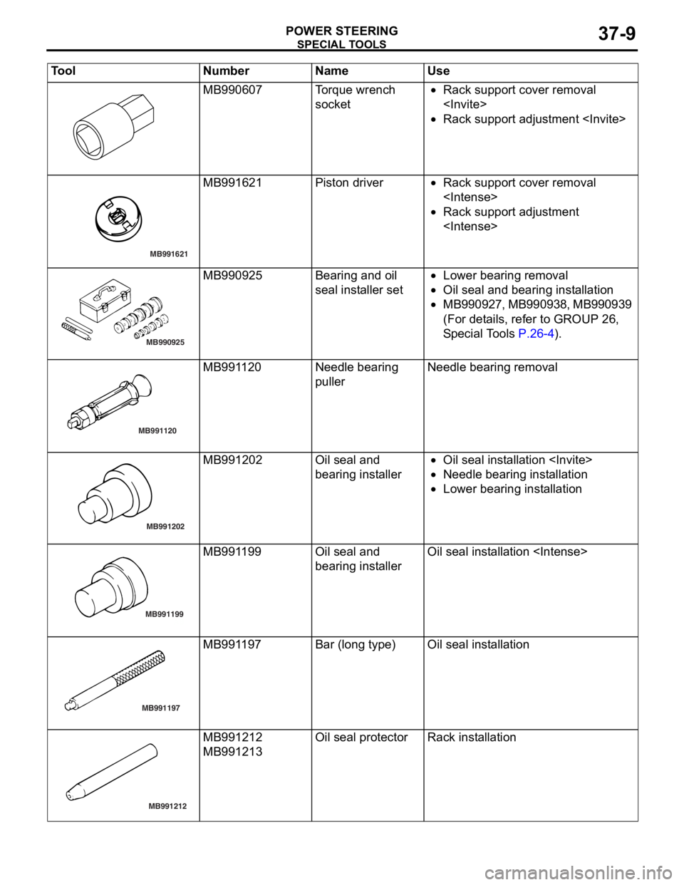
SPECIAL TOOLS
POWER STEERING37-9
MB990607Torque wrench
socket•Rack support cover removal
•Rack support adjustment
MB991621
MB991621Piston driver•Rack suppo rt co ver removal
•Rack support adjustment
MB990925
MB990925Bearing and o il
seal
inst alle r set•Lower bearing re moval
•Oil seal and bearing inst allatio n
•MB 9 9 0 9 2 7 , MB99 09 38, MB9 909 39
(For det
ails, refer to GROUP 26 ,
S
p e c ia l T o ols
P.26-4).
MB991120
MB991120Needle bearing
pullerNeedle bearing remova l
MB991202
MB991202Oil seal an d
bearing in
st aller•Oil seal in st allation
•Need le bearin g inst alla tion
•Lower bearing inst allation
MB991199
AB
MB991199Oil seal an d
bearing in
st allerOil seal inst allatio n
MB991197
MB991197Bar (long type)Oil seal inst allatio n
MB991212
MB991212
MB991213
Oil seal pro t ecto rRack insta llat i on
Tool Num ber Na me Use
Page 242 of 800
ON-VEHICLE SERVICE
POWER STEERING37-12
TIE ROD END BALL JOINT TURNING
TORQUE CHECK
M1372001500554
CAUTION
•Do not remove the tie rod end nut from the
ball joint. Loosen it and use special tool to
avoid possible damage to the ball joint
threads.
•
AC208247AJ
CordBoltMB991897
or
MB992011
Nut
Ball joint
Hang special tool with cord to prevent it from
falling.
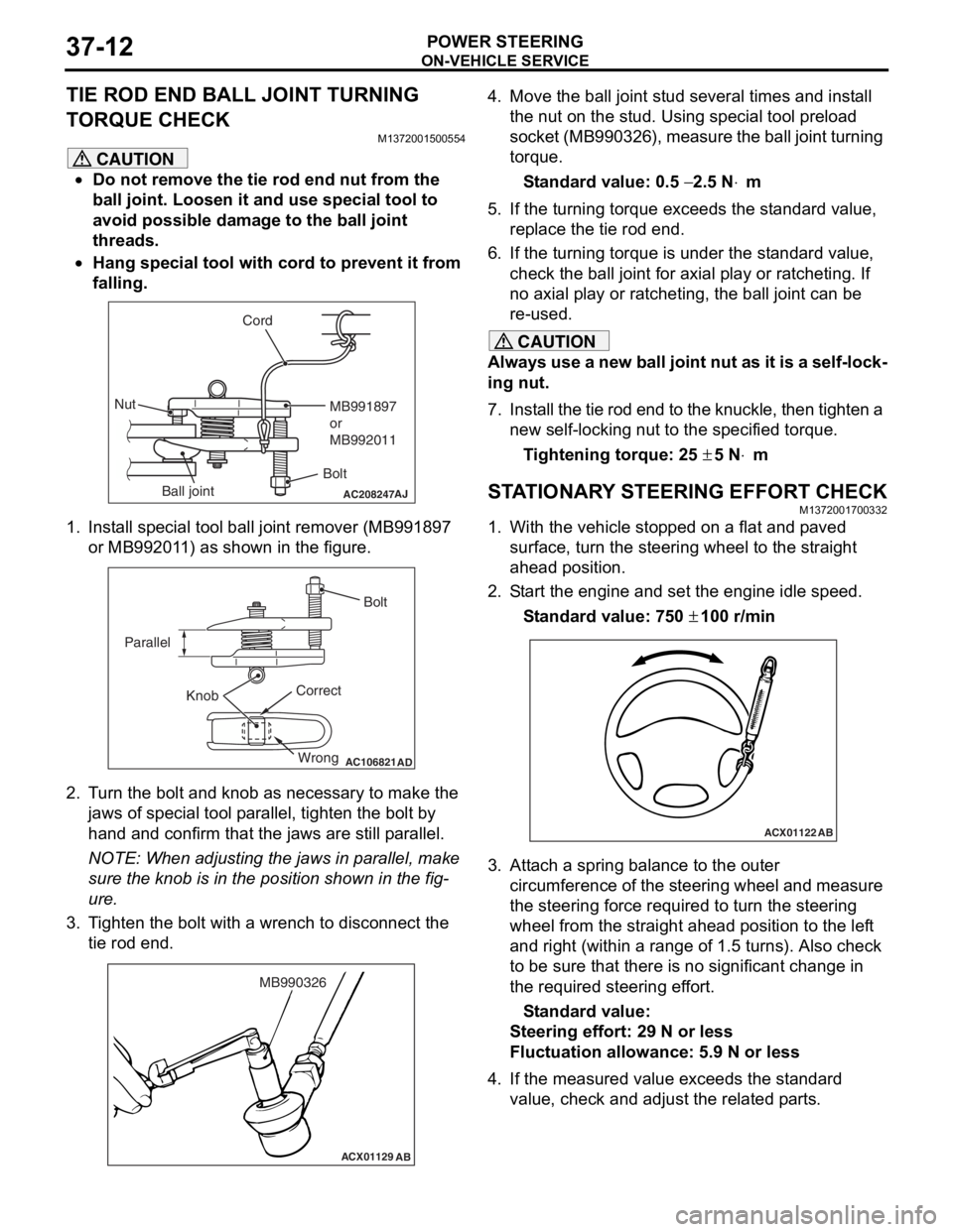
1. Install special tool ball joint remover (MB991897 or MB992011) as shown in the figure.
AC106821
Knob
Parallel
Bolt
Correct Wrong
AD
2. Turn the bolt and knob as necessary to make the jaws of special tool parallel, tighten the bolt by
hand and confirm that the jaws are still parallel.
NOTE: When adjusting the jaws in parallel, make
sure the knob is in the position shown in the fig
-
ure.
3. Tighten the bolt with a wrench to disconnect the tie rod end.
ACX01129 AB
MB990326
4. Move the ball joint stud several times and install
the nut on the stud. Using special tool preload
socket (MB990326), measure the ball joint turning
torque.
Standard value: 0.5 − 2.5 N⋅m
5. If the turning torque exceeds the standard value, replace the tie rod end.
6. If the turning torque is under the standard value, check the ball joint for axial play or ratcheting. If
no axial play or ratcheting, the ball joint can be
re-used.
CAUTION
Always use a new ball joint nut as it is a self-lock-
ing nut.
7. Install the tie rod end to the knuckle, then tighten a new self-locking nut to the specified torque.
Tightening torque: 25 ± 5 N⋅m
STATIONARY STEERING EFFORT CHECKM1372001700332
1. With the vehicle stopped on a flat and paved
surface, turn the steering wheel to the straight
ahead position.
2. Start the engine and set the engine idle speed.
Standard value: 750 ± 100 r/min
ACX01122 AB
3. Attach a spring balance to the outer
circumference of the steering wheel and measure
the steering force required to turn the steering
wheel from the straight ahead position to the left
and right (within a range of 1.5 turns). Also check
to be sure that there is no significant change in
the required steering effort.
Standard value:
Steering effort: 29 N or less
Fluctuation allowance: 5.9 N or less
4. If the measured value exceeds the standard value, check and adjust the related parts.
Page 244 of 800
ON-VEHICLE SERVICE
POWER STEERING37-14
POWER STEERING SYSTEM AIR
BLEEDING
M1372002200330
Perform air bleeding procedure as necessary after
replacing the steering gear or the steering fluid lines.
1. Raise and support the front wheels.
2. Disconnect the ignition coil connectors (Refer to GROUP 16, Ignition Coil
P.16-38 or P.16-39).
CAUTION
Perform air bleeding only while cranking the
engine. If air bleeding is performed while the
engine is running, air could enter the fluid. Dur
-
ing air bleeding, refill the steering fluid supply so
that the level never falls below the "MIN" mark on
the oil reservoir.
3. Turn the steering wheel all the way to the left and
right five or six times wh ile using the starter motor
to crank the engine intermittently several times
(for 15 to 20 seconds).
4. Connect the ignition coil connectors (Refer to GROUP 16, Ignition Coil
P.16-38 or P.16-39).
5. Start the engine (idling).
6. Turn the steering wheel to the left and right until there are no air bubbles in the oil reservoir.
7. Confirm that the fluid is not milky, and that the level is between "MAX" and "MIN" marks.
8. Confirm that there is very little change in the fluid
level when the steering wheel is turned left and
right.
CAUTION
If the fluid level rises suddenly after the engine is
stopped, the air has not been completely bled. If
air bleeding is not complete, there will be abnor
-
mal noises from the pump and the flow-control
valve, and this condition could cause reduce the
life of the power steering components.
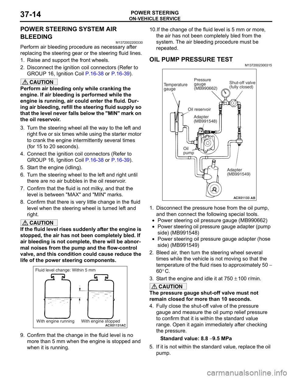
ACX01131With engine running With engine stoppedAC
Fluid level change: Within 5 mm
9. Confirm that the change in the fluid level is no more than 5 mm when the engine is stopped and
when it is running.
10.If the change of the fluid level is 5 mm or more,
the air has not been completely bled from the
system. The air bleeding procedure must be
repeated.
OIL PUMP PRESSURE TEST
M1372002300315
ACX01133
Temperature
gauge
Oil reservoir
Adapter
(MB991548)
Oil
pump Adapter
(MB991549)
AB
Shut-off valve
(fully closed)
Pressure
gauge
(MB990662)
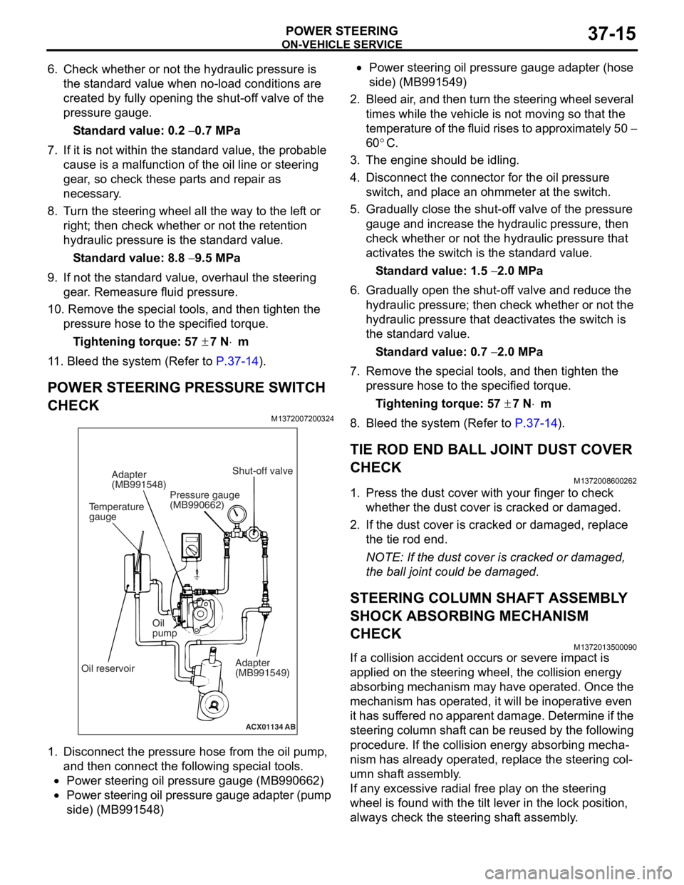
1. Disconnect the pressure hose from the oil pump,
and then connect the following special tools.
•Power steering oil pressure gauge (MB990662)
•Power steering oil pressure gauge adapter (pump
side) (MB991548)
•Power steering oil pressure gauge adapter (hose
side) (MB991549)
2. Bleed air, then turn the steering wheel several times while the vehicle is not moving so that the
temperature of the fluid rises to approximately 50
−
60
°C.
3. Start the engine and idle it at 750 ± 100 r/min.
CAUTION
The pressure gauge shut-off valve must not
remain closed for more than 10 seconds.
4. Fully close the shut-off valve of the pressure gauge and measure the oil pump relief pressure
to confirm that it is within the standard value
range. Open it again immediately after checking
the pressure.
Standard value: 8.8 − 9.5 MPa
5. If it is not within the standard value, replace the oil pump.
Page 245 of 800
ON-VEHICLE SERVICE
POWER STEERING37-15
6. Check whether or not the hydraulic pressure is the standard value when no-load conditions are
created by fully opening the shut-off valve of the
pressure gauge.
Standard value: 0.2 − 0.7 MPa
7. If it is not within the standard value, the probable cause is a malfunction of the oil line or steering
gear, so check these parts and repair as
necessary.
8. Turn the steering wheel all the way to the left or right; then check whether or not the retention
hydraulic pressure is the standard value.
Standard value: 8.8 − 9.5 MPa
9. If not the standard value, overhaul the steering gear. Remeasure fluid pressure.
10. Remove the special tools, and then tighten the
pressure hose to the specified torque.
Tightening torque: 57 ± 7 N⋅m
11. Bleed the system (Refer to P.37-14).
POWER STEERING PRESSURE SWITCH
CHECK
M1372007200324
ACX01134 AB
Temperature
gaugeAdapter
(MB991548)
Oil reservoir Oil
pump
Adapter
(MB991549)
Shut-off valve
Pressure gauge
(MB990662)
1. Disco nnect the pre s sure hose from the oil pump ,
an d then con nect the followin g sp ecial too l s.
•Power steering oil pressure gauge (MB990 662)
•Power steering oil pressure gauge ad apter (pump
side) (MB99154
8)
•Power steering oil pressure gaug e a dapte r (ho s e
side) (MB99154
9)
2. Bleed air , and the n turn t he steering wheel several
times while the vehicle is not moving so that the
tempe r atu r e o f th e flu i d rise s to approximately 50
−
60
°C.
3. Th e engine should be idling.
4.Disco nnect the conne ctor fo r the o il pr essure
switch , and p l ace an o h mmeter a t the switch .
5.Gradua lly close the shut-of f valve of the pressure
g auge a nd in crease the hyd r aulic pre ssu re, the n
check wheth e r or no t the h y drau lic pressure that
a c tivates the switch is the st a ndard valu e.
St andard va lue: 1.5 − 2.0 MPa
6.Gradua lly open the shut-of f va lve and re duce the
h y drau lic p r essure; then check whethe r o r n o t the
h y drau lic pressure that de activate s the switch is
th e st and ard va lue.
St andard va lue: 0.7 − 2.0 MPa
7.Remove the special tools, and then tighten the
p r essure hose to the specified torque .
Ti ghte n ing torque: 57 ± 7 N⋅m
8.Bleed the system (Refer to P.37-14).
TIE ROD END BALL JOINT DUST COVER
CHECK
M13720086 0026 2
1.Press th e dust co ver wit h you r fing er to check
whet her the dust cover is cra cke d or da mage d.
2.If the du st cover is cracked o r damaged, repla c e
th e tie rod end .
NOTE: If the dust cover is cra cke d or da mag ed,
th
e ball jo int could be da mage d.
STEERING COLUMN SHAFT ASSEMBL Y
SHOCK ABSORBING MECHANISM
CHECK
M13720135 0009 0
If a collision accid ent occu rs or seve re imp a ct is
applied on
the steering w heel, the collision energy
abso
r bing mechanism ma y h a ve opera t ed. Once the
mechanism
has o perate d , it will b e ino perative e v en
it has
suf f er ed no app a r en t d a mage . De termin e if the
steering colu
mn shaf t can b e reused b y th e following
proce
dure. If the collision en ergy a b sor b ing mecha
-
nism has already operated, rep l ace the steering col-
umn shaft assembly .
If any excessive radial fre e pla y on the steering
wh
eel is fo und with the tilt lever in the lock po sit i on,
always ch
eck the steering shaf t assembly .
Page 247 of 800
STEERING WHEEL
POWER STEERING37-17
STEERING WHEEL
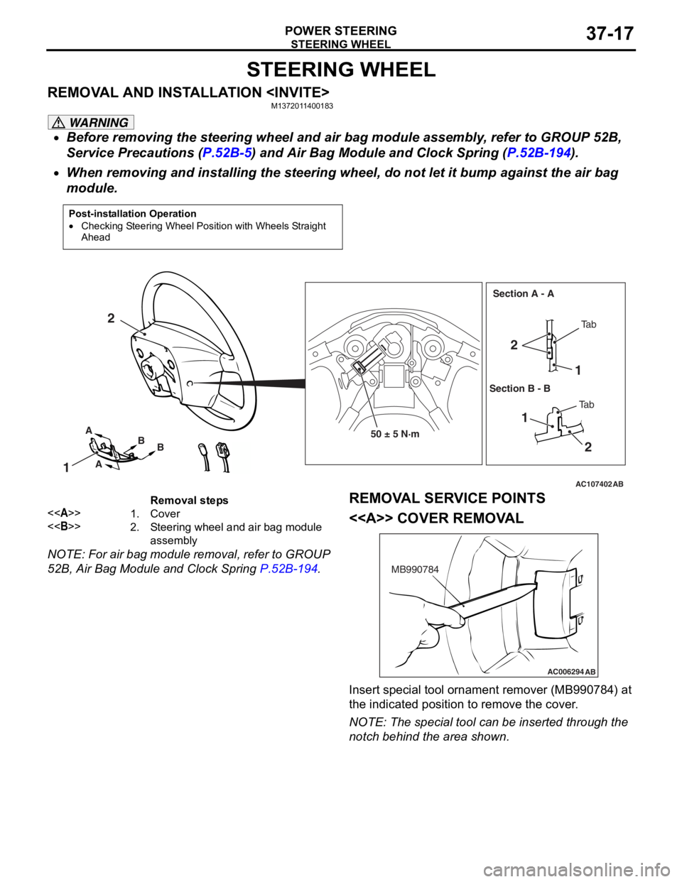
REMOVAL AND INSTALLATION
WARNING
•Before removing the steering wheel and air bag module assembly, refer to GROUP 52B,
Service Precautions (
P.52B-5) and Air Bag Module and Clock Spring (P.52B-194).
•
Post-installation Operation
•Checking Steering Wheel Position with Wheels Straight
Ahead
AC107402AB
50 ± 5 N·m
1
2
21
1 2
A
A B
B Ta b
Ta b
Section A - A
Section B - B
Removal steps
<>1.Cover
<>2.Steering wheel and air bag module
assembly
When removing and installing the steering whee l, do not let it bump against the air bag
module.
NOTE: For air bag module removal, refer to GROUP
52B, Air Bag Module and Clock Spring
P.52B-194.
REMOVAL SERVICE POINTS
<> COVER REMOVAL
AC006294 AB
MB990784
Insert special tool ornament remover (MB990784) at
the indicated position to remove the cover.
NOTE: The special tool can be inserted through the
notch behind the area shown.
Page 249 of 800
Removal steps
<>1.Cover
<>2.Steering wheel and air bag module
assembly
STEERING WHEEL
POWER STEERING37-19
NOTE: For air bag module removal, refer to GROUP
52B, Air Bag Module and Clock Spring
P.52B-194.
REMOVAL SERVICE POINTS
<> COVER REMOVAL
AC211761 AB
MB990784
Insert
sp ecial to ol ornament re mover (MB99078 4) at
the in
dicated p o sition t o remove t he co ver .
NOTE: The special tool can be inserte d throu gh the
notch
behind the area shown.
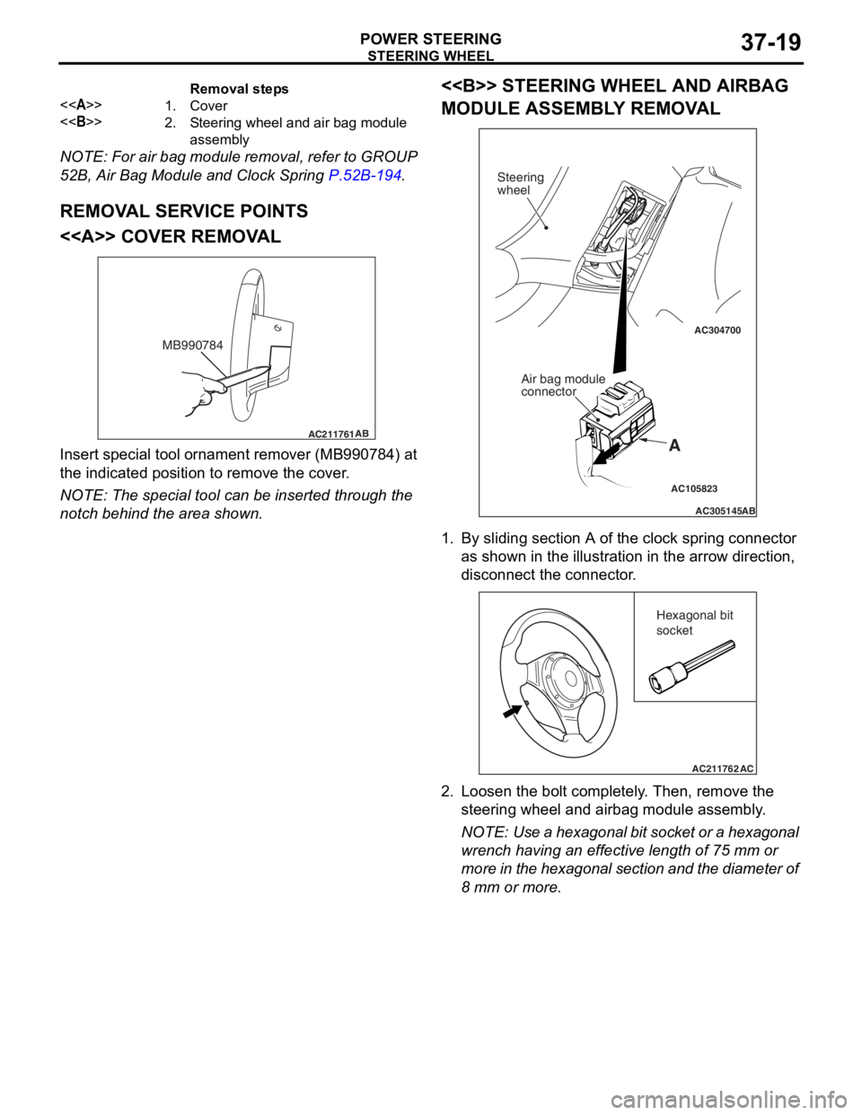
<> STEERING WHEEL AND AIRBAG
MODULE ASSEMBL
Y REMOV A L
AC105823
AC304700
AC305145AB
A
Steering
wheel
Air bag module
connector
1.By slidin g se ctio n A of the clock spring connector
a s sh own in the illustration in the arro w direction ,
d i sconne ct the con necto r .
AC211762AC
Hexagonal bit
socket
2.L oose n the b o lt comp letely . Then , remo ve th e
steering wheel and airbag mod u le a s sembly .
NOTE: Use a hexagon al b i t socket o r a h e xag onal
wren
ch ha vin g an e ffective lengt h of 75 mm or
mo
re in the hexagonal section and t he diameter of
8
mm
or mo re.
Page 254 of 800
AC304921AC
57 ± 7 N·m 15 ± 3 N·m
70 ± 10 N·m
3
5 2
4
1
67
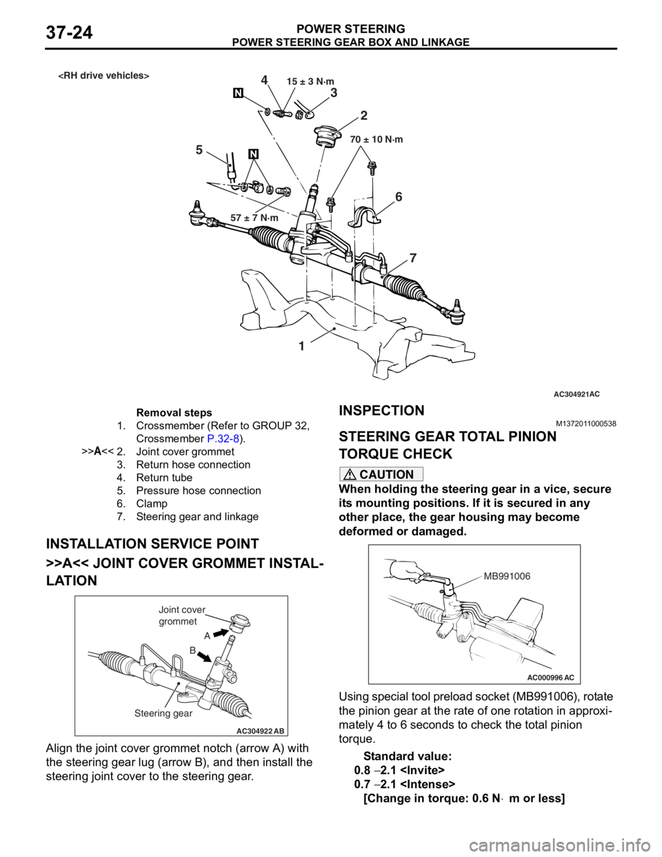
Removal steps
1.Crossmember (Refer to GROUP 32,
Crossmember
P.32-8).
>>A<<2.Joint cover grommet
3.Return hose connection
4.Return tube
5.Pressure hose connection
6.Clamp
7.Steering gear and linkage
PO WE R STEER ING GEAR BOX AND LINK AGE
POWER ST E E RING37-24
INSTALLA T ION SER VICE POINT
>>A<< JOINT COVER GROMMET INST AL-
LATION
AC304922AB
A
B
Joint cover
grommet
Steering gear
Align the jo int cove r grommet n o tch (arrow A) with
the steerin
g gear lug (a rrow B), and t hen inst all the
steering joint
cover to th e ste e ring gear .
INSPECTIONM137201 10 0053 8
STEERING GEAR T O T A L PINION
T
O RQUE CHECK
CAUTION
When holding the steering gear in a vice, secure
its mounting positions. If it is secured in any
other place, the gear housing may become
deformed or damaged.
AC000996 AC
MB991006
Using special tool preload socket (MB991006), rotate
the pinion gear at the rate of one rotation in approxi
-
mately 4 to 6 seconds to check the total pinion
torque.
Standard value:
0.8 − 2.1
0.7 − 2.1
[Change in torque: 0.6 N⋅m or less]
Page 260 of 800
POWER STEERING GEAR BOX AND LINKAGE
POWER STEERING37-30
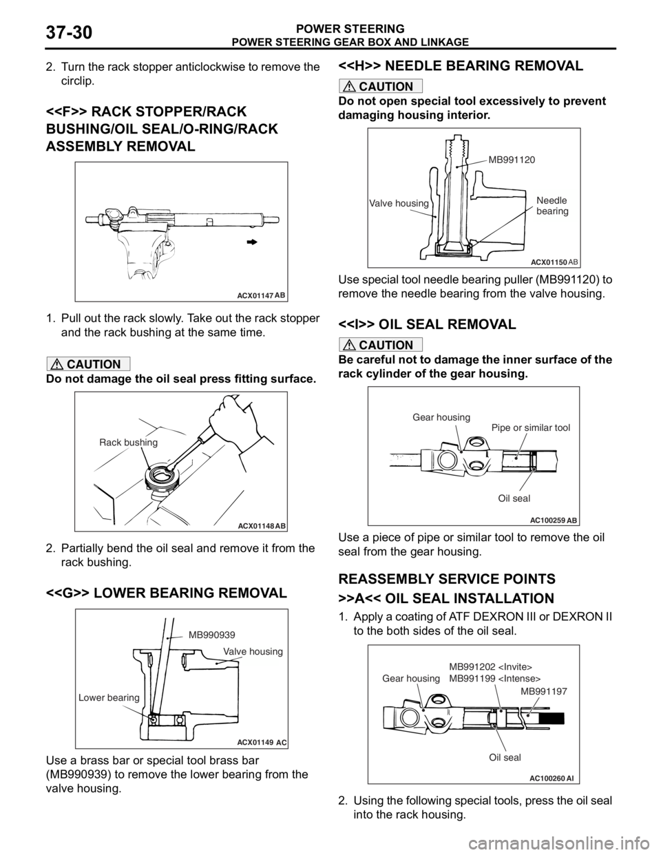
2. Turn the rack stopper anticlockwise to remove the circlip.
<
BUSHING/OIL SEAL/O-RING/RACK
ASSEMBLY REMOVAL
ACX01147 AB
1.
Pull out th e rack slo w ly . T a ke out th e rack stop per
an d the rack bushing at the same time.
CAUTION
Do not damage the oil seal press fitting surface.
ACX01148AB
Rack bushing
2. Partially bend the oil seal and remove it from the
rack bushing.
<
ACX01149
MB990939
Lower bearing
AC
Valve housing
Use a brass bar or special tool brass bar
(MB990939) to remove the lower bearing from the
valve housing.
<
CAUTION
Do not open special tool excessively to prevent
damaging housing interior.
ACX01150 AB
Valve housing MB991120Needle
bearing
Use special tool needle bearing puller (MB991120) to
remove the needle bearing from the valve housing.
<> OIL SEAL REMOVAL
CAUTION
Be careful not to damage the inner surface of the
rack cylinder of the gear housing.
AC100259
Oil seal
Pipe or similar tool
Gear housing
AB
Use a piece of pipe or simila
r tool to remove the oil
seal from the gear housing.
REASSEMBLY SERVICE POINTS
>>A<< OIL SEAL INSTALLATION
1. Apply a coating of ATF DEXRON III or DEXRON II to the both sides of the oil seal.
AC100260AI
Oil seal
MB991202
MB991199
Gear housing
MB991197
2. Using the following special tools, press the oil seal
into the rack housing.
Page 261 of 800
POWER STEERING GEAR BOX AND LINKAGE
POWER STEERING37-31
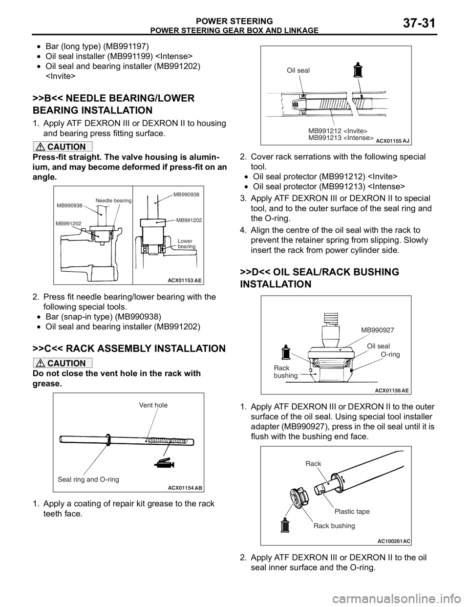
•Bar (long type) (MB991197)
•Oil seal installer (MB991199)
•Oil seal and bearing installer (MB991202)
>>B<< NEEDLE BEARING/LOWER
BEARING INSTALLATION
1. Apply ATF DEXRON III or DEXRON II to housing and bearing press fitting surface.
CAUTION
Press-fit straight. The valve housing is alumin-
ium, and may become deformed if press-fit on an
angle.
ACX01153
Needle bearing
MB990938
MB991202 MB991202
Lower
bearing
AE
MB990938
2. Press fit needle bearing/lower bearing with the
following special tools.
•Bar (snap-in type) (MB990938)
•Oil seal and bearing installer (MB991202)
>>C<< RACK ASSEMBLY INSTALLATION
CAUTION
Do not close the vent hole in the rack with
grease.
ACX01154 AB
Seal ring and O-ring Vent hole
1. Apply a coating of repair kit grease to the rack
teeth face.
ACX01155
MB991212
MB991213
AJ
Oil seal
2. Cover rack serrations with the following special tool.
•Oil seal protector (MB991212)
•Oil seal protector (MB991213)
3. Apply ATF DEXRON III or DEXRON II to special
tool, and to the outer surface of the seal ring and
the O-ring.
4. Align the centre of the oil seal with the rack to prevent the retainer spring from slipping. Slowly
insert the rack from power cylinder side.
>>D<< OIL SEAL/RACK BUSHING
INSTALLATION
ACX01156 AE
Oil seal
O-ring
MB990927
Rack
bushing
1. Apply ATF DEXRON III or DEXRON II to the outer surface of the oil seal. Using special tool installer
adapter (MB990927), press in the oil seal until it is
flush with the bushing end face.
AC100261 AC
Rack
Plastic tape
Rack bushing
2. Apply ATF DEXRON III or DEXRON II to the oil seal inner surface and the O-ring.