clock spring MITSUBISHI LANCER 2006 User Guide
[x] Cancel search | Manufacturer: MITSUBISHI, Model Year: 2006, Model line: LANCER, Model: MITSUBISHI LANCER 2006Pages: 800, PDF Size: 45.03 MB
Page 270 of 800
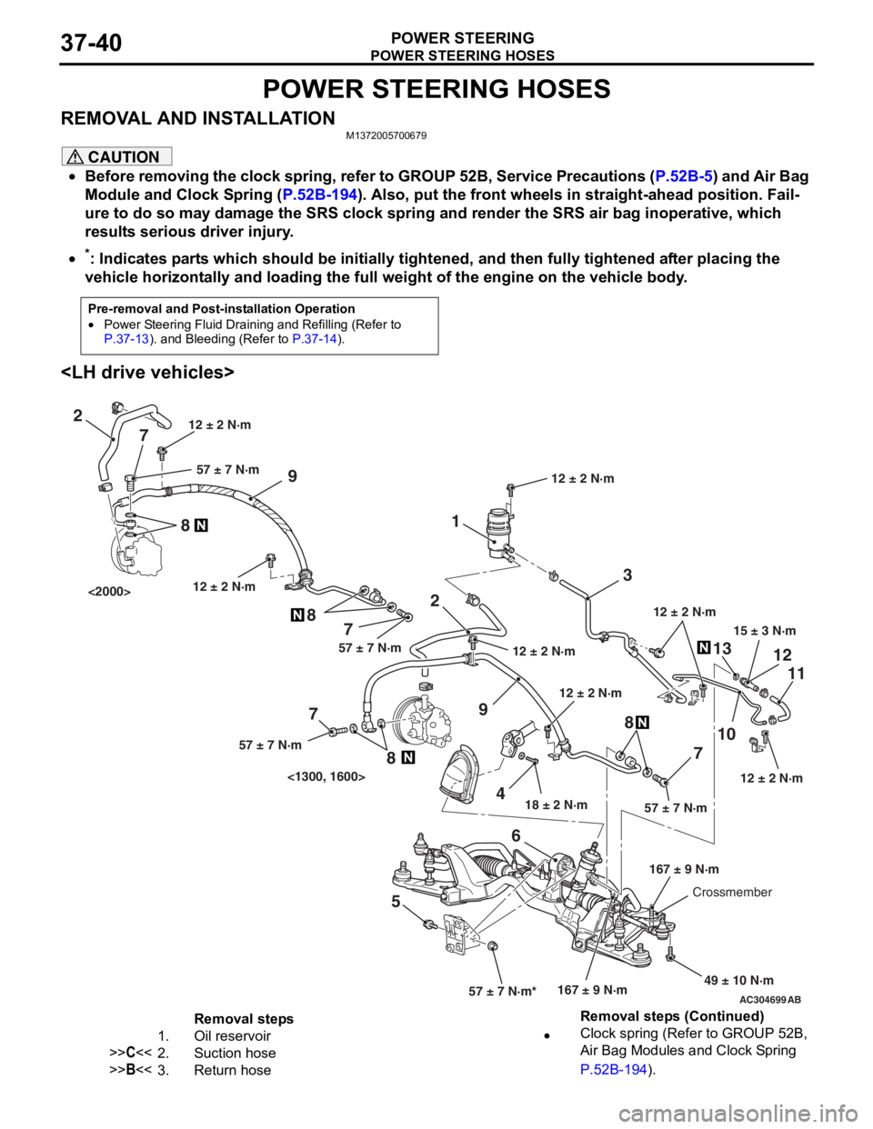
POWER STEERING HOSES
POWER STEERING37-40
POWER STEERING HOSES
REMOVAL AND INSTALLATIONM1372005700679
CAUTION
•Before removing the clock spring, refer to GROUP 52B, Service Precautions (P.52B-5) and Air Bag
Module and Clock Spring (P.52B-194). Also, put the front wheels in straight-ahead position. Fail-
ure to do so may damage the SRS clock spring and render the SRS air bag inoperative, which
results serious driver injury.
•
Pre-removal and Post-installation Operation
•Power Steering Fluid Draining and Refilling (Refer to P.37-13). and Bleeding (Refer to P.37-14).
*: Indicates parts which should be initially tightened, and then fully tightened after placing the
vehicle horizontally and loading the full weight of the engine on the vehicle body.
AC304699AB
15 ± 3 N·m
18 ± 2 N·m
167 ± 9 N·m
12 ± 2 N·m
49 ± 10 N·m
12 ± 2 N·m
57 ± 7 N·m*57 ± 7 N·m
3
1
2
9
1310
7 11
12
5 68
12 ± 2 N·m
12 ± 2 N·m
2
9
4
7
8
7
8
7
8
57 ± 7 N·m57 ± 7 N·m
57 ± 7 N·m
12 ± 2 N·m
167 ± 9 N·mCrossmember
12 ± 2 N·m
<1300, 1600>
<2000>
12 ± 2 N·m
Removal steps
1.Oil reservoir
>>C<<2.Suction hose
>>B<<3.Return hose
•Clock spring (Refer to GROUP 52B,
Air Bag Modules and Clock Spring
P.52B-194).
Removal steps (Continued)
Page 272 of 800
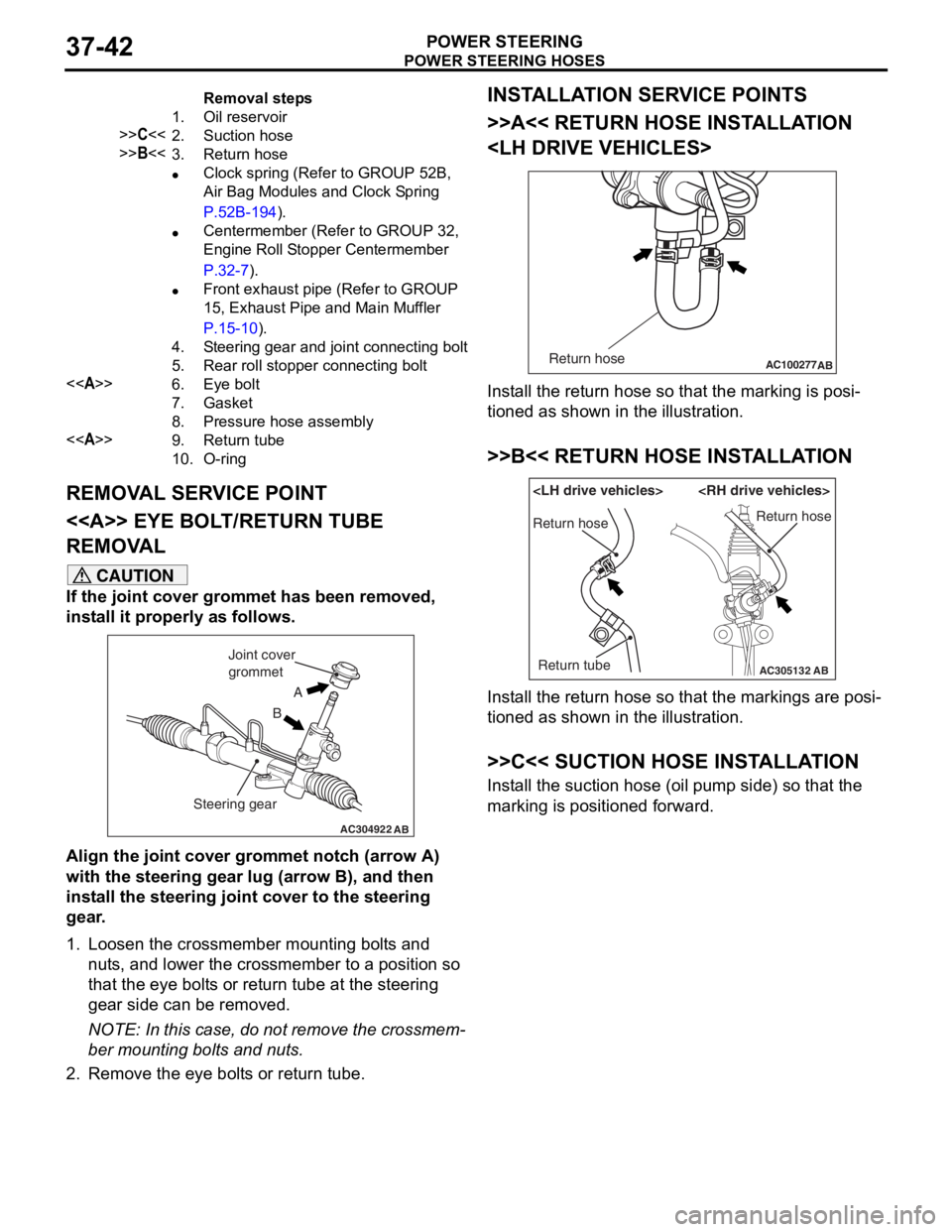
Removal steps
1.Oil reservoir
>>C<<2.Suction hose
>>B<<3.Return hose
•Clock spring (Refer to GROUP 52B,
Air Bag Modules and Clock Spring
P.52B-194).
•Centermember (Refer to GROUP 32,
Engine Roll Stopper Centermember
P.32-7).
•Front exhaust pipe (Refer to GROUP
15, Exhaust Pipe and Main Muffler
P.15-10).
4.Steering gear and joint connecting bolt
5.Rear roll stopper connecting bolt
<>6.Eye bolt
7.Gasket
8.Pressure hose assembly
<>9.Return tube
10.O-ring
POWE R STEERING HOSES
POWER S T E E RING37-42
REMOVA L SER V ICE POINT
<> EYE BOLT /RETURN TUBE
REMOV
A L
CAUTION
If the joint cover grommet has been removed,
install it properly as follows.
AC304922AB
A
B
Joint cover
grommet
Steering gear
Align the joint cover grommet notch (arrow A)
with the steering gear lug (arrow B), and then
install the steering joint cover to the steering
gear.
1. Loosen the crossmember mounting bolts and nuts, and lower the crossmember to a position so
that the eye bolts or return tube at the steering
gear side can be removed.
NOTE: In this case, do not remove the crossmem-
ber mounting bolts and nuts.
2. Remove the eye bolts or return tube.
INSTALLATION SERVICE POINTS
>>A<< RETURN HOSE INSTALLATION
AC100277 ABReturn hose
Install the return hose so that the marking is posi-
tioned as shown in the illustration.
>>B<< RETURN HOSE INSTALLATION
AC305132AB
Return hose
Return tubeReturn hose
Install the return hose so that the markings are posi-
tioned as shown in the illustration.
>>C<< SUCTION HOSE INSTALLATION
Install the suction hose (oil pump side) so that the
marking is positioned forward.
Page 440 of 800
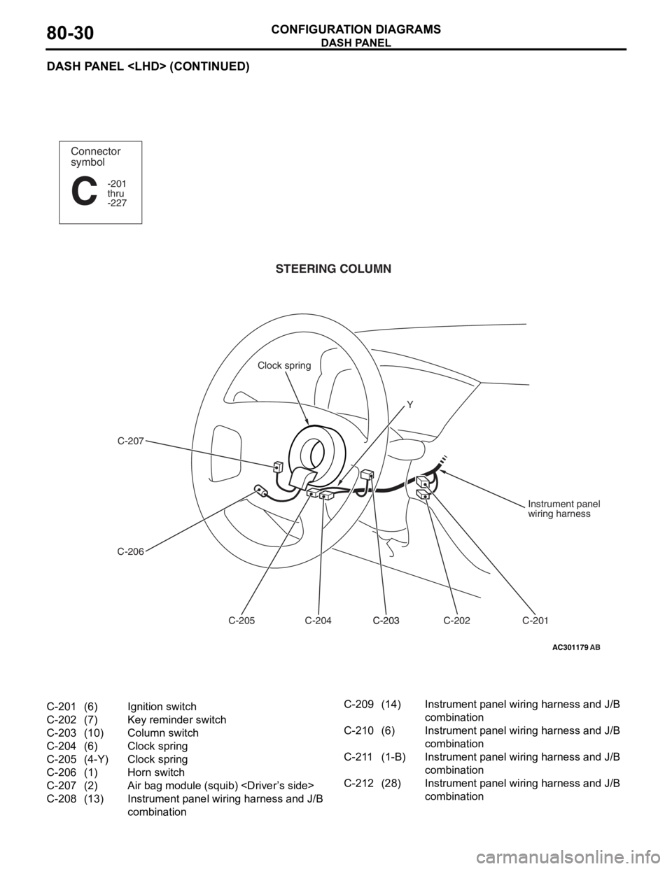
DASH PANEL
CONFIGURATION DIAGRAMS80-30
DASH PANEL
AC301179
Connector
symbol
-201
thru
-227
C
AB
STEERING COLUMN
C-207
C-206 C-201
C-202
C-203C-203
C-204
C-205 Instrument panel
wiring harness
Clock spring
Y
C-201(6)Ignition switch
C-202(7)Key reminder switch
C-203(10)Column switch
C-204(6)Clock spring
C-205(4-Y)Clock spring
C-206(1)Horn switch
C-207(2)Air bag module (squib)
C-208(13)Instrument panel wiring harness and J/B
combination
C-209(14)Instrument panel wiring harness and J/B
combination
C-210(6)Instrument panel wiring harness and J/B
combination
C-211(1-B)Instrument panel wiring harness and J/B
combination
C-212(28)Instrument panel wiring harness and J/B
combination
Page 446 of 800
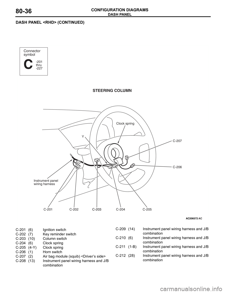
DASH PANEL
CONFIGURATION DIAGRAMS80-36
DASH PANEL
AC206572
Connector
symbol
-201
thru
-227
C
AC
STEERING COLUMN
C-207
C-206
C-205
C-204
C-203C-203
C-202
C-201
Instrument panel
wiring harness
Clock spring
Y
C-201(6)Ignition switch
C-202(7)Key reminder switch
C-203(10)Column switch
C-204(6)Clock spring
C-205(4-Y)Clock spring
C-206(1)Horn switch
C-207(2)Air bag module (squib)
C-208(13)Instrument panel wiring harness and J/B
combination
C-209(14)Instrument panel wiring harness and J/B
combination
C-210(6)Instrument panel wiring harness and J/B
combination
C-211(1-B)Instrument panel wiring harness and J/B
combination
C-212(28)Instrument panel wiring harness and J/B
combination
Page 650 of 800
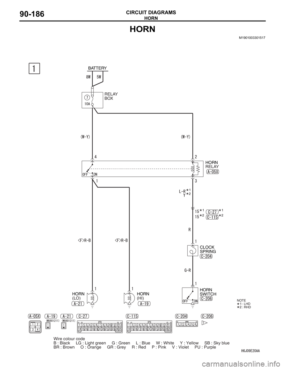
HORN
CIRCUIT DIAGRAMS90-186
HORN
M1901003301517
BATTERY
HORN
(LO)HORN
(HI) RELAY
BOX
HORN
RELAY
CLOCK
SPRING
HORN
SWITCH
NOTE
: LHD
: RHD
Wire colour code
B : Black LG : Light green G : Green L : Blue W : White Y : Yellow SB : Sky blue
BR : Brown O : Orange GR : Grey R : Red P : Pink V : Violet PU : Purple
Page 790 of 800
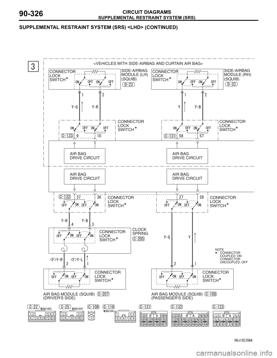
SUPPLEMENTAL RESTRAINT SYSTEM (SRS)
CIRCUIT DIAGRAMS90-326
SUPPLEMENTAL RESTRAINT SYSTEM (SRS)
SIDE-AIRBAG
MODULE (RH)
(SQUIB) CONNECTOR
LOCK
SWITCH
CONNECTOR
LOCK
SWITCHSIDE-AIRBAG
MODULE (LH)
(SQUIB)
CONNECTOR
LOCK
SWITCH
AIR BAG
DRIVE CIRCUIT AIR BAG
DRIVE CIRCUIT
AIR BAG
DRIVE CIRCUITAIR BAG
DRIVE CIRCUIT
CONNECTOR
LOCK
SWITCH
CONNECTOR
LOCK
SWITCHCONNECTOR
LOCK
SWITCH
CLOCK
SPRING
AIR BAG MODULE (SQUIB)
(DRIVER'S SIDE)AIR BAG MODULE (SQUIB)
(PASSENGER'S SIDE)CONNECTOR
LOCK
SWITCH
CONNECTOR
LOCK
SWITCH
NOTE
CONNECTOR
COUPLED: ON
CONNECTOR
UNCOUPLED: OFF :
CONNECTOR
LOCK
SWITCH
Page 796 of 800
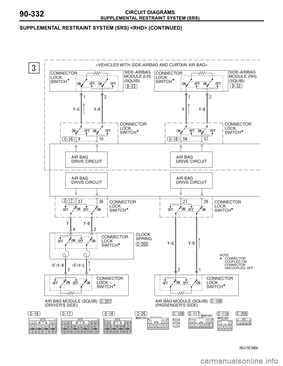
SUPPLEMENTAL RESTRAINT SYSTEM (SRS)
CIRCUIT DIAGRAMS90-332
SUPPLEMENTAL RESTRAINT SYSTEM (SRS)
SIDE-AIRBAG
MODULE (RH)
(SQUIB) CONNECTOR
LOCK
SWITCH
CONNECTOR
LOCK
SWITCHSIDE-AIRBAG
MODULE (LH)
(SQUIB)
CONNECTOR
LOCK
SWITCH
AIR BAG
DRIVE CIRCUIT AIR BAG
DRIVE CIRCUIT
AIR BAG
DRIVE CIRCUITAIR BAG
DRIVE CIRCUIT
CONNECTOR
LOCK
SWITCH
CONNECTOR
LOCK
SWITCH
CONNECTOR
LOCK
SWITCHCONNECTOR
LOCK
SWITCH
CLOCK
SPRING
AIR BAG MODULE (SQUIB)
(DRIVER'S SIDE)AIR BAG MODULE (SQUIB)
(PASSENGER'S SIDE)CONNECTOR
LOCK
SWITCH
CONNECTOR
LOCK
SWITCH
NOTE
CONNECTOR
COUPLED: ON
CONNECTOR
UNCOUPLED: OFF :