Egr MITSUBISHI LANCER 2006 Owner's Manual
[x] Cancel search | Manufacturer: MITSUBISHI, Model Year: 2006, Model line: LANCER, Model: MITSUBISHI LANCER 2006Pages: 800, PDF Size: 45.03 MB
Page 350 of 800
DOOR SASH TAPE
EXTERIOR51-18
INSTALLATION SERVICE POINT
>>A<< DOOR SASH TAPES INSTALLA-
TION
CAUTION
•The ambient temperature should be 20 to
30
°C. Ensure that the working area is clean.
Ideally, the tape application should be done at
ambient temperature of 25
°C.
•If ambient temperature is less than 15°C, heat
the tape and application surface to a tempera
-
ture of 20 to 30°C. If ambient temperature is
35
°C or higher, cool down them. The adhe-
sive property of the tape is deteriorated at low
temperature, so the tape may come adrift eas
-
ily. Meanwhile, it gets softened at hot temper-
ature.
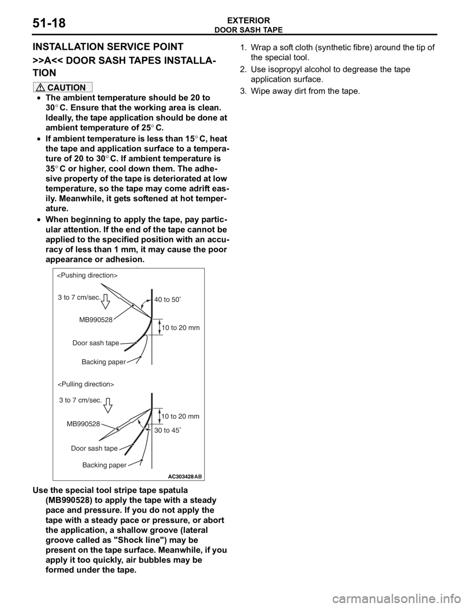
•When beginning to apply the tape, pay partic-
ular attention. If the end of the tape cannot be
applied to the specified position with an accu
-
racy of less than 1 mm, it may cause the poor
appearance or adhesion.
•
AC303428
40 to 50˚
30 to 45˚
10 to 20 mm
10 to 20 mm
AB
MB990528
MB990528 Door sash tapeDoor sash tape
Backing paper
Backing paper
3 to 7 cm/sec.
Use the special tool stripe tape spatula (MB990528) to apply the tape with a steady
pace and pressure. If you do not apply the
tape with a steady pace or pressure, or abort
the application, a shallow groove (lateral
groove called as "Shock line") may be
present on the tape surface. Meanwhile, if you
apply it too quickly, air bubbles may be
formed under the tape.
1. Wrap a soft cloth (synthetic fibre) around the tip of
the special tool.
2. Use isopropyl alcohol to degrease the tape application surface.
3. Wipe away dirt from the tape.
Page 354 of 800
DOOR SASH TAPE
EXTERIOR51-22
INSTALLATION SERVICE POINT
>>A<< DOOR SASH TAPES INSTALLA-
TION
CAUTION
•The ambient temperature should be 20 to
30
°C. Ensure that the working area is clean.
Ideally, the tape application should be done at
ambient temperature of 25
°C.
•If ambient temperature is less than 15°C, heat
the tape and application surface to a tempera
-
ture of 20 to 30°C. If ambient temperature is
35
°C or higher, cool down them. The adhe-
sive property of the tape is deteriorated at low
temperature, so the tape may come adrift eas
-
ily. Meanwhile, it gets softened at hot temper-
ature.
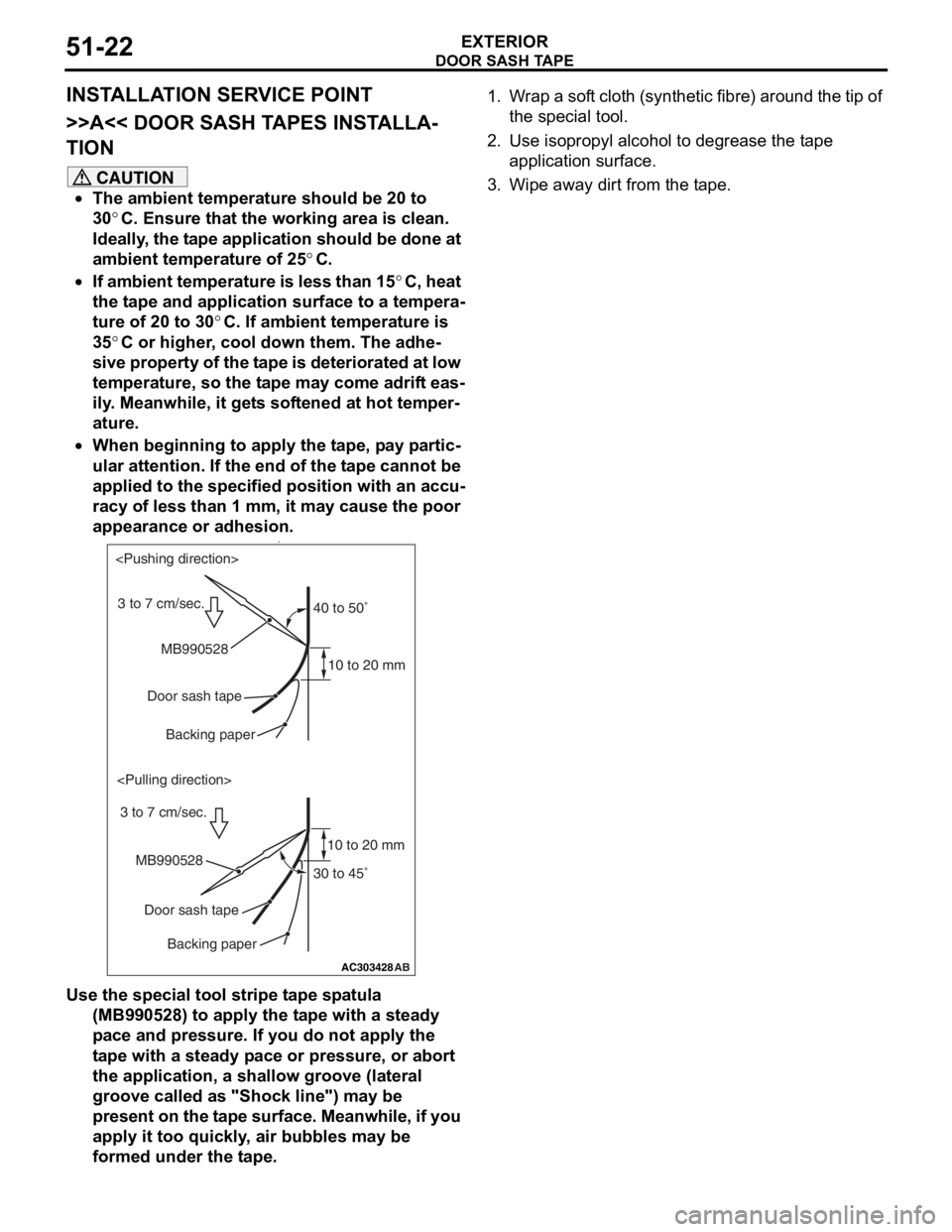
•When beginning to apply the tape, pay partic-
ular attention. If the end of the tape cannot be
applied to the specified position with an accu
-
racy of less than 1 mm, it may cause the poor
appearance or adhesion.
•
AC303428
40 to 50˚
30 to 45˚
10 to 20 mm
10 to 20 mm
AB
MB990528
MB990528 Door sash tapeDoor sash tape
Backing paper
Backing paper
3 to 7 cm/sec.
Use the special tool stripe tape spatula (MB990528) to apply the tape with a steady
pace and pressure. If you do not apply the
tape with a steady pace or pressure, or abort
the application, a shallow groove (lateral
groove called as "Shock line") may be
present on the tape surface. Meanwhile, if you
apply it too quickly, air bubbles may be
formed under the tape.
1. Wrap a soft cloth (synthetic fibre) around the tip of
the special tool.
2. Use isopropyl alcohol to degrease the tape application surface.
3. Wipe away dirt from the tape.
Page 403 of 800
SOLENOID VALVE
COMPONENT LOCATIONS70-13
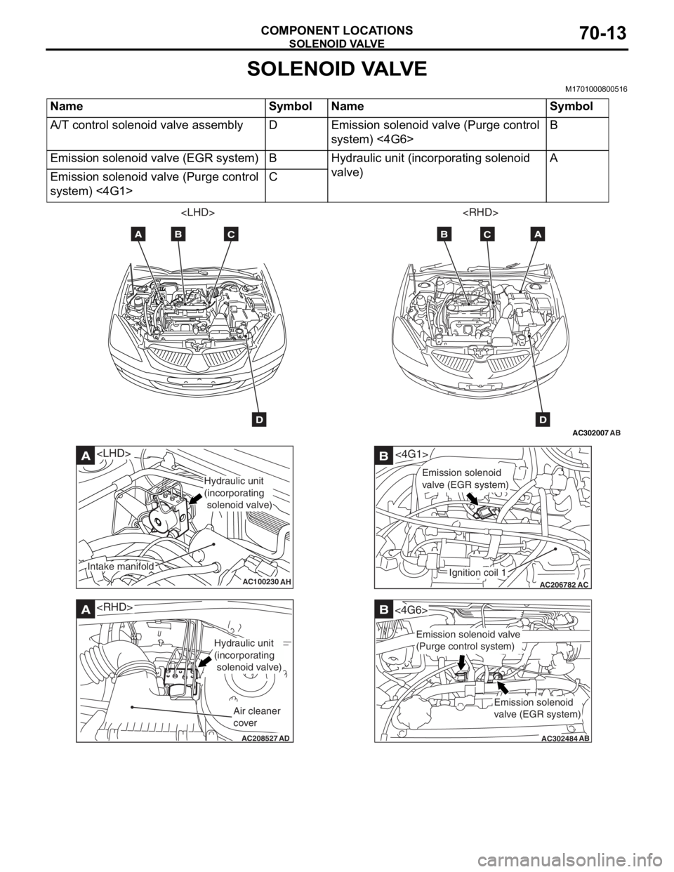
SOLENOID VALVE
M1701000800516
NameSymbolNameSymbol
A/T control solenoid valve assemblyDEmission solenoid valve (Purge control
system) <4G6>B
Emission solenoid valve (EGR system)BHydraulic unit (incorporating solenoid
valve)A
Emission solenoid valve (Purge control
system) <4G1>C
AC302007
AB
AB
ABC
D
C
D
AC100230
A
AH
Hydraulic unit
(incorporating
solenoid valve)
Intake manifold
AC208527
A
AD
Hydraulic unit
(incorporating
solenoid valve)
Air cleaner
cover
AC206782
<4G1>B
AC
Ignition coil 1
Emission solenoid
valve (EGR system)
AC302484
B
AB
<4G6>
Emission solenoid
valve (EGR system)
Emission solenoid valve
(Purge control system)
Page 422 of 800

ENGINE AND TRANSMISSION
CONFIGURATION DIAGRAMS80-12
ENGINE AND TRANSMISSION <4G1-MPI (LHD)> (CONTINUED)
AC301129AE
B-118B-101 B-102
B-113
B-114
B-115
B-116 B-117
Earth cable
Control wiring
harness
Connector colour
code
B : Black
BR : Brown
G : Green
GR : Grey
L : Blue
None : Milk white
O : Orange
R : Red
V : Violet
Y : Yellow
Connector
symbol
-101
thru
-118
B
*
B-101(2-BR)Emission solenoid valve (EGR system)
B-102(4-GR)Inlet manifold absolu te pressure sensor
B-103(6-B)Throttle body idle speed control servo
B-104(3-GR)Ignition coil 1
B-105(2-B)Emission solenoid va lve (Purge control
system)
B-107(3-B)Camshaft position sensor
B-108(3-GR)Output shaft speed sensor
B-109(3-B)Input shaft speed sensor
B-110(2-B)Back-up lamp switch
B-111(2-B)Water temperature sensor unit
Page 426 of 800
ENGINE AND TRANSMISSION
CONFIGURATION DIAGRAMS80-16
ENGINE AND TRANSMISSION <4G1-MPI (RHD)> (CONTINUED)
AC301132AE
B-117B-101 B-102
B-113
B-114
B-115
B-116
Earth cable
Control wiring
harness
Connector colour
code
B : Black
BR : Brown
G : Green
GR : Grey
L : Blue
None : Milk white
O : Orange
R : Red
V : Violet
Y : Yellow
Connector
symbol
-101
thru
-118
B
*
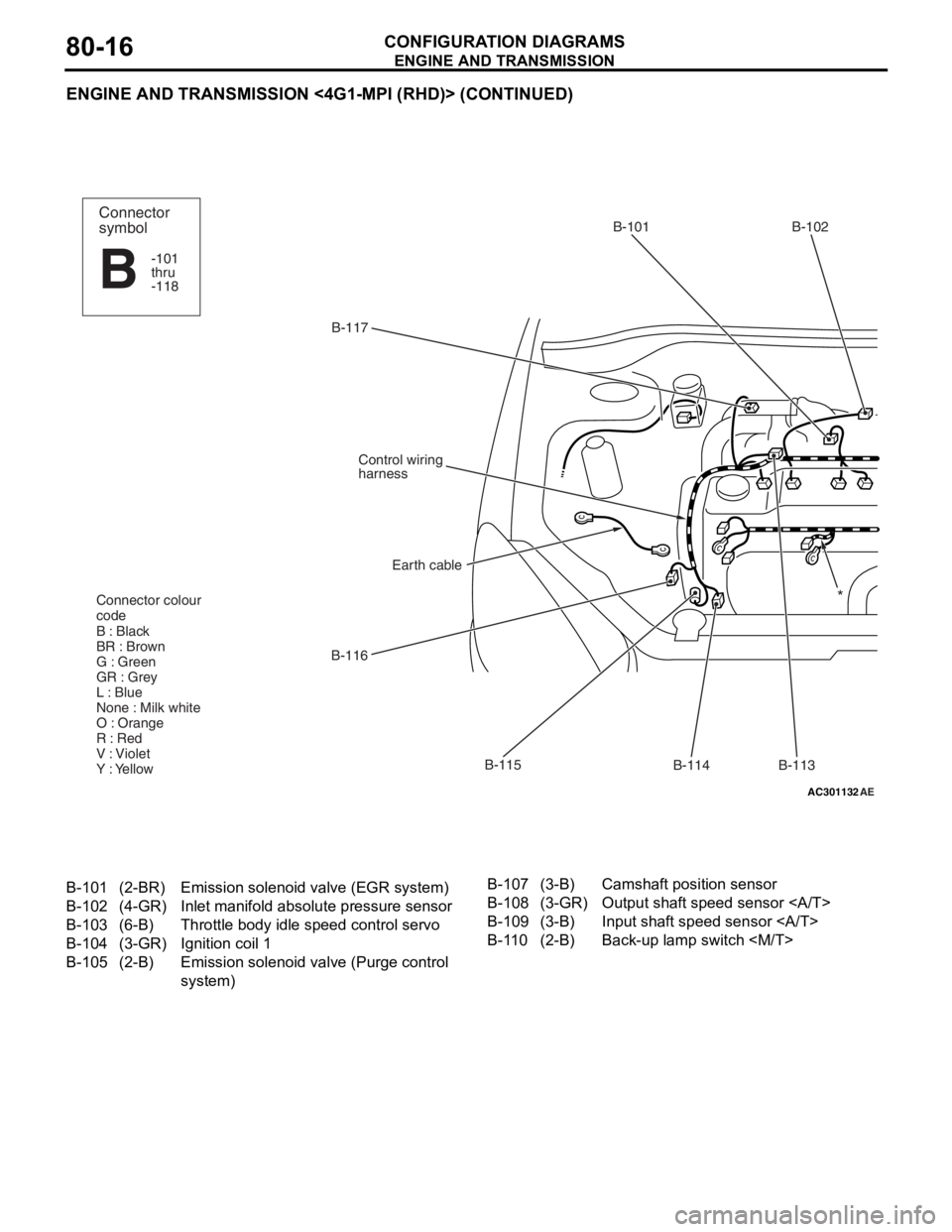
B-101(2-BR)Emission solenoid valve (EGR system)
B-102(4-GR)Inlet manifold absolu te pressure sensor
B-103(6-B)Throttle body idle speed control servo
B-104(3-GR)Ignition coil 1
B-105(2-B)Emission solenoid va lve (Purge control
system)
B-107(3-B)Camshaft position sensor
B-108(3-GR)Output shaft speed sensor
B-109(3-B)Input shaft speed sensor
B-110(2-B)Back-up lamp switch
Page 430 of 800
ENGINE AND TRANSMISSION
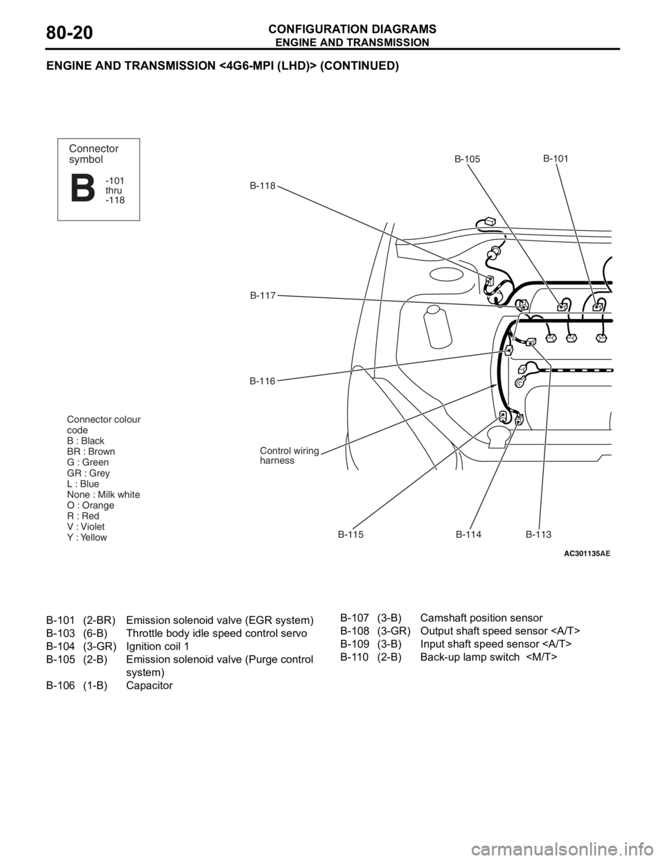
CONFIGURATION DIAGRAMS80-20
ENGINE AND TRANSMISSION <4G6-MPI (LHD)> (CONTINUED)
AC301135AE
B-118B-101
B-114
B-115
B-116
B-117
Control wiring
harness
Connector colour
code
B : Black
BR : Brown
G : Green
GR : Grey
L : Blue
None : Milk white
O : Orange
R : Red
V : Violet
Y : Yellow
B-113
B-105Connector
symbol
-101
thru
-118
B
B-101(2-BR)Emission solenoid
valve (EGR system)
B-103(6-B)Throttle body idle speed control servo
B-104(3-GR)Ignition coil 1
B-105(2-B)Emission solenoid va lve (Purge control
system)
B-106(1-B)Capacitor
B-107(3-B)Camshaft position sensor
B-108(3-GR)Output shaft speed sensor
B-109(3-B)Input shaft speed sensor
B-110(2-B)Back-up lamp switch
Page 434 of 800
ENGINE AND TRANSMISSION
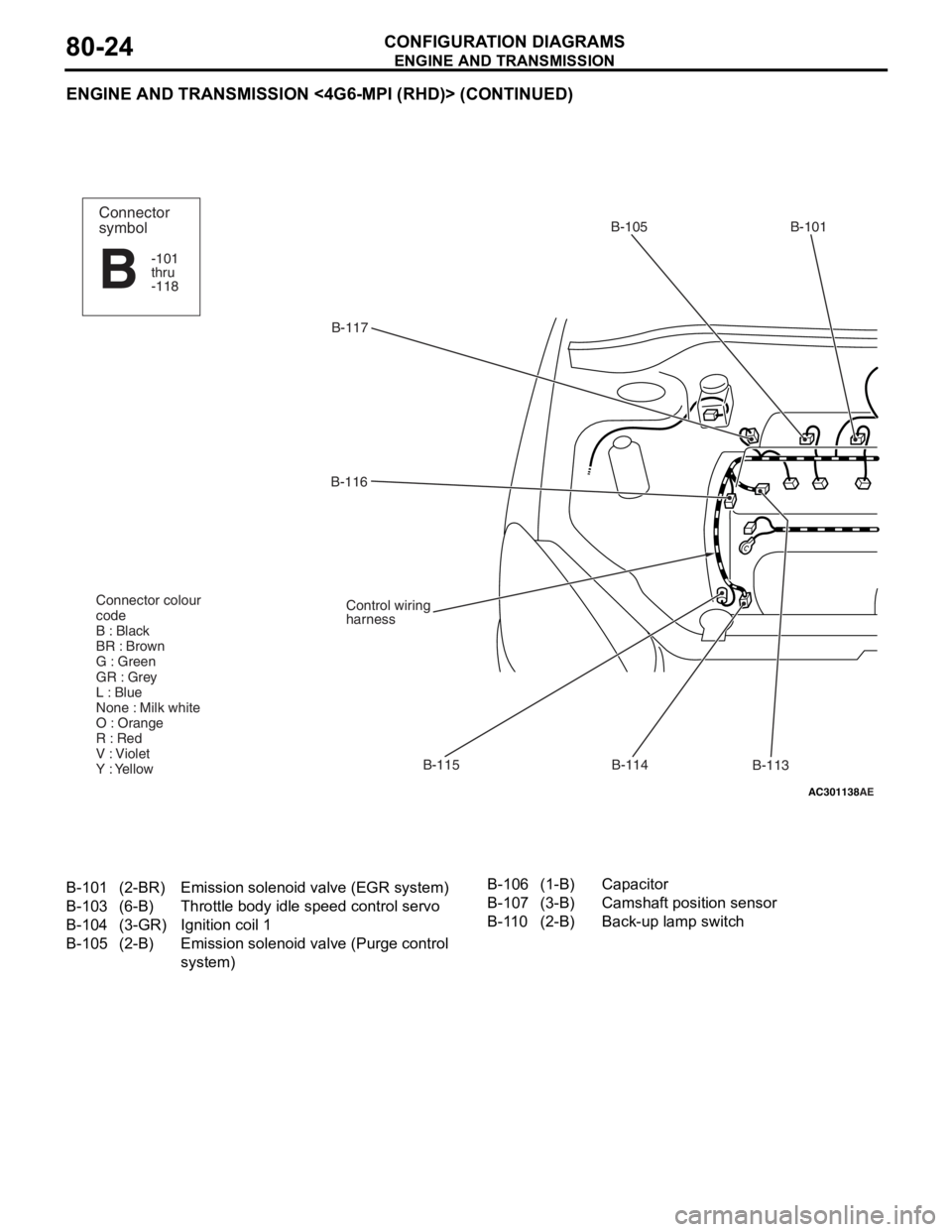
CONFIGURATION DIAGRAMS80-24
ENGINE AND TRANSMISSION <4G6-MPI (RHD)> (CONTINUED)
AC301138AE
B-117B-105 B-101
B-113
B-114
B-115
B-116
Control wiring
harness
Connector colour
code
B : Black
BR : Brown
G : Green
GR : Grey
L : Blue
None : Milk white
O : Orange
R : Red
V : Violet
Y : Yellow
Connector
symbol
-101
thru
-118
B
B-101(2-BR)Emission solenoid
valve (EGR system)
B-103(6-B)Throttle body idle speed control servo
B-104(3-GR)Ignition coil 1
B-105(2-B)Emission solenoid va lve (Purge control
system)
B-106(1-B)Capacitor
B-107(3-B)Camshaft position sensor
B-110(2-B)Back-up lamp switch
Page 482 of 800

CENTRALIZED JUNCTION
CIRCUIT DIAGRAMS90-18
CENTRALIZED JUNCTION
M1901000301477
FUSIBLE LINK AND FUSE
ENGINE COMPARTMENT
No.Power supply circuitNameRated
capacity (A)Housing
colourLoad circuit
1Battery/ Alternator
(Fusible link No.26)Fusible
link60YellowFuse No.15, 16, 18, 19, 20 (in junction
block) circuit
250RedFan controller
360YellowABS-ECU
440GreenIgnition switch circuit
530PinkPower window main switch and power
window sub switch
6Fuse15BlueFront fog lamp, front fog lamp
indicator lamp, front fog lamp relay
and spare connector (for front fog
lamp)
710RedHorn relay and horn
820YellowAir cleaner air flow sensor, camshaft
position sensor, emission solenoid
valve (EGR system), emission
solenoid valve (purge control system),
engine-A/T-ECU, engine-ECU, engine
control oxygen sensor, engine control
relay, engine crank angle sensor, fan
control relay, fuel injector, ignition coil
relay, immobilizer-ECU and throttle
body idle speed control servo
910RedA/C compressor
1015BlueABS-ECU, engine-A/T-ECU, high
mount stop lamp and rear combination
lamp
1115BlueAccessory socket
127.5BrownAlternator
1310RedETACS-ECU, front turn signal lamp,
rear combination lamp, side turn
signal lamp and turn signal indicator
lamp
1420YellowA/T control solenoid valve assembly
and engine-A/T-ECU
1515BlueFuel pump
16Front-ECU
(Headlamp relay: HI)10RedHeadlamp (RH)
1710RedHeadlamp (LH) and high beam
indicator lamp
18Front-ECU
(Headlamp relay: LO)10RedHeadlamp (RH)
1910RedHeadlamp (LH), headlamp assembly
and headlamp levelling switch
Page 515 of 800
ENGINE CONTROL SYSTEM
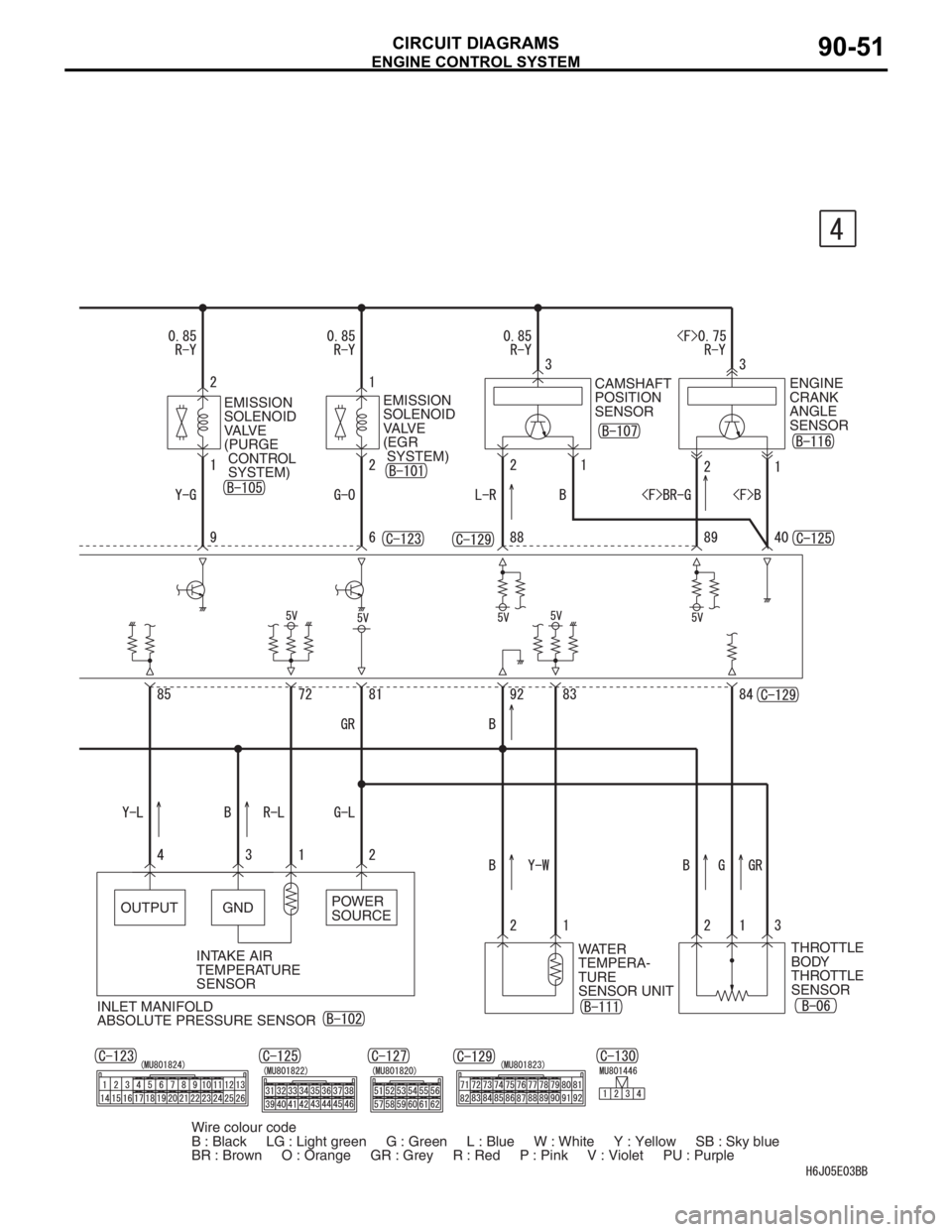
CIRCUIT DIAGRAMS90-51
INLET MANIFOLD
ABSOLUTE PRESSURE SENSORWATER
TEMPERA-
TURE
SENSOR UNITTHROTTLE
BODY
THROTTLE
SENSOR EMISSION
SOLENOID
VALVE
(PURGE
CONTROL
SYSTEM)EMISSION
SOLENOID
VALVE
(EGR
SYSTEM)CAMSHAFT
POSITION
SENSORENGINE
CRANK
ANGLE
SENSOR
OUTPUT GNDPOWER
SOURCE
INTAKE AIR
TEMPERATURE
SENSOR
Wire colour code
B : Black LG : Light green G : Green L : Blue W : White Y : Yellow SB : Sky blue
BR : Brown O : Orange GR : Grey R : Red P : Pink V : Violet PU : Purple
Page 521 of 800
ENGINE CONTROL SYSTEM
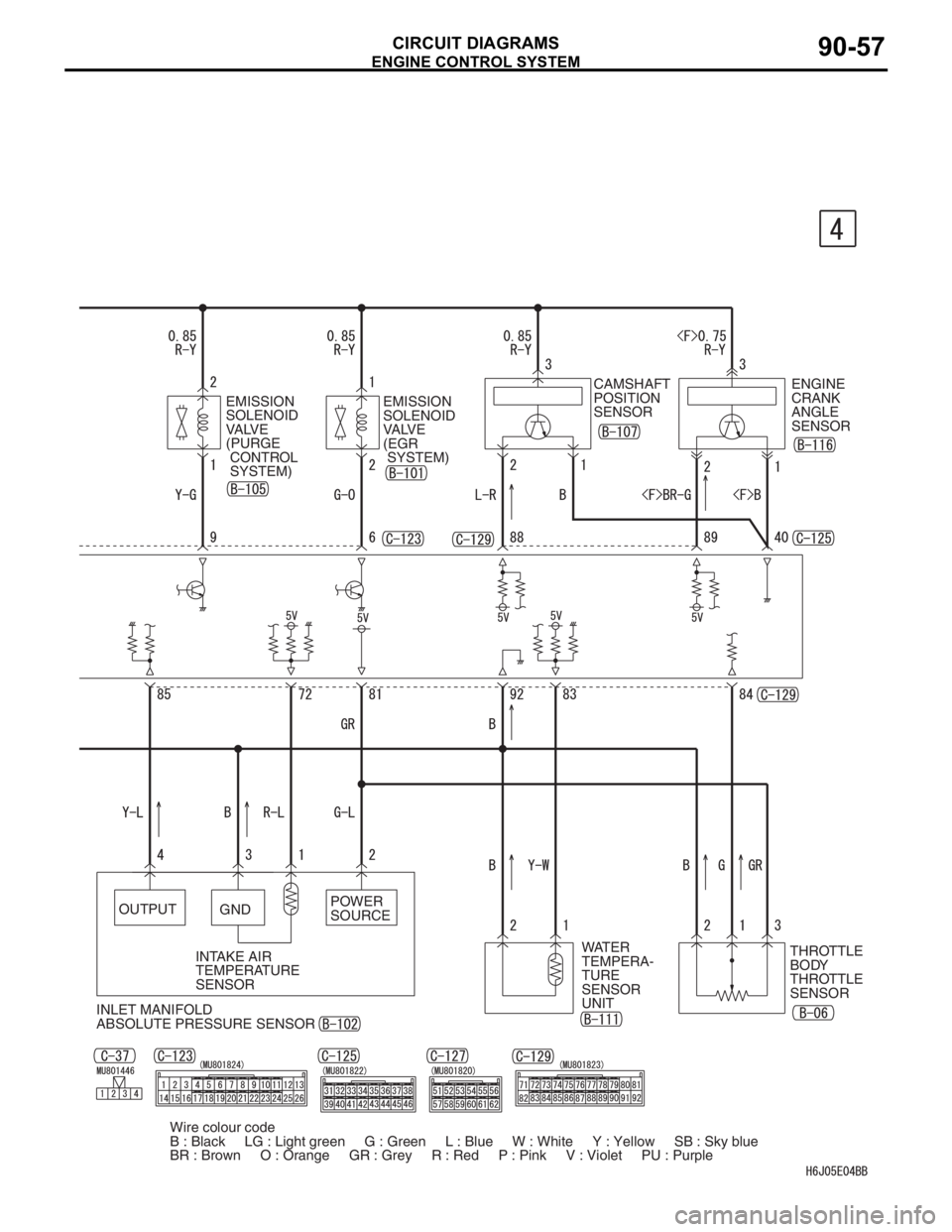
CIRCUIT DIAGRAMS90-57
CAMSHAFT
POSITION
SENSOR
OUTPUT
GNDPOWER
SOURCE
INTAKE AIR
TEMPERATURE
SENSOREMISSION
SOLENOID
VALVE
(PURGE
CONTROL
SYSTEM)EMISSION
SOLENOID
VALVE
(EGR
SYSTEM)ENGINE
CRANK
ANGLE
SENSOR
INLET MANIFOLD
ABSOLUTE PRESSURE SENSORWATER
TEMPERA-
TURE
SENSOR
UNITTHROTTLE
BODY
THROTTLE
SENSOR
Wire colour code
B : Black LG : Light green G : Green L : Blue W : White Y : Yellow SB : Sky blue
BR : Brown O : Orange GR : Grey R : Red P : Pink V : Violet PU : Purple