Egr MITSUBISHI LANCER 2006 User Guide
[x] Cancel search | Manufacturer: MITSUBISHI, Model Year: 2006, Model line: LANCER, Model: MITSUBISHI LANCER 2006Pages: 800, PDF Size: 45.03 MB
Page 120 of 800
AK302349AB
<4G6>EGR
control
Solenoid
valve
EGR valve OFF
ON
Control
relay
Battery Engine-ECU
Barometric pressure
sensor
Air flow sensor
Engine coolant
temperature sensor
Crank angle sensor
EMISSION CONTROL
ENGINE AND E M ISSION CON T ROL17-14
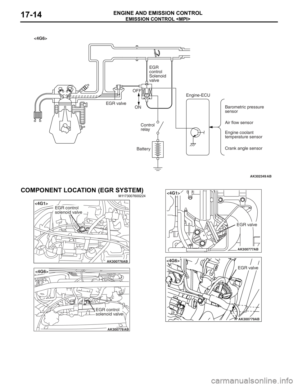
COMPONENT LOCATION (EGR SYSTEM)
M1173 0076 0022 4
AK300776
<4G1>
AB
EGR control
solenoid valve
AK300778
<4G6>
AB
EGR control
solenoid valve
AK300777
<4G1>
AB
EGR valve
AK300779AB
<4G6>
EGR valve
Page 121 of 800
EMISSION CONTROL
ENGINE AND EMISSION CONTROL17-15
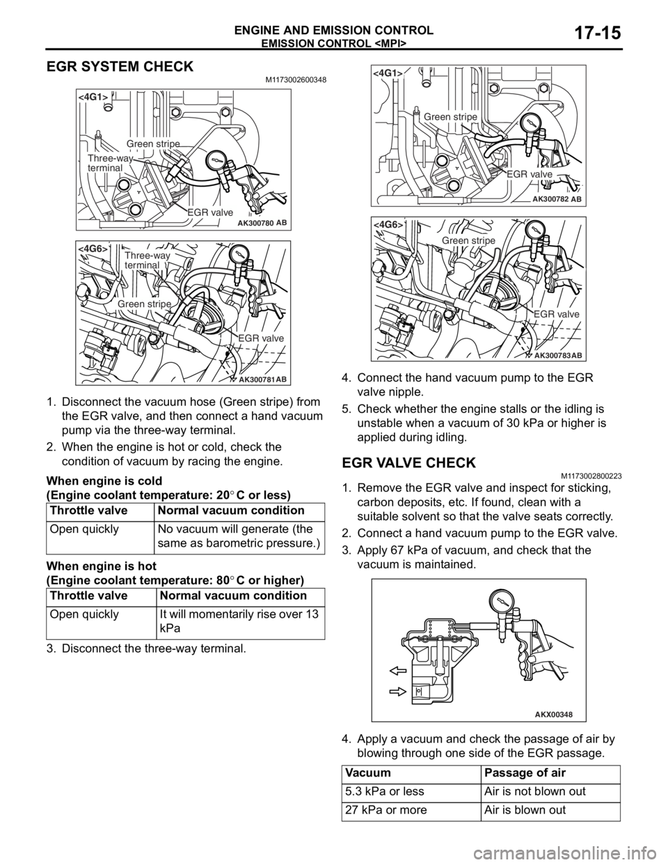
EGR SYSTEM CHECK
M1173002600348
AK300780AB
<4G1>
EGR valve
Green stripe
Three-way
terminal
AK300781AB
<4G6>
EGR valve
Green stripe
Three-way
terminal
1.Disco nnect the vacu um ho se (Green stripe) from
th e EGR valve, a nd th en connect a hand vacuum
pu mp via t he thre e-way te rmin al.
2.Wh en the engine is hot o r cold, check the
condition of va cuum by racing the engine.
When engine is c o ld
(Eng ine coo lant tem perature: 20°C or less)
Throttle valveNormal vacuum co ndition
Open quicklyNo va cuum will gene rate (th e
same as baro
m etric pre s sure.)
When engine is h o t
(Eng ine coo lant tem perature: 80°C or higher)
Throttle valveNormal vacuum c ondition
Open quicklyIt will mo me nt a r i l y rise o v er 13
kPa
3.Disco nnect the th ree-way t e rminal.
AK300782AB
<4G1>
EGR valve
Green stripe
AK300783AB
<4G6>
EGR valve
Green stripe
4.Conn ect the han d va cuum pump to t he EGR
valve nipple.
5.Check whe t her th e engine st alls or the idling is
u n st able when a vacuum of 30 kPa or h i gher is
a pplied during idling.
EGR V A L V E CHECKM1173 0028 0022 3
1.Remove the EGR valve an d inspect for stickin g ,
carbon deposit s, e t c. If found , clean with a
suit able so lve n t so that th e va lve seat s corre ctly .
2.Conn ect a hand vacuum pump to the EGR va lve .
3.App l y 6 7 kPa of va cuum, and check t hat the
vacu um is maint a ined.
AKX00348
4.App l y a vacuum and chec k th e p a ssage of air by
b l owing throug h one side of the EGR p a ssage.
VacuumPassage of air
5.3 kPa or lessAir is not blown out
27 kPa or moreAir is blown out
Page 122 of 800
EMISSION CONTROL
ENGINE AND EMISSION CONTROL17-16
5. Replace the gasket, and tighten to the specified torque.
Tightening torque:
<4G1> 21 ± 4 N⋅m
<4G6> 20 ± 2 N⋅m
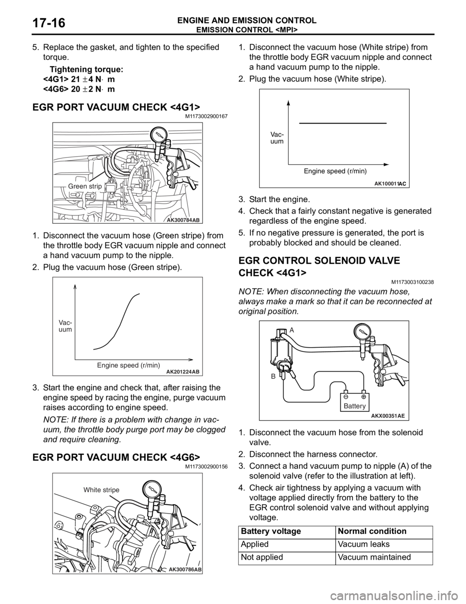
EGR PORT VACUUM CHECK <4G1>M1173002900167
AK300784AB
Green strip
1.Disco nnect the vacu um ho se (Green stripe) from
th e t h ro tt le b o d y EGR va cuu m ni pp le an d co nn ec t
a hand vacu um p u mp to the nipple.
2.Plu g the vacuum hose (Gree n stripe).
AK201224AB
Vac-
uum
Engine speed (r/min)
3.S t art the engin e and check t hat, af ter ra ising th e
engine spe ed by ra cin g the e ngine, p u rge vacuu m
raises according to engine speed.
NOTE: If ther e is a prob lem with change in vac-
uum, the t h rottle bod y p u rge port may be clo gged
an
d requ ire clean ing.
EGR PORT VA CUUM CHECK <4G6>M1173 0029 0015 6
AK300786AB
White stripe
1.Disco nnect the vacu um h o se (W hite strip e ) from
th e t h ro tt le b o d y EGR va cuu m ni pp le an d co nn ec t
a hand vacuum p u mp to the nipple.
2.Plug the vacuum hose (White stripe).
AK100011AC
Vac-
uum
Engine speed (r/min)
3.S t art the engine.
4.Check that a fairly const a nt n egative is gene rated
re gardle s s of the engine sp eed.
5.If no neg ative pressur e is genera t ed, th e port is
p r obably blocked an d sh ould be cleane d.
EGR CONTROL SOLENOID VA L V E
CHECK <
4 G1 >
M1173 0031 0023 8
NOTE: Whe n discon nect i ng th e va cuum hose,
always make a mark so th at it can be reconnected at
original p o sition.
AKX00351
A
B
AE
Battery
1. Disco nnect the vacu um h o se f r om th e solenoid
valve.
2.Disco nnect the ha rness connector .
3.Con nect a ha nd vacu um pump to nipp le (A) of the
solen o id valve (ref e r to th e ill ust r ation at le f t ).
4.Check a i r tightness b y ap plying a vacuum with
volt age applied d i rectly from t he batt e ry to the
EGR cont rol solen o id valve and withou t applyin g
volt age .
Battery voltageNormal condition
AppliedVa c u u m l e a k s
Not appliedVacuum maintained
Page 123 of 800
AKX00352
EMISSI ON CONTROL
ENGINE AND E M ISSION CON T R O L17-17
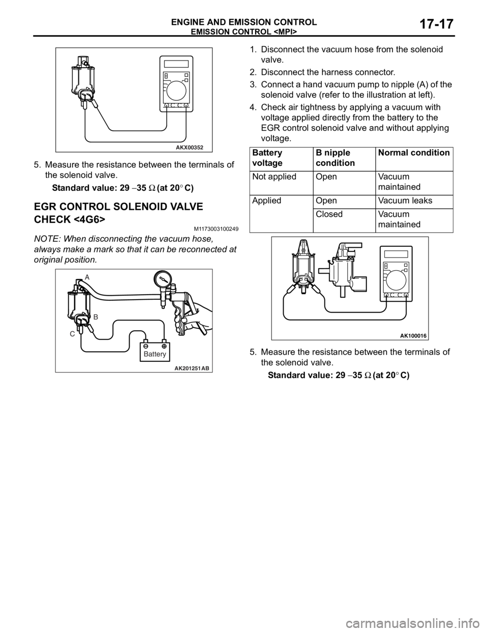
5.Measure the resist ance between the te rmin als of
th e solenoid va lve .
St andard va lue: 29 − 35 Ω (at 20°C)
EGR CONTROL SOLENOID V A L V E
CHECK <
4 G6>
M1173 0031 0024 9
NOTE: Whe n discon nect i ng th e va cuum hose,
always
make a mark so th at it can be reconnected at
original p o sition.
AK201251AB
A
B
C
Battery
1.Disco nnect the vacu um h o se f r om th e solenoid
valve.
2.Disco nnect the ha rness connector .
3.Con nect a ha nd vacu um pump to nipp le (A) of the
solen o id valve (ref e r to th e ill ust r ation at le f t ).
4.Check a i r tightness b y ap plying a vacuum with
volt age applied d i rectly from t he batt e ry to the
EGR cont rol solen o id valve and withou t applyin g
volt age .
Battery
voltageB nipple
conditionNormal condition
Not appliedOpenVacuum
maintained
AppliedOpenVacuum leaks
ClosedVacuum
maintained
AK100016
5.Measure the resist ance betwee n the te rminals of
th e so lenoid valve .
St andard va lue: 29 − 35 Ω (at 20°C)
Page 124 of 800

EMISSION CONTROL
ENGINE AND EMISSION CONTROL17-18
EXHAUST GAS RECIRCULATION (EGR)
VALVE REMOVAL AND INSTALLATION
M1173010500175
Pre-removal and Post-installation Operation
Air Cleaner Assembly Removal and Installation (Refer to
GROUP 15
P.15-3).
AC208130
21 ± 4 N·m
2
1
3
N
AC
<4G1>
AC301219
20 ± 2 N·m2
1
3
N
AB
Removal steps
1.Emission vacuum hose connection2.EGR valve
3.EGR valve gasket
Removal steps (Continued)
Page 233 of 800

GENERAL INFORMATION
POWER STEERING37-3
GENERAL INFORMATION
M1372000100661
Power steering has been adopted in all vehicles to
make the steering system easier to handle.
FEATURES
•A 4-spoke steering wheel is used.
•MOMO leather-wrapped 3-spoke steering wheel
is used.
•A steering column has a shock absorbing mecha-
nism and a tilt steering mechanism.
•Integral-type rack and pinion gear with high rigid-
ity and excellent response is used.
•A vane type pump with a fluid flow rate control
system which change steering effort according to
the engine speed is used.
•The separate plastic resin oil reservoir is used to
reduce weight and to make the fluid level check
-
ing easier.
SPECIFICATIONS
ItemInviteIntense
Steering
wheelTy p e4-spoke typeMOMO leather-wrapped
3-spoke type
Outside diameter mm380365
Maximum number of turns3.193.08
Steering
columnColumn mechanismShock absorbing mechanism and Tilt steering mechanism
Power steering typeIntegral type
Oil pumpTy p eVane pump
Basic discharge amount cm3/rev.7.2 <1300, 1600>
8.1 <2000>
7.2 <1300, 1600>
8.1 <2000>
Relief pressure MPa8.88.8
Reservoir typeSeparate type (plastic)
Pressure switchEquipped
Steering
gearTy p eRack and pinion
Stroke ratio (Rack stroke/Steering
wheel maximum turning radius)45.7445.74
Rack stroke mm146141
Page 286 of 800
WINDOW GLASS
BODY42-14
CAUTION•
ACX00476AB
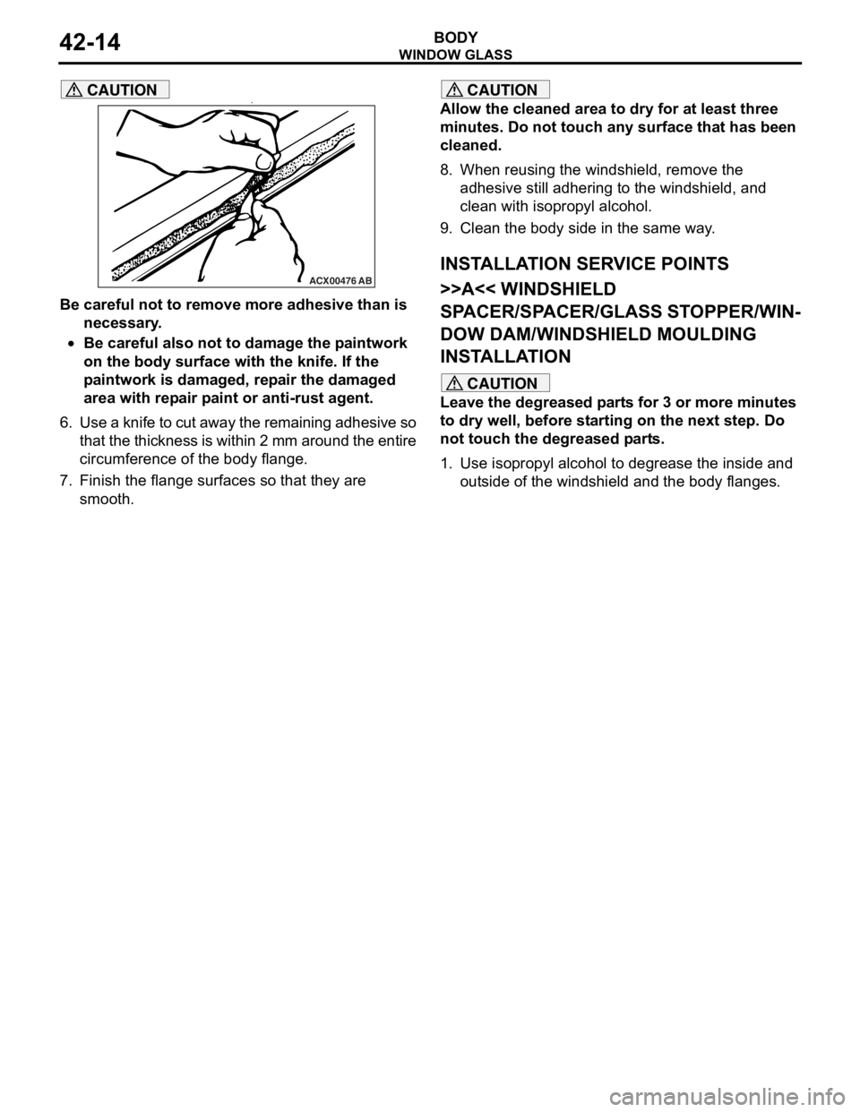
Be careful not to remove more adhesive than is
necessary.
•Be careful also not to damage the paintwork
on the body surface with the knife. If the
paintwork is damaged, repair the damaged
area with repair paint or anti-rust agent.
6. Use a knife to cut away the remaining adhesive so
that the thickness is within 2 mm around the entire
circumference of the body flange.
7. Finish the flange surfaces so that they are smooth.
CAUTION
Allow the cleaned area to dry for at least three
minutes. Do not touch any surface that has been
cleaned.
8. When reusing the windshield, remove the adhesive still adhering to the windshield, and
clean with isopropyl alcohol.
9. Clean the body side in the same way.
INSTALLATION SERVICE POINTS
>>A<< WINDSHIELD
SPACER/SPACER/GLASS STOPPER/WIN
-
DOW DAM/WINDSHIELD MOULDING
INSTALLATION
CAUTION
Leave the degreased parts for 3 or more minutes
to dry well, before starting on the next step. Do
not touch the degreased parts.
1. Use isopropyl alcohol to degrease the inside and outside of the windshi eld and the body flanges.
Page 290 of 800
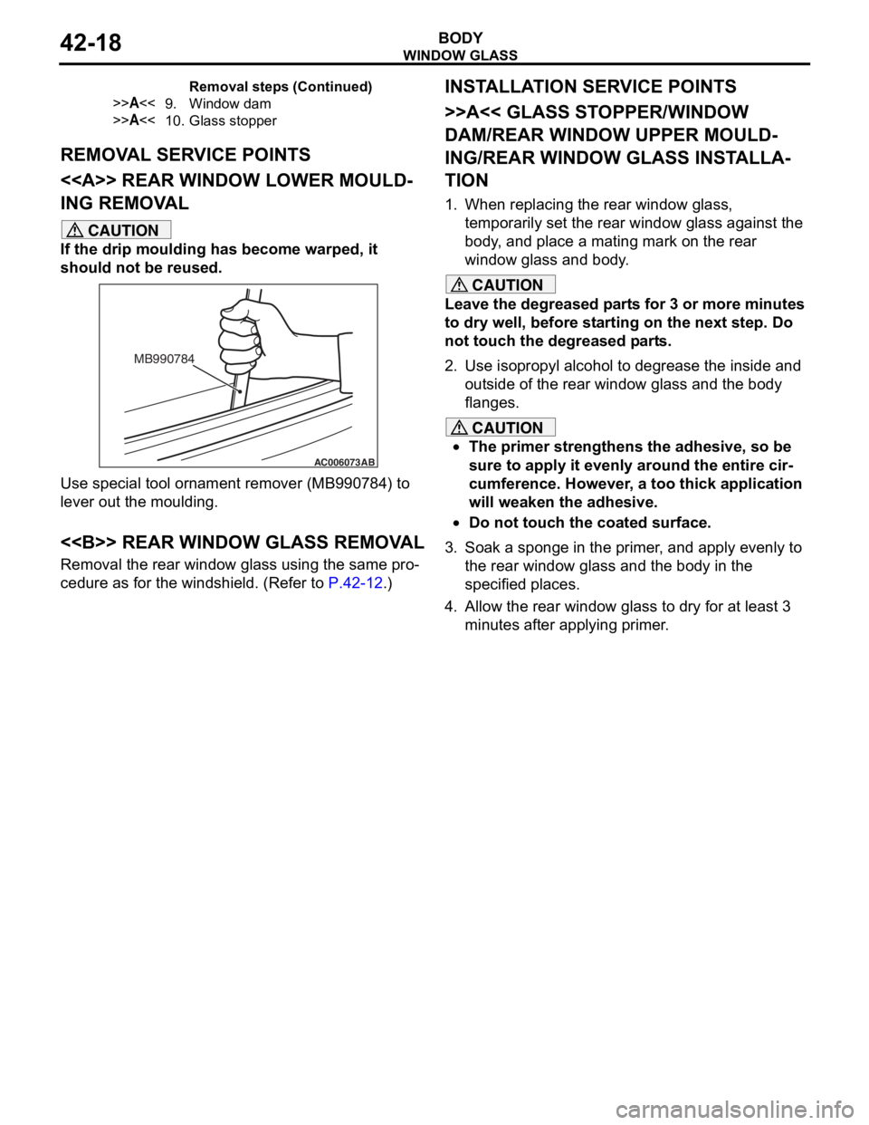
Page 294 of 800
WINDOW GLASS
BODY42-22
INSTALLATION SERVICE POINTS
>>A<< GASKET/CLIP/DUAL LOCK FAS-
TENER INSTALLATION
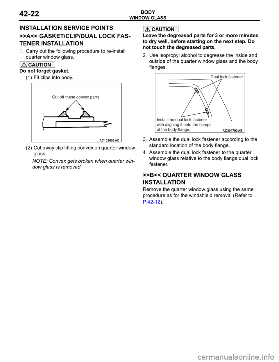
1. Carry out the following procedure to re-install quarter window glass.
CAUTION
Do not forget gasket.
(1) Fit clips into body.
AC103606 AC
Cut off these convex parts
(2) Cut away clip fitting convex on quarter window
glass.
NOTE: Convex gets broken when quarter win-
dow glass is removed.
CAUTION
Leave the degreased parts for 3 or more minutes
to dry well, before starting on the next step. Do
not touch the degreased parts.
2. Use isopropyl alcohol to degrease the inside and
outside of the quarter window glass and the body
flanges.
AC304793AB
Dual lock fastener
Install the dual lock fastener
with aligning it onto the bumps
of the body flange.
3. Assemble the dual lock fastener according to the standard location of the body flange.
4. Assemble the dual lock fastener to the quarter window glass relative to the body flange dual lock
fastener.
>>B<< QUARTER WINDOW GLASS
INSTALLATION
Remove the quarter window glass using the same
procedure as for the windshield removal (Refer to
P.42-12).
Page 296 of 800
Removal steps
1.Connecting the harness connector
<>>>B<<2.Tailgate window glass
>>A<<3.Window lower dam
>>A<<4.Window side dam
>>A<<5.Dual lock fastener
>>A<<6.Glass stopper
>>A<<7.Window spacer
WI ND OW GLAS S
BODY42-24
REMOVA L SER V ICE POINT
<> TA ILGA TE WINDOW GLASS
REMOV
A L
Remove the t a ilgate window g l ass using the same
proce
dure as for th e windshie l d (Refe r to
P.42-12).
INSTALLA T ION SER VICE POINTS
>>A<< WI NDOW SP ACER/GLASS ST OP-
PER/DUAL LOCK FA STENER/WINDOW
DAM INST
ALLA TION
CAUTION
Leave the degreased parts for 3 or more minutes
to dry well, before starting on the next step. Do
not touch the degreased parts.
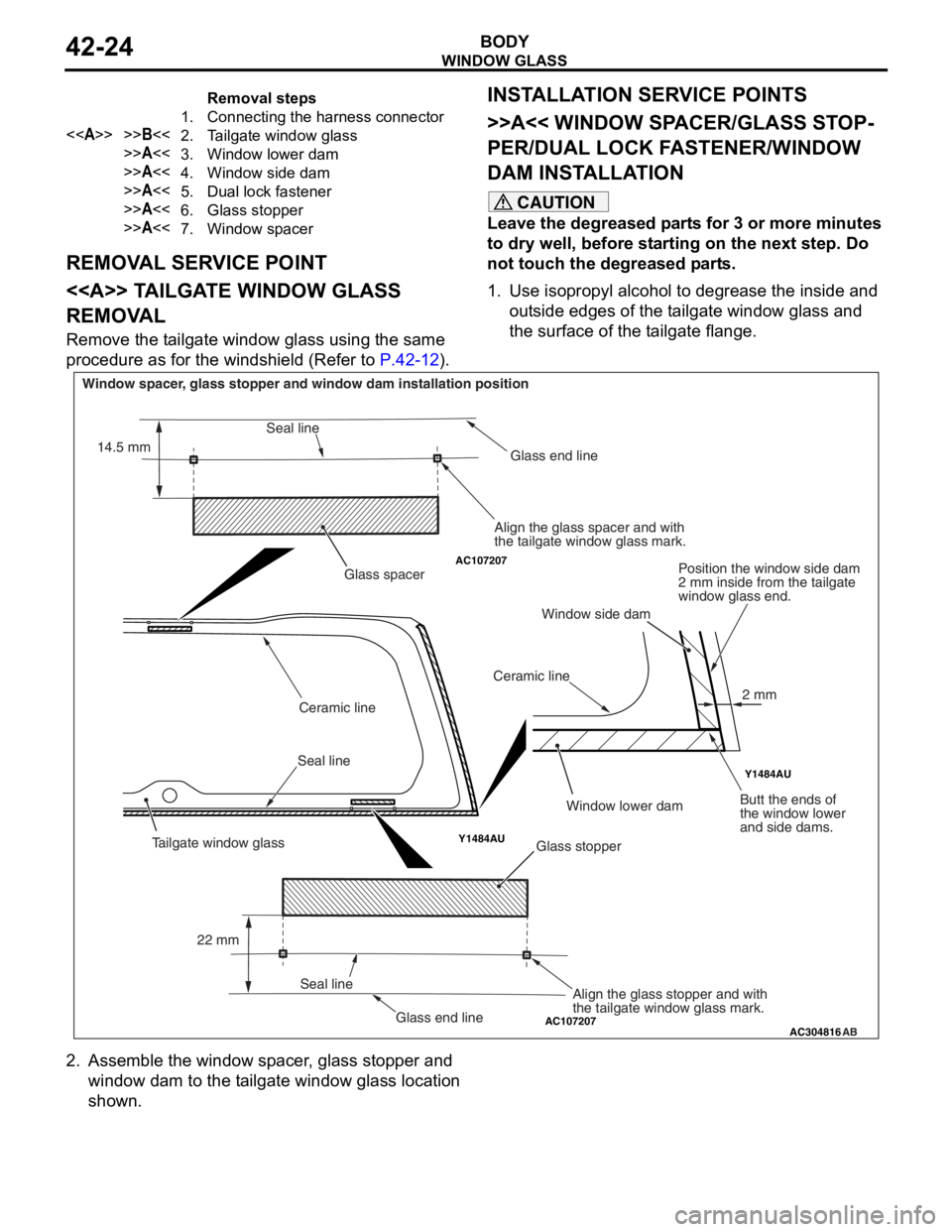
1. Use isopropyl alcohol to degrease the inside and outside edges of the tailgate window glass and
the surface of the tailgate flange.
AC107207
AC107207
Y1484AU Y1484AU
AC304816
AB
Glass stopper
Glass spacer
Seal line Ceramic line
Ceramic lineGlass end line
Glass end line
Window spacer, glass stopper and window dam installation position
Align the glass spacer and with
the tailgate window glass mark.Position the window side dam
2 mm inside from the tailgate
window glass end.
Butt the ends of
the window lower
and side dams.
Align the glass stopper and with
the tailgate window glass mark.
Seal line
Seal line
22 mm
14.5 mm
2 mm
Tailgate window glass
Window lower dam
Window side dam
2. Assemble the window spacer, glass stopper and
window dam to the tailgate window glass location
shown.