aft MITSUBISHI LANCER 2006 Owner's Manual
[x] Cancel search | Manufacturer: MITSUBISHI, Model Year: 2006, Model line: LANCER, Model: MITSUBISHI LANCER 2006Pages: 800, PDF Size: 45.03 MB
Page 95 of 800
IGNITION SYSTEM
ENGINE ELECTRICAL16-33
SPARK PLUG CHECK AND CLEANING
<4G6>
M1163004300353
CAUTION
When pulling off the spark plug cable from the
plug always hold the cable cap, not the cable.
1. Remove the spark plug cables.
2. Remove the spark plugs.
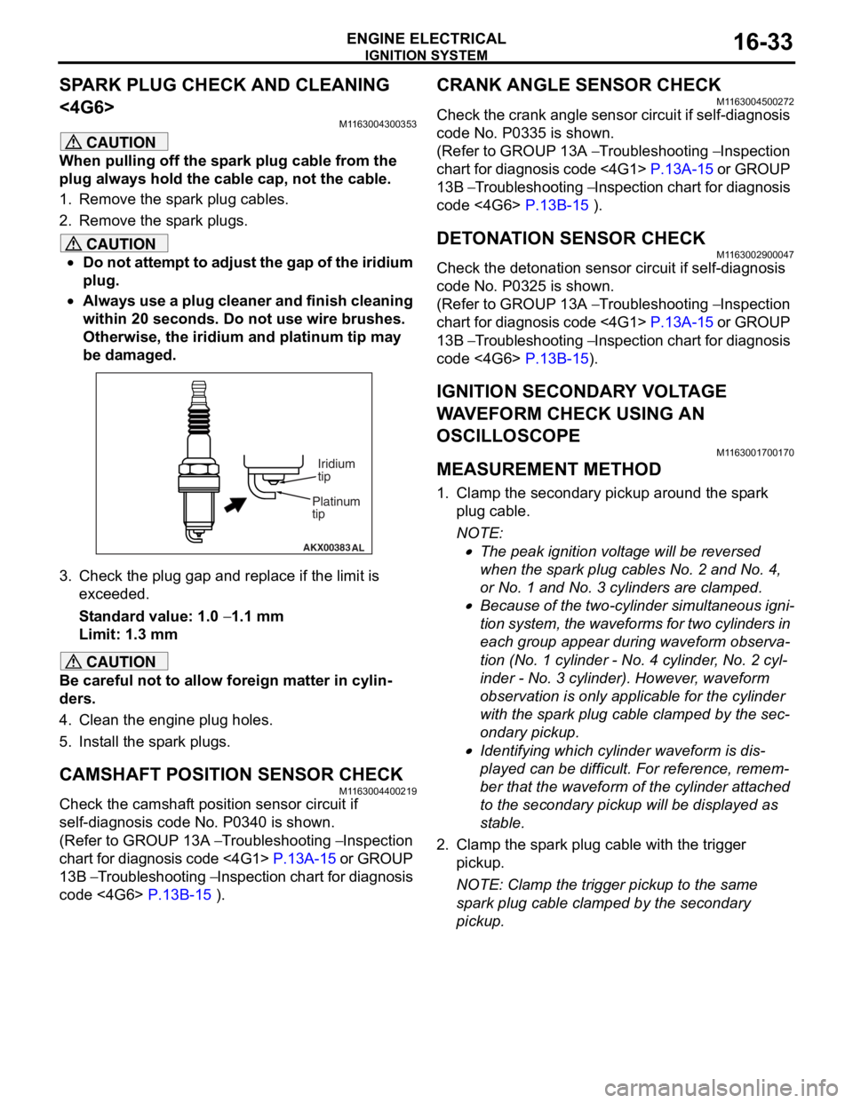
CAUTION
•Do not attempt to adjust the gap of the iridium
plug.
•
AKX00383 AL
Platinum
tipIridium
tip
Always use a plug cleaner and finish cleaning
within 20 seconds. Do not use wire brushes.
Otherwise, the iridium and platinum tip may
be damaged.
3. Check the plug gap and re
place if the limit is
exceeded.
Standard value: 1.0 − 1.1 mm
Limit: 1.3 mm
CAUTION
Be careful not to allow foreign matter in cylin-
ders.
4. Clean the engine plug holes.
5. Install the spark plugs.
CAMSHAFT POSITION SENSOR CHECK
M1163004400219
Check the camshaft position sensor circuit if
self-diagnosis code No. P0340 is shown.
(Refer to GROUP 13A − Troubleshooting − Inspection
chart for diagnosis code <4G1>
P.13A-15 or GROUP
13B − Troubleshooting − Inspection chart for diagnosis
code <4G6>
P.13B-15 ).
CRANK ANGLE SENSOR CHECK
M1163004500272
Check the crank angle sensor circuit if self-diagnosis
code No. P0335 is shown.
(Refer to GROUP 13A − Troubleshooting − Inspection
chart for diagnosis code <4G1>
P.13A-15 or GROUP
13B − Troubleshooting − Inspection chart for diagnosis
code <4G6>
P.13B-15 ).
DETONATION SENSOR CHECKM1163002900047
Check the detonation sensor circuit if self-diagnosis
code No. P0325 is shown.
(Refer to GROUP 13A − Troubleshooting − Inspection
chart for diagnosis code <4G1>
P.13A-15 or GROUP
13B − Troubleshooting − Inspection chart for diagnosis
code <4G6>
P.13B-15).
IGNITION SECONDARY VOLTAGE
WAVEFORM CHECK USING AN
OSCILLOSCOPE
M1163001700170
MEASUREMENT METHOD
1. Clamp the secondary pickup around the spark
plug cable.
NOTE: .
•The peak ignition voltage will be reversed
when the spark plug cables No. 2 and No. 4,
or No. 1 and No. 3 cylinders are clamped.
•Because of the two-cylinder simultaneous igni-
tion system, the waveforms for two cylinders in
each group appear during waveform observa
-
tion (No. 1 cylinder - No. 4 cylinder, No. 2 cyl-
inder - No. 3 cylinder). However, waveform
observation is only applicable for the cylinder
with the spark plug cable clamped by the sec
-
ondary pickup.
•Identifying which cylinder waveform is dis-
played can be difficult. For reference, remem-
ber that the waveform of the cylinder attached
to the secondary pickup will be displayed as
stable.
2. Clamp the spark plug cable with the trigger pickup.
NOTE: Clamp the trigger pickup to the same
spark plug cable clamped by the secondary
pickup.
Page 102 of 800
IGNITION SYSTEM
ENGINE ELECTRICAL16-40
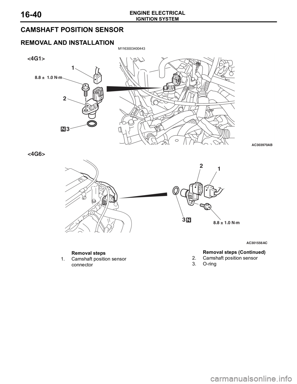
CAMSHAFT POSITION SENSOR
REMOVAL AND INSTALLATION
M1163003400443
AC303970AB
23
8.8 ± 1.0 N·m
N
1
<4G1>
AC301556
N
1
2
3
8.8 ± 1.0 N·m
AC
<4G6>
Removal steps
1.Camshaft position sensor
connector2.Camshaft position sensor
3.O-ring
Removal steps (Continued)
Page 103 of 800
IGNITION SYSTEM
ENGINE ELECTRICAL16-41
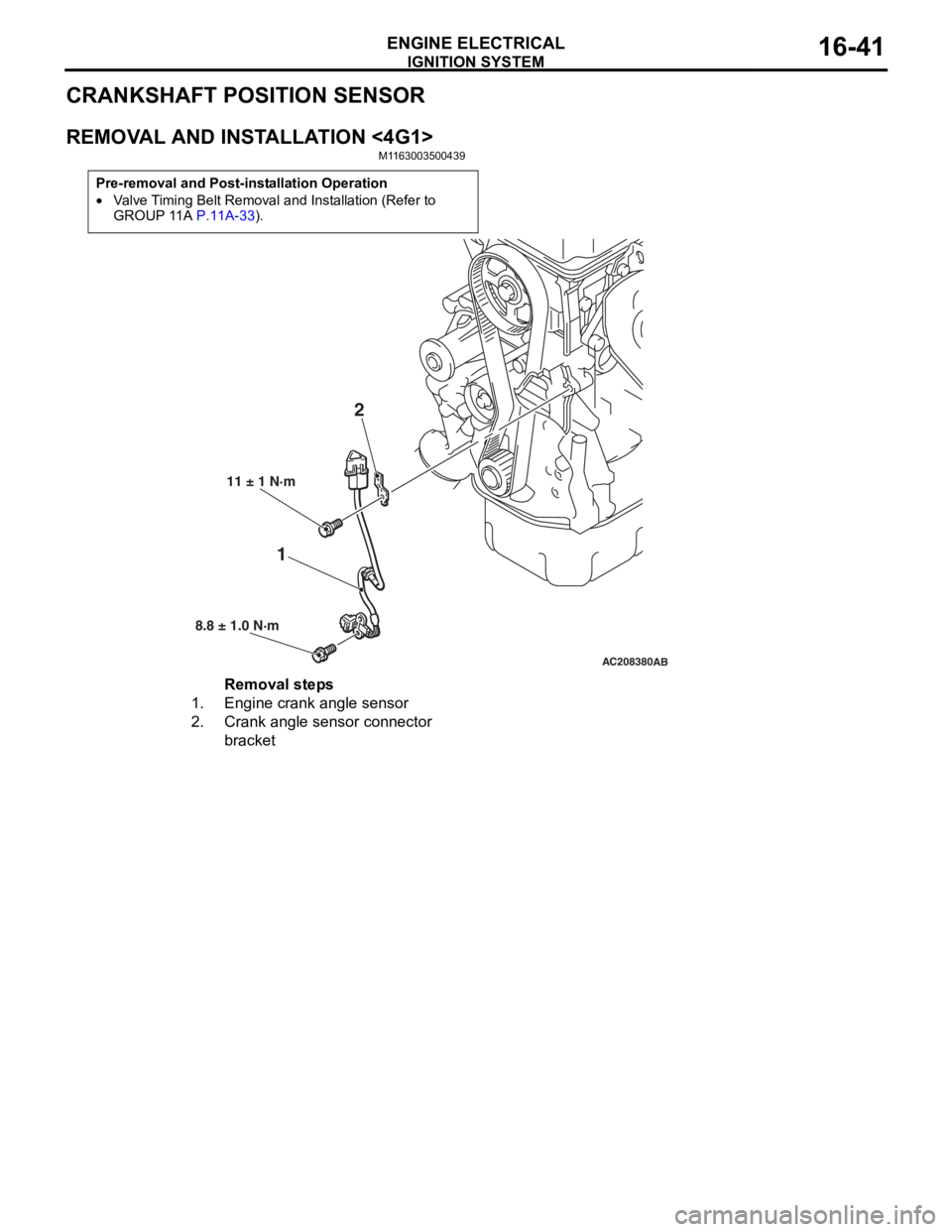
CRANKSHAFT POSITION SENSOR
REMOVAL AND INSTALLATION <4G1>
M1163003500439
Pre-removal and Post-installation Operation
•Valve Timing Belt Removal and Installation (Refer to
GROUP 11A P.11A-33).
AC208380AB
12
11 ± 1 N·m
8.8 ± 1.0 N·m
Removal steps
1.Engine crank angle sensor
2.Crank angle sensor connector
bracket
Page 117 of 800
EMISSION CONTROL
ENGINE AND EMISSION CONTROL17-11
2. Plug the nipple from which the vacuum hose was removed.
3. When the engine is cold or hot, apply a vacuum of 53 kPa, and check the condition of the vacuum.
When engine is cold
(Engine coolant temperature: 40°C or less)
Engine conditionNormal condition
At idleVacuum is maintained.
3,000 r/min
When engine is hot
(Engine coolant temperature: 80°C or higher)
Engine conditionNormal condition
At idleVacuum is maintained.
3,000 r/min (within 3
minutes after engine
starts)Vacuum will leak.
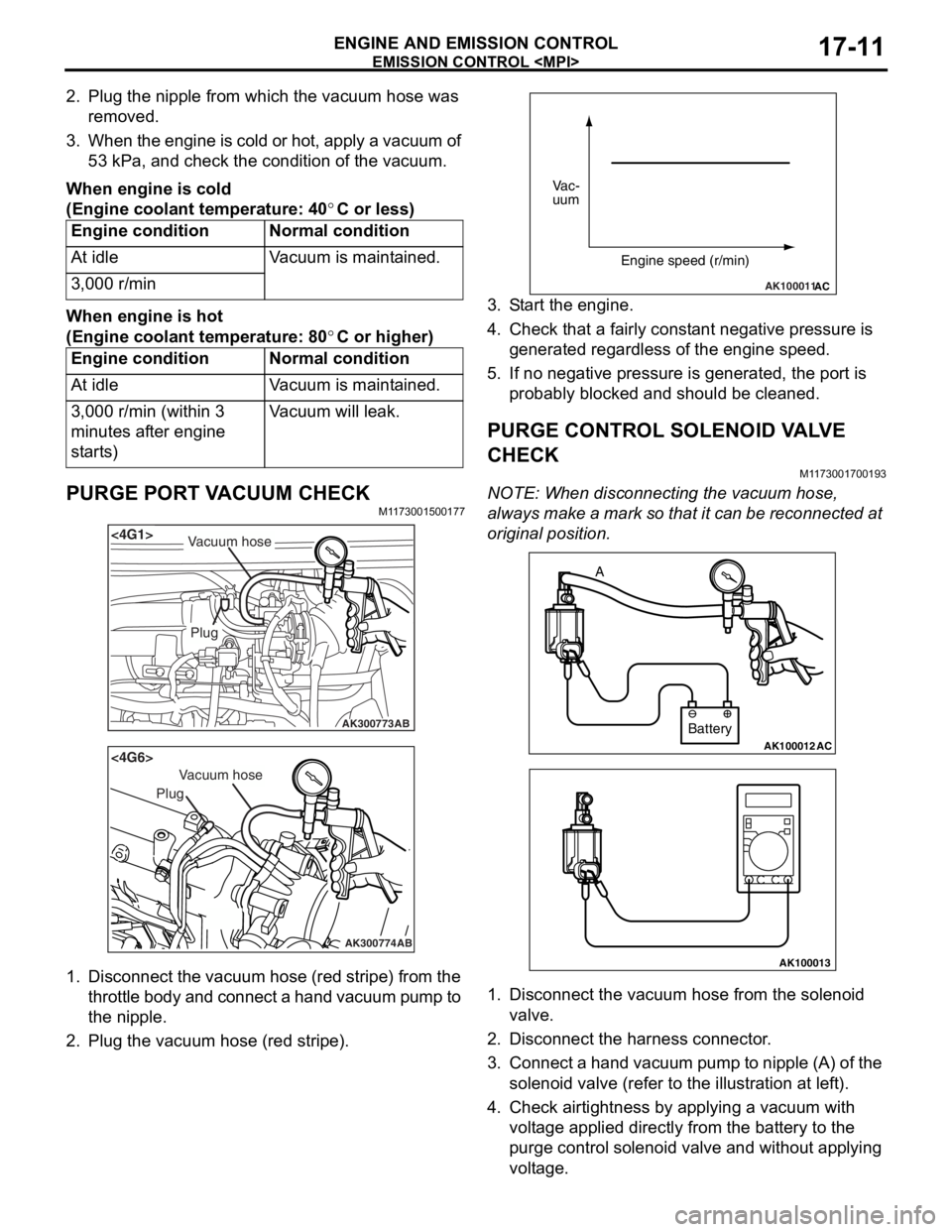
PURGE PORT VACUUM CHECKM1173001500177
AK300773
<4G1>
AB
Plug
Vacuum hose
AK300774
<4G6>
AB
Plug
Vacuum hose
1.Disco nnect th e vacuum ho se (red st ripe) from the
throttle body and connect a hand vacuum pump to
th e nip p le.
2.Plu g the vacuum hose (red stripe).
AK100011AC
Vac-
uum
Engine speed (r/min)
3.S t art the engine.
4.Check t hat a f a irly co nst ant n egative p r essure is
g enerate d regard l ess of the en gine spee d.
5.If no neg ative pressur e is genera t ed, th e port is
p r obably blocked an d sh ould be cleane d.
PURGE CONTROL SOLENOID VA L V E
CHECK
M1173 0017 0019 3
NOTE: Whe n discon nect i ng th e va cuum hose,
always make a mark so th at it can be reconnected at
original p o sition.
AK100012AC
Battery
A
AK100013
1.
Disco nnect the vacu um h o se f r om th e solenoid
valve.
2.Disco nnect the ha rness connector .
3.Con nect a ha nd vacu um pump to nipp le (A) of the
solen o id valve (ref e r to th e ill ust r ation at le f t ).
4.Check a i rtig htness b y app lying a vacuum with
volt age applied d i rectly from t he batt e ry to the
p u rge con t rol so leno id valve an d without app lying
volt age .
Page 133 of 800
26-1
GROUP 26
FRONT AXLE
CONTENTS
GENERAL INFORMATION . . . . . . . .26-2
SERVICE SPECIFICATIONS . . . . . . .26-3
LUBRICANTS . . . . . . . . . . . . . . . . . .26-3
SPECIAL TOOLS . . . . . . . . . . . . . . . .26-4
ON-VEHICLE SERVICE . . . . . . . . . . .26-7
WHEEL BEARING AXIAL PLAY CHECK . . 26-7
HUB BOLT REPLACEMENT . . . . . . . . . . . 26-7
FRONT AXLE HUB ASSEMBLY . . . .26-8
REMOVAL AND INSTALLATION . . . . . . . . 26-8
INSPECTION. . . . . . . . . . . . . . . . . . . . . . . . 26-11
DISASSEMBLY AND REASSEMBLY . . . . . 26-11
INSPECTION. . . . . . . . . . . . . . . . . . . . . . . . 26-13
DRIVESHAFT ASSEMBLY. . . . . . . . .26-14
REMOVAL AND INSTALLATION . . . . . . . . 26-14
DISASSEMBLY AND REASSEMBLY . . . . . 26-18
INSPECTION. . . . . . . . . . . . . . . . . . . . . . . . 26-21
BJ BOOT (RESIN BOOT)
REPLACEMENT . . . . . . . . . . . . . . . . . . . . . 26-21
Page 134 of 800
GENERAL INFORMATION
FRONT AXLE26-2
GENERAL INFORMATION
M1261000100648
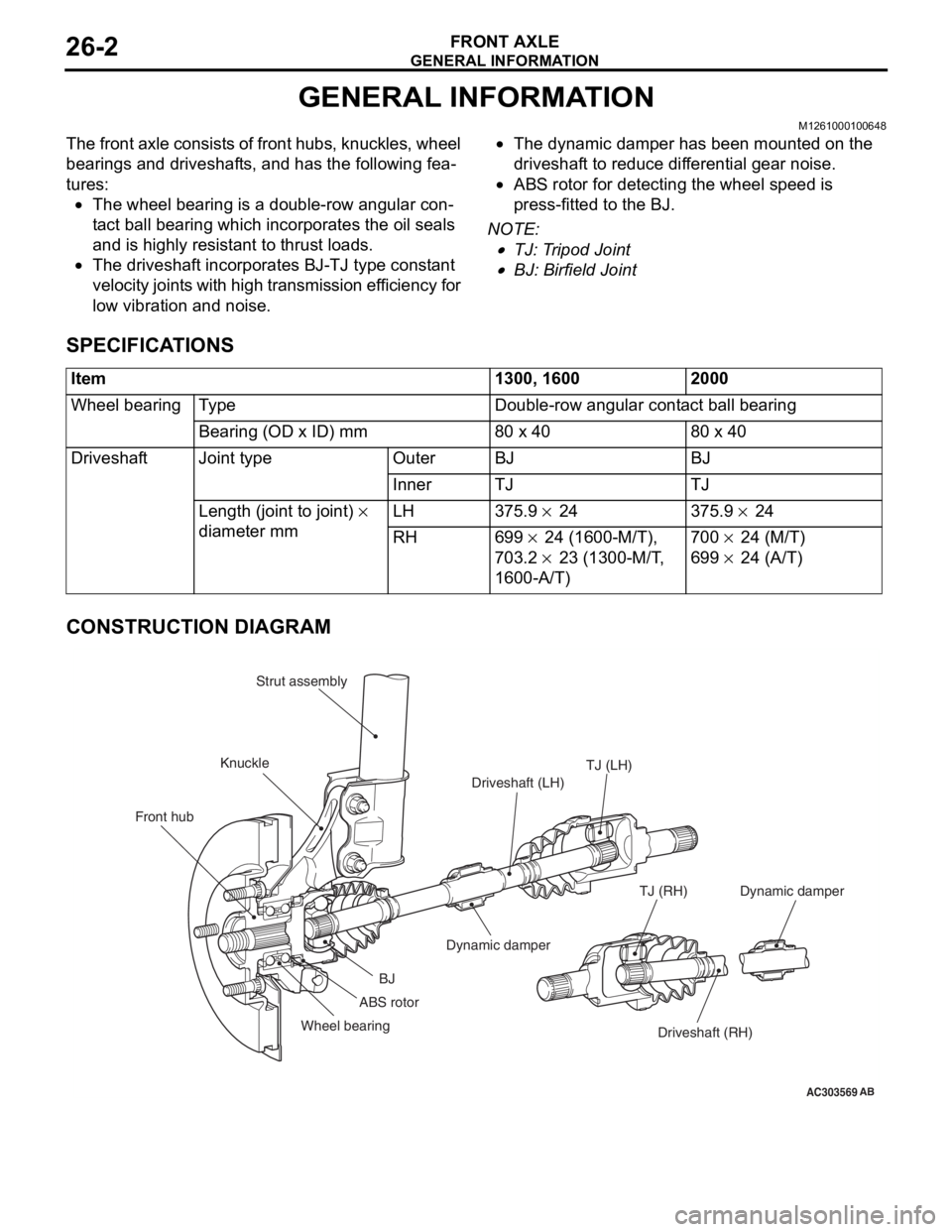
The front axle consists of front hubs, knuckles, wheel
bearings and driveshafts, and has the following fea
-
tures:
•The wheel bearing is a double-row angular con-
tact ball bearing which incorporates the oil seals
and is highly resistant to thrust loads.
•The driveshaft incorporates BJ-TJ type constant
velocity joints with high transmission efficiency for
low vibration and noise.
•The dynamic damper has been mounted on the
driveshaft to reduce differential gear noise.
•ABS rotor for detecting the wheel speed is
press-fitted to the BJ.
NOTE: .
•TJ: Tripod Joint
•BJ: Birfield Joint
SPECIFICATIONS
Item1300, 16002000
Wheel bearingTy p eDouble-row angular contact ball bearing
Bearing (OD x ID) mm80 x 4080 x 40
DriveshaftJoint typeOuterBJBJ
InnerTJTJ
Length (joint to joint) ×
diameter mm LH 375.9 × 24 375.9 × 24
RH699 × 24 (1600-M/T),
703.2
× 23 (1300-M/T,
1600-A/T)
700 × 24 (M/T)
699 × 24 (A/T)
CONSTRUCTION DIAGRAM
AC303569
Front hub KnuckleStrut assembly
TJ (LH)
Driveshaft (LH)
Dynamic damper
BJ
Wheel bearing Driveshaft (RH)
TJ (RH)
AB
ABS rotor
Dynamic damper
Page 136 of 800
SPECIAL TOOLS
FRONT AXLE26-4
SPECIAL TOOLS
M1261000600773
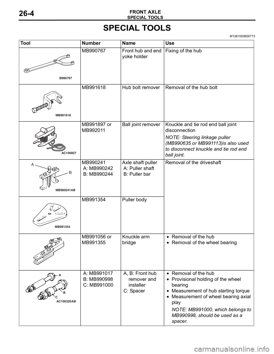
ToolNumberNameUse
B990767
MB990767Fr o n t hu b a n d en d
yoke holderFixing of the h u b
MB991618
MB991618Hub bolt remo verRemoval of the h ub bolt
AC106827
MB991897 or
MB992
01 1Ball j o int remo verKnuckle and tie rod e nd ball joint
discon
nection
NOTE: St eering linkage pu lle r
(MB990 635 or MB991 1 13)is also u s ed
to disconnect kn uckle an d tie rod en d
bal
l j
o
int.
MB990241AB
A BMB990241
A: MB9902 42
B: MB990244
Axle shaft pu ller
A: Puller shaf t
B: Puller bar
Rem o va l of t h e dri v es h a f t
MB991354
MB991354Pulle r body
MB991 056 or
MB991
355Knuckle a r m
bridg
e•Removal of the hu b
•Removal of the whee l bea ring
AC100320 ABA
B
C
A: MB9910 17
B: MB990998
C: MB99100 0
A, B: Fr ont hu b
remover and
ins t all e r
C: Sp acer
•Removal of the hu b
•Prov ision a l ho ldin g of th e wheel
b
earin g
•Measurement of hub st a r ting t o rque
•Measurement of wh eel b earin g axial
pl
a y
NOTE: MB9 91000, which b e lon g s to
MB9909 98, should be used a s a
sp
acer
.
Page 140 of 800
FRONT AXLE HUB ASSEMBLY
FRONT AXLE26-8
FRONT AXLE HUB ASSEMBLY
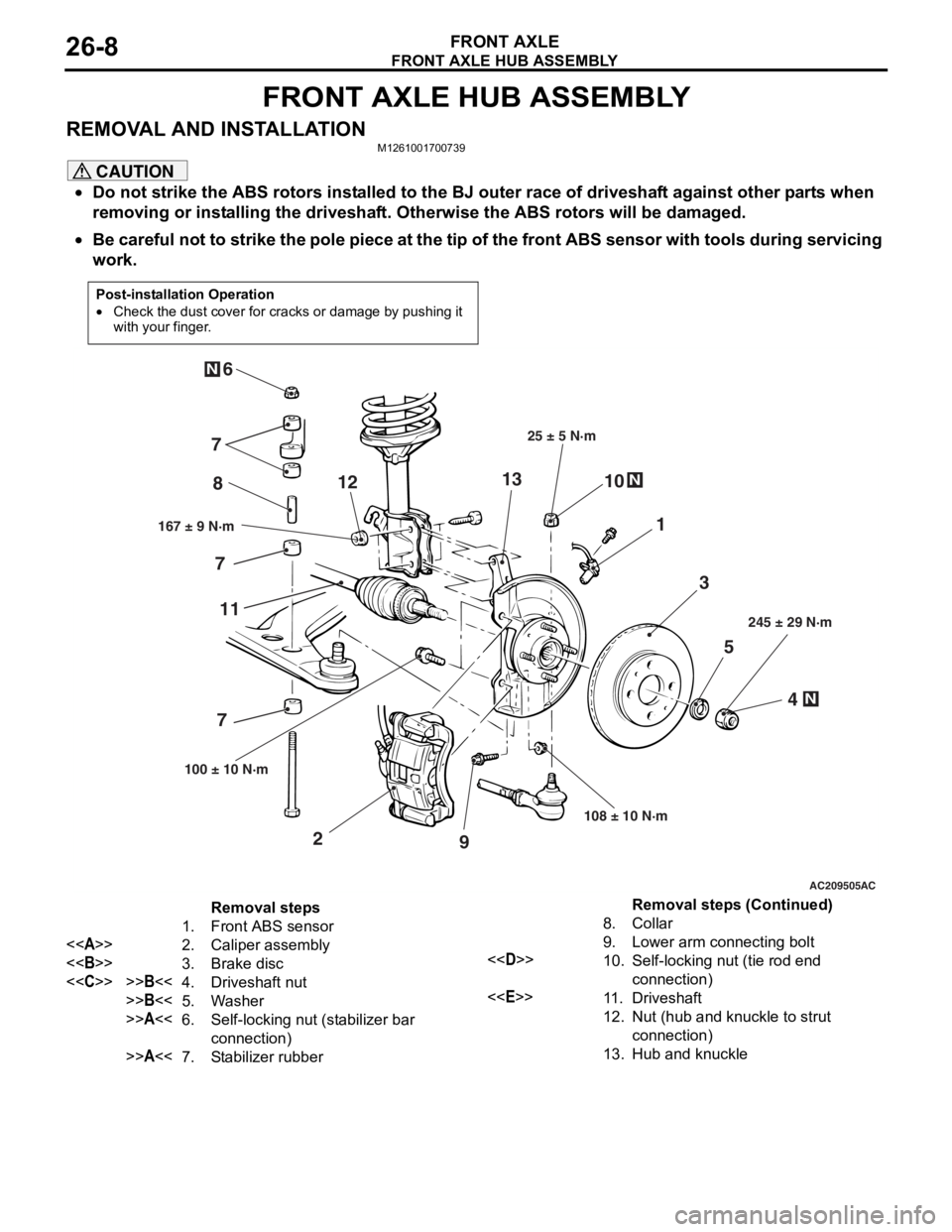
REMOVAL AND INSTALLATIONM1261001700739
CAUTION
•Do not strike the ABS rotors installed to the BJ outer race of driveshaft against other parts when
removing or installing the driveshaft. Otherwise the ABS rotors will be damaged.
•
Post-installation Operation
•Check the dust cover for cracks or damage by pushing it
with your finger.
AC209505
N
N
N
5
4
3
1
8
10
9
2
7
6
167 ± 9 N·m 25 ± 5 N·m
108 ± 10 N·m 245 ± 29 N·m
100 ± 10 N·m
AC
7 7
11 12
13
Removal steps
1. Front ABS sensor
<> 2. Caliper assembly
<> 3. Brake disc
<
>>B<<5. Washer
>>A<<6.Self-locking nut (stabilizer bar
connection)
>>A<<7.Stabilizer rubber
8.Collar
9. Lower arm connecting bolt
<
connection)
<
12.Nut (hub and knuckle to strut
connection)
13.Hub and knuckle
Be careful not to strike the pole piece at the tip of the front ABS sensor with tools during servicing
work.
Removal steps (Continued)
Page 141 of 800
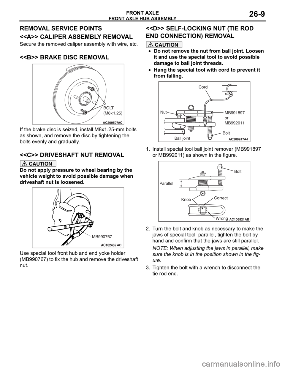
Page 142 of 800
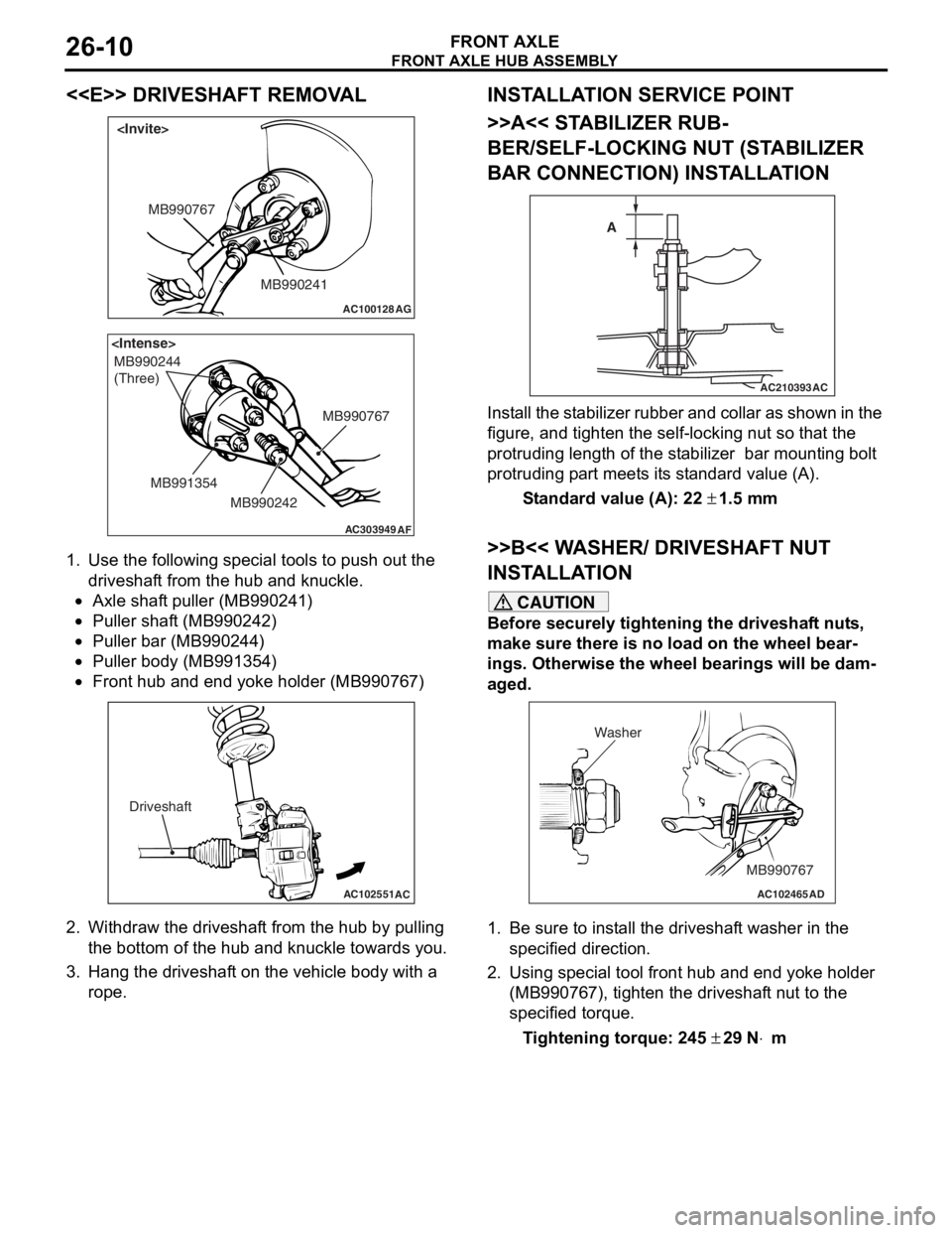
FRONT AXLE HUB ASSEMBLY
FRONT AXLE26-10
<
AC100128
MB990241
MB990767
AG
AC303949
MB990244
(Three)
MB990767
MB990242
MB991354
AF
1.
Use the fo llo wing special to ols to pu sh ou t the
driveshaf t from the hub an d kn uckle.
•Axle shaf t puller (MB9 90241 )
•Puller shaft (MB990 242)
•Puller bar (MB990 244)
•Puller body (MB99135 4)
•
AC102551
AC
Driveshaft
Front hub a nd end yoke holder (MB99076 7)
2.Withdraw th e driveshaf t from the hu b by pulling
th e botto m of the hub and knuckle towards you .
3.Hang the dr ive s haf t on the vehicle b ody with a
rope.
INST ALLA T ION SER VICE POINT
>>A<< STABILIZER RUB-
BER/SELF-LOCKING NUT (ST A BILIZER
BAR CONNECTION) INST
ALLA TION
AC210393AC
A
I
n st a ll the st a b ili zer rubb er an d coll ar as sho w n in t he
figure
, and t i ghte n the self-locking nut so tha t the
protruding length
of the st abilize r bar mount ing b o lt
protruding p
a rt meet s it s st and ard value (A).
St andard va lue (A): 22 ± 1.5 m m
>>B<< W A SHER/ DRIVESHAFT NUT
INST
ALLA TION
CAUTION
Before securely tightening the driveshaft nuts,
make sure there is no load on the wheel bear
-
ings. Otherwise the wheel bearings will be dam-
aged.
AC102465AD
MB990767
Washer
1. Be sure to install the driveshaft washer in the
specified direction.
2. Using special tool front hub and end yoke holder (MB990767), tighten the driveshaft nut to the
specified torque.
Tightening torque: 245 ± 29 N⋅m