aft MITSUBISHI LANCER 2006 Owner's Guide
[x] Cancel search | Manufacturer: MITSUBISHI, Model Year: 2006, Model line: LANCER, Model: MITSUBISHI LANCER 2006Pages: 800, PDF Size: 45.03 MB
Page 146 of 800
DRIVESHAFT ASSEMBLY
FRONT AXLE26-14
DRIVESHAFT ASSEMBLY
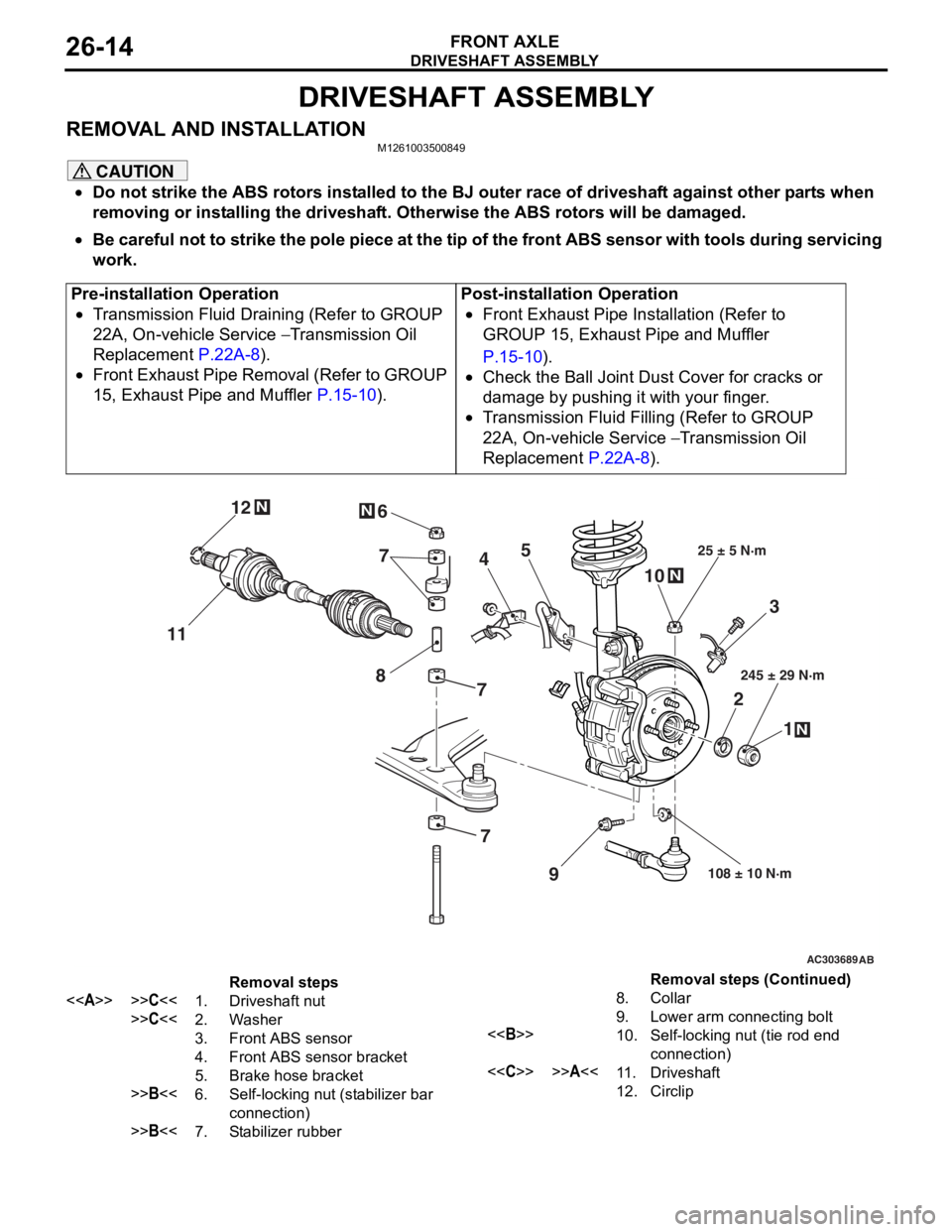
REMOVAL AND INSTALLATIONM1261003500849
CAUTION
•Do not strike the ABS rotors installed to the BJ outer race of driveshaft against other parts when
removing or installing the driveshaft. Otherwise the ABS rotors will be damaged.
•
Pre-installation Operation
•Transmission Fluid Draining (Refer to GROUP
22A, On-vehicle Service
− Transmission Oil
Replacement
P.22A-8).
•Front Exhaust Pipe Removal (Refer to GROUP
15, Exhaust Pipe and Muffler
P.15-10).
Post-installation Operation
•Front Exhaust Pipe Installation (Refer to
GROUP 15, Exhaust Pipe and Muffler
P.15-10).
•Check the Ball Joint Dust Cover for cracks or
damage by pushing it with your finger.
•Transmission Fluid Filling (Refer to GROUP
22A, On-vehicle Service
− Transmission Oil
Replacement
P.22A-8).
AC303689AB
9
N
N
NN
10
7
4
3
2 1
25 ± 5 N·m
245 ± 29 N·m
108 ± 10 N·m
8
5
6
11 12
77
Removal steps
<>>>C<<1.Driveshaft nut
>>C<<2.Washer
3.Front ABS sensor
4.Front ABS sensor bracket
5.Brake hose bracket
>>B<<6.Self-locking nut (stabilizer bar
connection)
>>B<<7.Stabilizer rubber
8.Collar
9.Lower arm connecting bolt
<>10.Self-locking nut (tie rod end
connection)
<
12.Circlip
Be careful not to strike the pole piece at the tip of the front ABS sensor with tools during servicing
work.
Removal steps (Continued)
Page 147 of 800
Page 148 of 800
AC102551AC
Drive shaft
DRIVESHAFT ASSEMBL Y
FRONT AXLE26-16
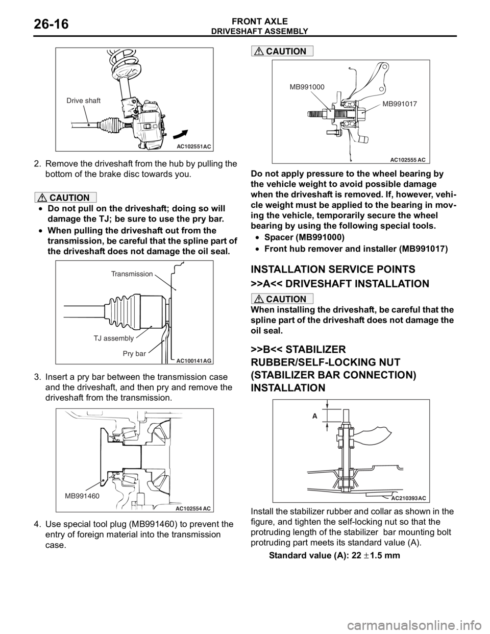
2.Remove th e dr ivesh a f t from th e h ub b y p u lling the
bo ttom of the brake disc toward s you.
CAUTION
•Do not pull on the driveshaft; doing so will
damage the TJ; be sure to use the pry bar.
•
AC100141
Transmission
TJ assembly Pry bar
AG
When pulling the driveshaft out from the
transmission, be careful that the spline part of
the driveshaft does not damage the oil seal.
3. Insert a pry bar between the transmission case and the driveshaft, and then pry and remove the
driveshaft from the transmission.
AC102554
MB991460
AC
4. Use special tool plug (MB991460) to prevent the
entry of foreign material into the transmission
case.
AC102555 AC
MB991017
MB991000
CAUTION
Do not apply pressure to the wheel bearing by
the vehicle weight to avoid possible damage
when the driveshaft is removed. If, however, vehi
-
cle weight must be applied to the bearing in mov-
ing the vehicle, temporarily secure the wheel
bearing by using the following special tools.
•Spacer (MB991000)
•Front hub remover and installer (MB991017)
INSTALLATION SERVICE POINTS
>>A<< DRIVESHAFT INSTALLATION
CAUTION
When installing the driveshaft, be careful that the
spline part of the driveshaft does not damage the
oil seal.
>>B<< STABILIZER
RUBBER/SELF-LOCKING NUT
(STABILIZER BAR CONNECTION)
INSTALLATION
AC210393
AC
A
Install the stabilizer rubber and collar as shown in the
figure, and tighten the self-locking nut so that the
protruding length of the stabilizer bar mounting bolt
protruding part meets its standard value (A).
Standard value (A): 22 ± 1.5 mm
Page 149 of 800

DRIVESHAFT ASSEMBLY
FRONT AXLE26-17
>>C<< WASHER/DRIVESHAFT NUT
INSTALLATION
AC102465AD
MB990767
Washer
1.
Be sure t o inst a ll t he driveshaf t washe r in th e
specifie d dire ctio n.
CAUTION
Before securely tightening the driveshaft nuts,
make sure there is no load on the wheel bear
-
ings. Otherwise the wheel bearing will be dam-
aged.
2. Using special tool front hub and end yoke holder (MB990767), tighten the driveshaft nut to the
specified torque.
Tightening torque: 245 ± 29 N⋅m
Page 150 of 800
DRIVESHAFT ASSEMBLY
FRONT AXLE26-18
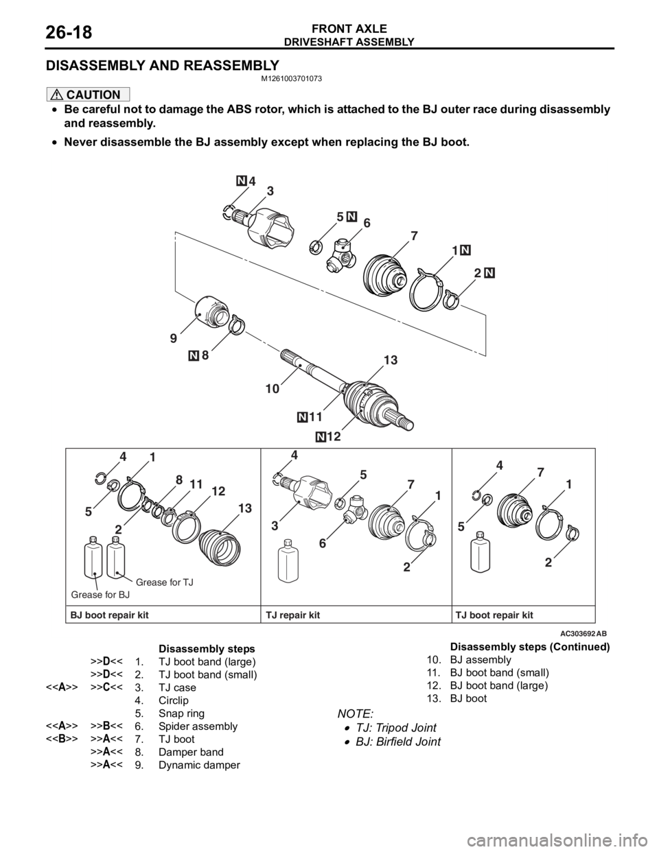
DISASSEMBLY AND REASSEMBLY
M1261003701073
CAUTION
•Be careful not to damage the ABS rotor, which is attached to the BJ outer race during disassembly
and reassembly.
•
AC303692
2
1
4
12
8
11
10
9 7
13
6
5N
N
N
3
N
N
2 1
4
13
8
11
12
5
21
4
7
6 5
3 21
4
7
5
AB
N
N
BJ boot repair kit TJ boot repair kit
TJ repair kit
Grease for TJ
Grease for BJ
Disassembly steps
>>D<<1.TJ boot band (large)
>>D<<2.TJ boot band (small)
<>>>C<<3.TJ case
4.Circlip
5.Snap ring
<>>>B<<6.Spider assembly
<>>>A<<7.TJ boot
>>A<<8.Damper band
>>A<<9.Dynamic damper
10.BJ assembly
11 .BJ boot band (small)
12.BJ boot band (large)
13.BJ boot
Never disassemble the BJ assembly except when replacing the BJ boot.
NOTE: .
•TJ: Tripod Joint
•BJ: Birfield Joint
Disassembly steps (Continued)
Page 151 of 800
DRIVESHAFT ASSEMBLY
FRONT AXLE26-19
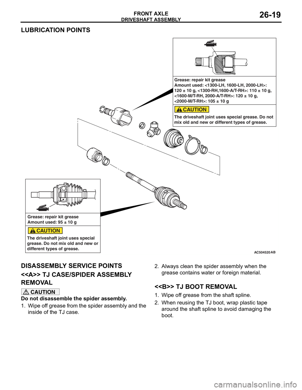
LUBRICATION POINTS
AC504520AB
Grease: repair kit grease
Amount used: 95 ± 10 g
The driveshaft joint uses special
grease. Do not mix old and new or
different types of grease.
CAUTION
Grease: repair kit grease
Amount used: <1300-LH, 1600-LH, 2000-LH>:
120 ± 10 g, <1300-RH,1600-A/T-RH>: 110 ± 10 g,
<1600-M/T-RH, 2000-A/T-RH>: 120 ± 10 g,
<2000-M/T-RH>: 105 ± 10 g
The driveshaft joint uses special grease. Do not
mix old and new or different types of grease.
CAUTION
DISASSEMBL Y SER V ICE POINTS
<> TJ CASE/SPIDER ASSEMBL Y
REMOV
A L
CAUTION
Do not disassemble the spider assembly.
1. Wipe off grease from the spider assembly and the inside of the TJ case.
2. Always clean the spider assembly when the
grease contains water or foreign material.
<> TJ BOOT REMOVAL
1. Wipe off grease from the shaft spline.
2. When reusing the TJ boot, wrap plastic tape around the shaft spline to avoid damaging the
boot.
Page 152 of 800
DRIVESHAFT ASSEMBLY
FRONT AXLE26-20
REASSEMBLY SERVICE POINTS
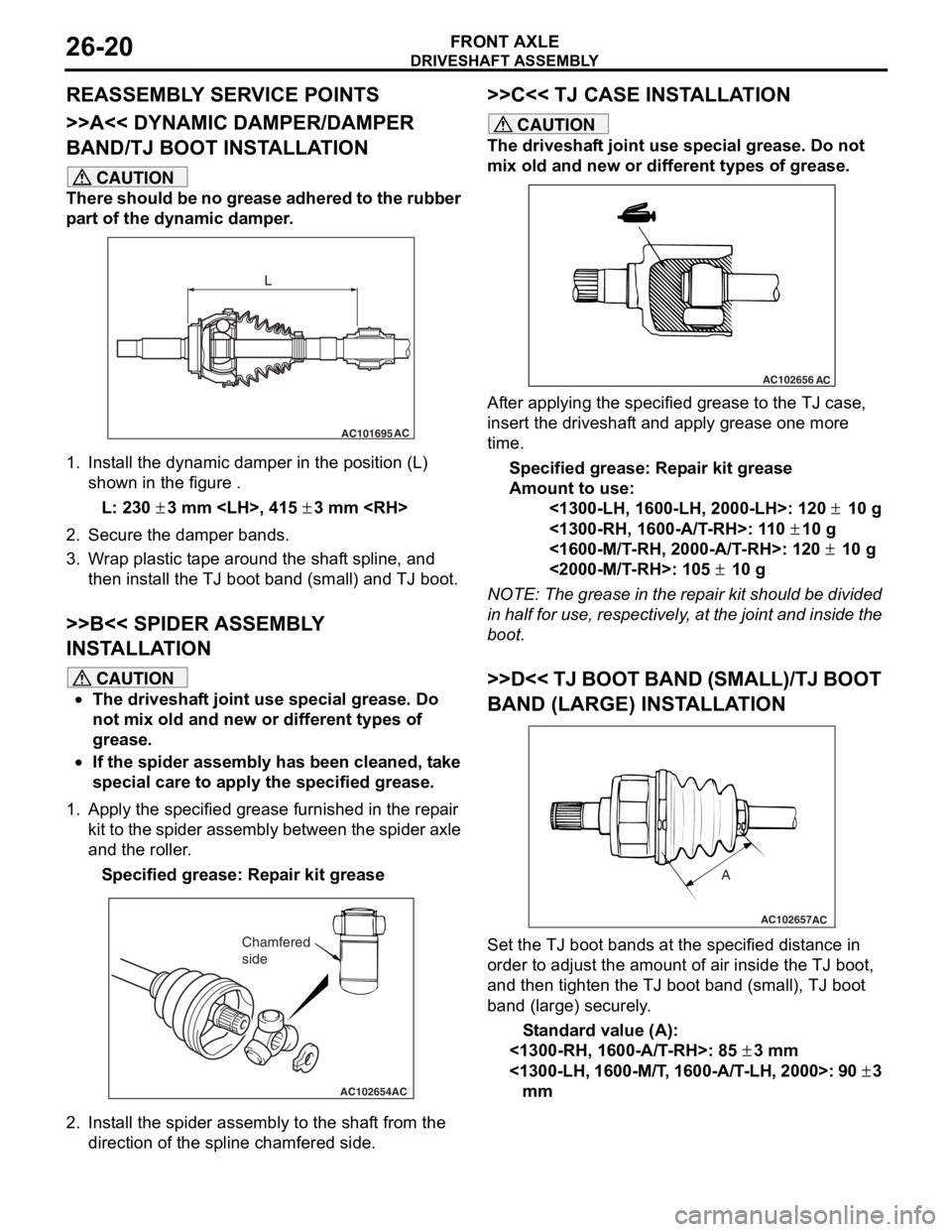
>>A<< DYNAMIC DAMPER/DAMPER
BAND/TJ BOOT INSTALLATION
CAUTION
There should be no grease adhered to the rubber
part of the dynamic damper.
AC101695AC
L
1. Install the dynamic damper in the position (L)
shown in the figure .
L: 230 ± 3 mm
2. Secure the damper bands.
3. Wrap plastic tape around the shaft spline, and then install the TJ boot band (small) and TJ boot.
>>B<< SPIDER ASSEMBLY
INSTALLATION
CAUTION
•The driveshaft joint use special grease. Do
not mix old and new or different types of
grease.
•If the spider assembly has been cleaned, take
special care to apply the specified grease.
1. Apply the specified grease furnished in the repair kit to the spider assembly between the spider axle
and the roller.
Specified grease: Repair kit grease
AC102654AC
Chamfered
side
2. Install the spider assembly to the shaft from the direction of the spline chamfered side.
>>C<< TJ CASE INSTALLATION
CAUTION
The driveshaft joint use special grease. Do not
mix old and new or different types of grease.
AC102656AC
After applying the specified grease to the TJ case,
insert the driveshaft and apply grease one more
time.
Specified grease: Repair kit grease
Amount to use:
<1300-LH, 1600-LH, 2000-LH>: 120 ± 10 g
<1300-RH, 1600-A/T-RH>: 110 ± 10 g
<1600-M/T-RH, 2000-A/T-RH>: 120 ± 10 g
<2000-M/T-RH>: 105 ± 10 g
NOTE: The grease in the repair kit should be divided
in half for use, respectively, at the joint and inside the
boot.
>>D<< TJ BOOT BAND (SMALL)/TJ BOOT
BAND (LARGE) INSTALLATION
AC102657
A
AC
Set the TJ boot bands at the specified distance in
order to adjust the amount of air inside the TJ boot,
and then tighten the TJ boot band (small), TJ boot
band (large) securely.
Standard value (A):
<1300-RH, 1600-A/T-RH>: 85 ± 3 mm
<1300-LH, 1600-M/T, 1600-A/T-LH, 2000>: 90 ± 3
mm
Page 153 of 800
DRIVESHAFT ASSEMBLY
FRONT AXLE26-21
INSPECTION
M1261003800130
•Check the driveshaft for damage, bending or cor-
rosion.
•Check the driveshaft spline part for wear or dam-
age.
•Check the spider assembly for roller rotation,
wear or corrosion.
•Check the groove inside TJ case for wear or cor-
rosion.
•Check the dynamic damper for damage or crack-
ing.
•Check the boots for deterioration, damage or
cracking.
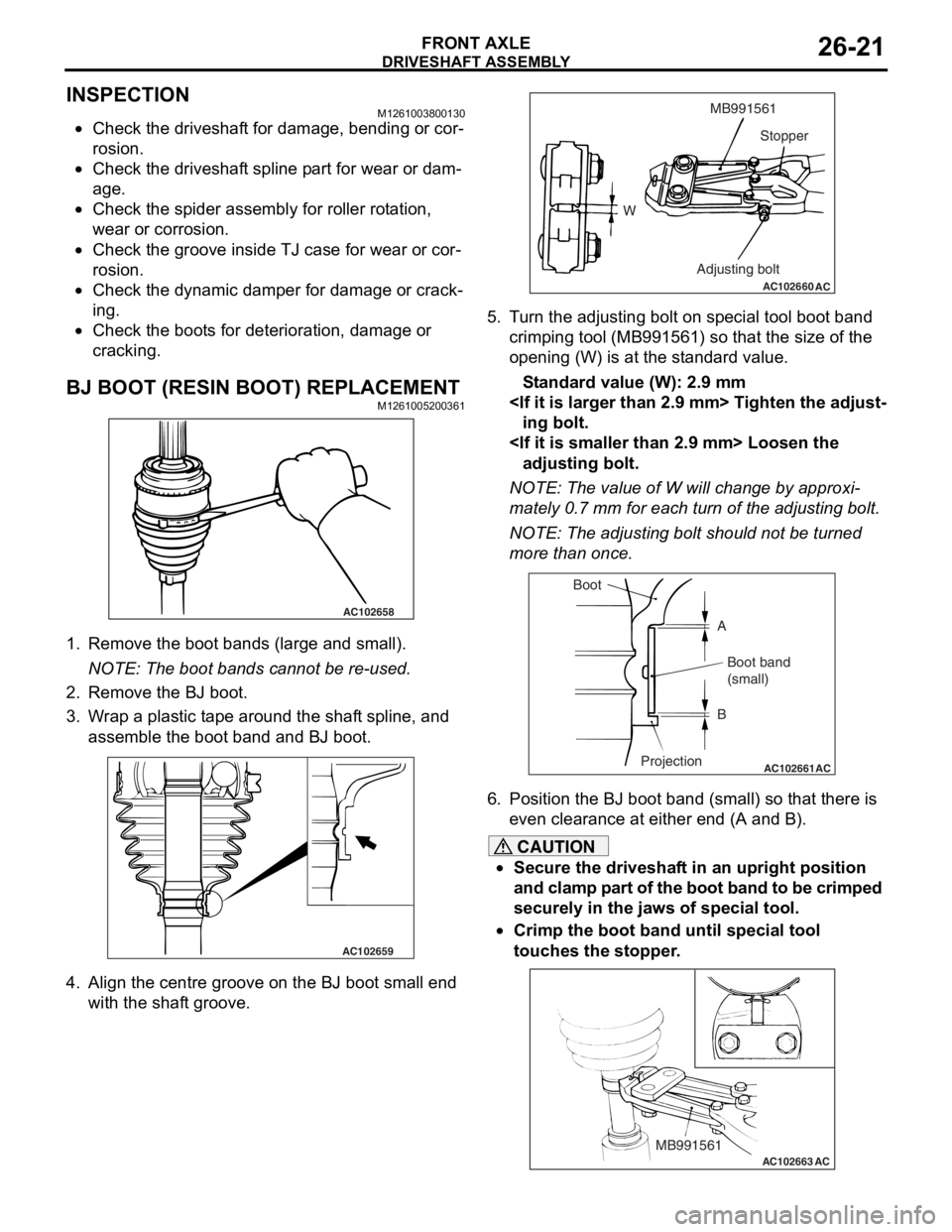
BJ BOOT (RESIN BOOT) REPLACEMENTM1261005200361
AC102658
1.Remove the bo ot ban ds (large a nd small).
NOTE: The boot ba nds canno t be re -used .
2.Remove the BJ boot.
3.W r ap a plastic t a pe arou nd the shaf t spline, an d
asse mble the b oot ba nd and BJ boo t.
AC102659
4.Align th e ce ntre gro o ve o n the BJ boot small end
wit h the shaf t groo ve.
AC102660
WMB991561
Stopper
Adjusting bolt
AC
5. T u rn the ad justing bolt o n sp ecial too l boo t band
crimping tool (MB9915 61) so that the size of the
o penin g (W) is at t he st and ard value .
St andard va lue (W): 2 . 9 mm
ing bolt.
adjustin g bolt.
NOTE: The value of W will chang e by approxi-
mately 0.7 mm for ea ch tu rn of th e adjusting bolt.
NOTE: The ad justing bolt shou ld no t be tu rned
more th an once.
AC102661AC
Boot
ABoot band
(small)
B
Projection
6. Position the BJ boo t band (small) so th at there is
e v en clea rance at either en d (A and B).
CAUTION
•Secure the driveshaft in an upright position
and clamp part of the boot band to be crimped
securely in the jaws of special tool.
•
AC102663 ACMB991561
Crimp the boot band until special tool
touches the stopper.
Page 154 of 800
DRIVESHAFT ASSEMBLY
FRONT AXLE26-22
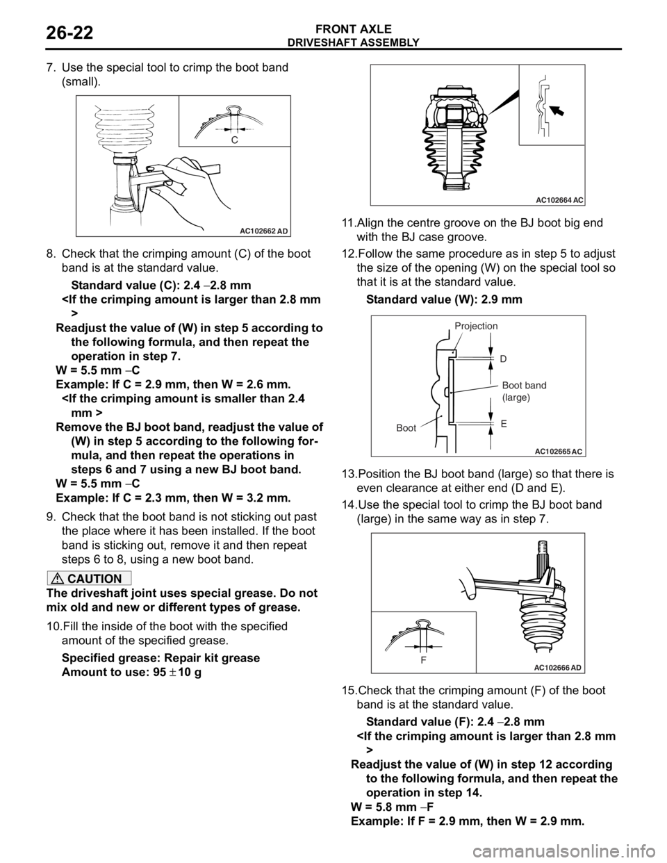
7. Use the special tool to crimp the boot band (small).
AC102662
C
AD
8.Check t hat the crimpin g amount (C) of the bo ot
ba nd is at th e st and ard value.
St andard va lue (C): 2.4 − 2.8 mm
Readjust th e value of (W) in s t ep 5 acc ord i ng to
the following fo rm ula, and then repea t the
operation in step 7.
W = 5.5 mm − C
Example : If C = 2.9 mm, the n W = 2.6 mm.
Rem o v e the BJ bo ot ba nd , re ad ju st the v a l ue of
(W) in ste p 5 acc ord i ng to the following for
-
mula, and then repe at the o perations i n
step
s 6 and 7 using a new BJ boot band .
W = 5.5 mm − C
Example : If C = 2.3 mm, the n W = 3.2 mm.
9.Check t hat the boot b and is no t sticking o u t p a st
th e pla c e wher e it h a s be en in st alled. If t he boo t
ba nd is st icking out, remove it a nd the n repea t
step s 6 to 8, u s in g a new b oot ban d.
CAUTION
The driveshaft joint uses special grease. Do not
mix old and new or different types of grease.
10.Fill the inside of the boot with the specified amount of the specified grease.
Specified grease: Repair kit grease
Amount to use: 95 ± 10 g
AC102664AC
11.Align the centre groove on the BJ boot big end with the BJ case groove.
12.Follow the same procedure as in step 5 to adjust
the size of the opening (W) on the special tool so
that it is at the standard value.
Standard value (W): 2.9 mm
AC102665 AC
Boot Projection
Boot band
(large)
D
E
13.Position the BJ boot band (large) so that there is even clearance at either end (D and E).
14.Use the special tool to crimp the BJ boot band
(large) in the same way as in step 7.
AC102666FAD
15.Check that the crimping amount (F) of the boot band is at the standard value.
Standard value (F): 2.4 − 2.8 mm
Readjust the value of (W) in step 12 according to the following formula, and then repeat the
operation in step 14.
W = 5.8 mm − F
Example: If F = 2.9 mm, then W = 2.9 mm.
Page 155 of 800
DRIVESHAFT ASSEMBLY
FRONT AXLE26-23
Remove the BJ boot band, readjust the value of
(W) in step 12 according to the following for
-
mula, and then repeat the operations in
steps 13 and 14 using a new BJ boot band.
W = 5.8 mm − F
Example: If F = 2.3 mm, then W = 3.5 mm.
16.Check that the boot band is not sticking out past
the place where it has been installed. If the boot
band is sticking out, remove it and then repeat
steps 13 to 15, using a new boot band.