body MITSUBISHI LANCER 2006 Owner's Manual
[x] Cancel search | Manufacturer: MITSUBISHI, Model Year: 2006, Model line: LANCER, Model: MITSUBISHI LANCER 2006Pages: 800, PDF Size: 45.03 MB
Page 142 of 800
FRONT AXLE HUB ASSEMBLY
FRONT AXLE26-10
<
AC100128
MB990241
MB990767
AG
AC303949
MB990244
(Three)
MB990767
MB990242
MB991354
AF
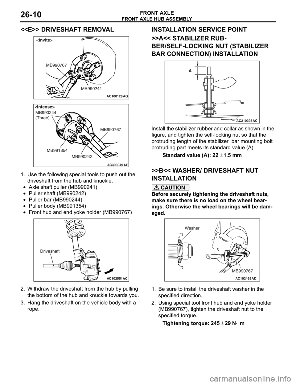
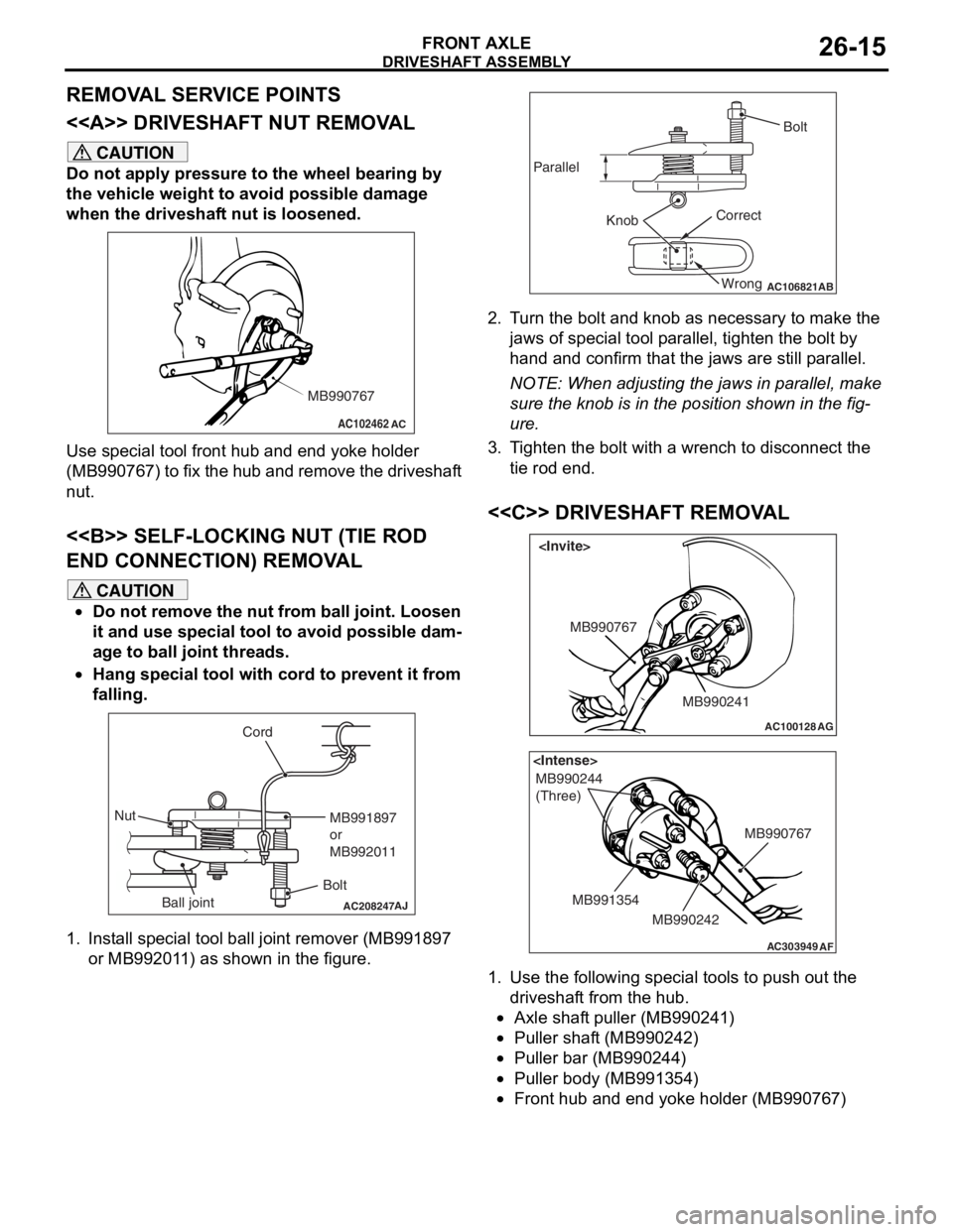
1.
Use the fo llo wing special to ols to pu sh ou t the
driveshaf t from the hub an d kn uckle.
•Axle shaf t puller (MB9 90241 )
•Puller shaft (MB990 242)
•Puller bar (MB990 244)
•Puller body (MB99135 4)
•
AC102551
AC
Driveshaft
Front hub a nd end yoke holder (MB99076 7)
2.Withdraw th e driveshaf t from the hu b by pulling
th e botto m of the hub and knuckle towards you .
3.Hang the dr ive s haf t on the vehicle b ody with a
rope.
INST ALLA T ION SER VICE POINT
>>A<< STABILIZER RUB-
BER/SELF-LOCKING NUT (ST A BILIZER
BAR CONNECTION) INST
ALLA TION
AC210393AC
A
I
n st a ll the st a b ili zer rubb er an d coll ar as sho w n in t he
figure
, and t i ghte n the self-locking nut so tha t the
protruding length
of the st abilize r bar mount ing b o lt
protruding p
a rt meet s it s st and ard value (A).
St andard va lue (A): 22 ± 1.5 m m
>>B<< W A SHER/ DRIVESHAFT NUT
INST
ALLA TION
CAUTION
Before securely tightening the driveshaft nuts,
make sure there is no load on the wheel bear
-
ings. Otherwise the wheel bearings will be dam-
aged.
AC102465AD
MB990767
Washer
1. Be sure to install the driveshaft washer in the
specified direction.
2. Using special tool front hub and end yoke holder (MB990767), tighten the driveshaft nut to the
specified torque.
Tightening torque: 245 ± 29 N⋅m
Page 147 of 800
Page 166 of 800
TROUBLESHOOTING
WHEEL AND TYRE31-4
WHEEL BALANCE ACCURACY
M1311001700247
PURPOSE
This section contains tips and procedures for achiev-
ing accurate wheel balance. Steering wheel vibration
and/or body shake can result if any of these proce
-
dures are not carefully observed.
1. Wheels and tyres must be properly mounted on a balancer in order to achieve correct balance.
Centring the wheel on the shaft of the balancer is
essential for proper mounting.
2. Off-the-car wheel balancers must be calibrated periodically to ensure good balancing results. An
inaccurately calibrated balancer could cause
unnecessary replacement of tyres, shocks,
suspension components, or steering components.
Check your balancer's calibration approximately
every 100 balances. Your wheel balancer's instruc
-
tion manual should include calibration procedures. If
the calibration procedures specifically for your bal
-
ancer are missing, use the generic steps in this sec-
tion for zero calibration, static balance, and dynamic
balance checks. The wheel balancer calibration
checks are also described in the flowchart. (Refer to
P.31-6).
PROCEDURE
1. Confirm that the balancer's cone and the wheel
mounting cone are undamaged and free of dirt
and rust.
2. On this vehicle, the wheel's centre hole on the hub side has a chamfered edge. Use a
back-mounting cone on your wheel balancer to
centre the wheel on the balancer shaft.
3. Install a wheel mounting cone. The appropriate size cone for this vehicle is 67.0 mm.
4. Before balancing the wheel, remove any wheel weights from both sides. Also check both sides for
any damage.
5. When installing wheel weights, hammer them at a straight (not diagonal) angle.
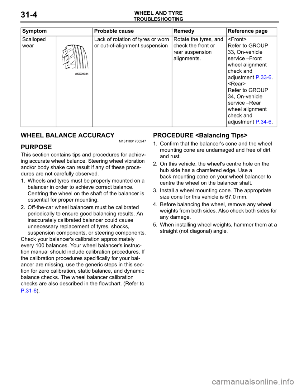
Scalloped
wear
ACX00934
Lack of rot a tio n of tyres or worn
or out-of-a
lign m ent suspensionRota te th e tyre s, an d
check the f
r ont or
rea
r suspension
alignment
s.
Refer to GROUP
33
, On -vehicle
serv
ic e
− Front
whee
l alignment
check and
ad
justmen t
P.33-6.
Refer to GROUP
34
, On -vehicle
serv
ic e
− Rear
whee
l alignment
check and
ad
justmen t
P.34-6.
Sy mptom P robable cause Reme dy Referen ce p a g e
Page 174 of 800
ENGINE MOUNTING
POWER PLANT MOUNT32-4
ENGINE MOUNTING
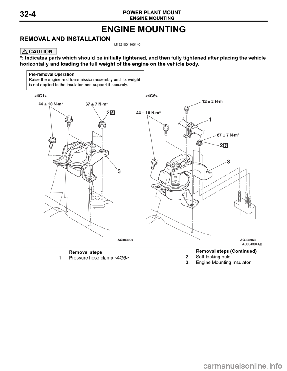
REMOVAL AND INSTALLATIONM1321001100440
CAUTION
*: Indicates parts which should be initially tightened, and then fully tightened after placing the vehicle
horizontally and loading the full weight of the engine on the vehicle body.
Pre-removal Operation
Raise the engine and transmission assembly until its weight
is not applied to the insulator, and support it securely.
AC303999AC303968AC304304AB
<4G1> <4G6>
44 ± 10 N·m* 67 ± 7 N·m*
2N
3
44 ± 10 N·m*
67 ± 7 N·m*
2N
3
12 ± 2 N·m
1
Removal steps
1.Pressure hose clamp <4G6>2.Self-locking nuts
3.Engine Mounting Insulator
Removal steps (Continued)
Page 175 of 800
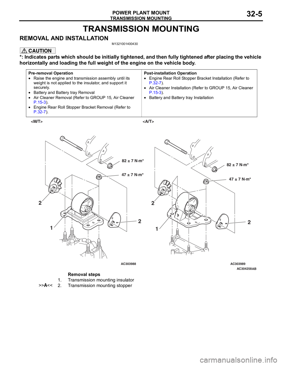
TRANSMISSION MOUNTING
POWER PLANT MOUNT32-5
TRANSMISSION MOUNTING
REMOVAL AND INSTALLATIONM1321001400430
CAUTION
*: Indicates parts which should be initially tightened, and then fully tightened after placing the vehicle
horizontally and loading the full weight of the engine on the vehicle body.
Pre-removal Operation
•Raise the engine and transmission assembly until its
weight is not applied to the insulator, and support it
securely.
•Battery and Battery tray Removal
•Air Cleaner Removal (Refer to GROUP 15, Air Cleaner
P.15-3).
•Engine Rear Roll Stopper Bracket Removal (Refer to
P.32-7).
Post-installation Operation
•Engine Rear Roll Stopper Bracket Installation (Refer to
P.32-7).
•Air Cleaner Installation (Refer to GROUP 15, Air Cleaner
P.15-3).
•Battery and Battery tray Installation
AC303988AC303989AC304258
AB
82 ± 7 N·m*
47 ± 7 N·m*82 ± 7 N·m*
47 ± 7 N·m*
1 1
2
22
2
Removal steps
1.Transmission mounting insulator
>>A<<2.Transmission mounting stopper
Page 177 of 800
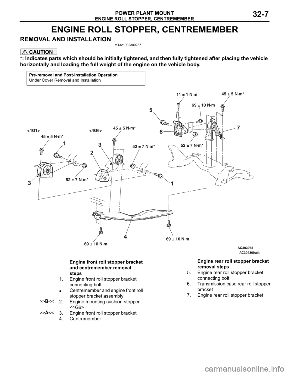
ENGINE ROLL STOPPER, CENTREMEMBER
POWER PLANT MOUNT32-7
ENGINE ROLL STOPPER, CENTREMEMBER
REMOVAL AND INSTALLATIONM1321002300287
CAUTION
*: Indicates parts which should be initially tightened, and then fully tightened after placing the vehicle
horizontally and loading the full weight of the engine on the vehicle body.
Pre-removal and Post-installation Operation
Under Cover Removal and Installation
AC303978
AC304309
45 ± 5 N·m*45 ± 5 N·m*
<4G1> <4G6>
52 ± 7 N·m* 52 ± 7 N·m*
45 ± 5 N·m*
52 ± 7 N·m*
11 ± 1 N·m
69 ± 10 N·m
69 ± 10 N·m 69 ± 10 N·m
1
3 2
1
3
4
56 7
AB
Engine front roll stopper bracket
and centremember removal
steps
1.Engine front roll stopper bracket
connecting bolt
•Centremember and engine front roll
stopper bracket assembly
>>B<<2.Engine mounting cushion stopper
<4G6>
>>A<<3.Engine front roll stopper bracket
4.Centremember
Engine rear roll stopper bracket
removal steps
5.Engine rear roll stopper bracket
connecting bolt
6.Transmission case rear roll stopper
bracket
7.Engine rear roll stopper bracket
Page 178 of 800
CROSSMEMBER
POWER PLANT MOUNT32-8
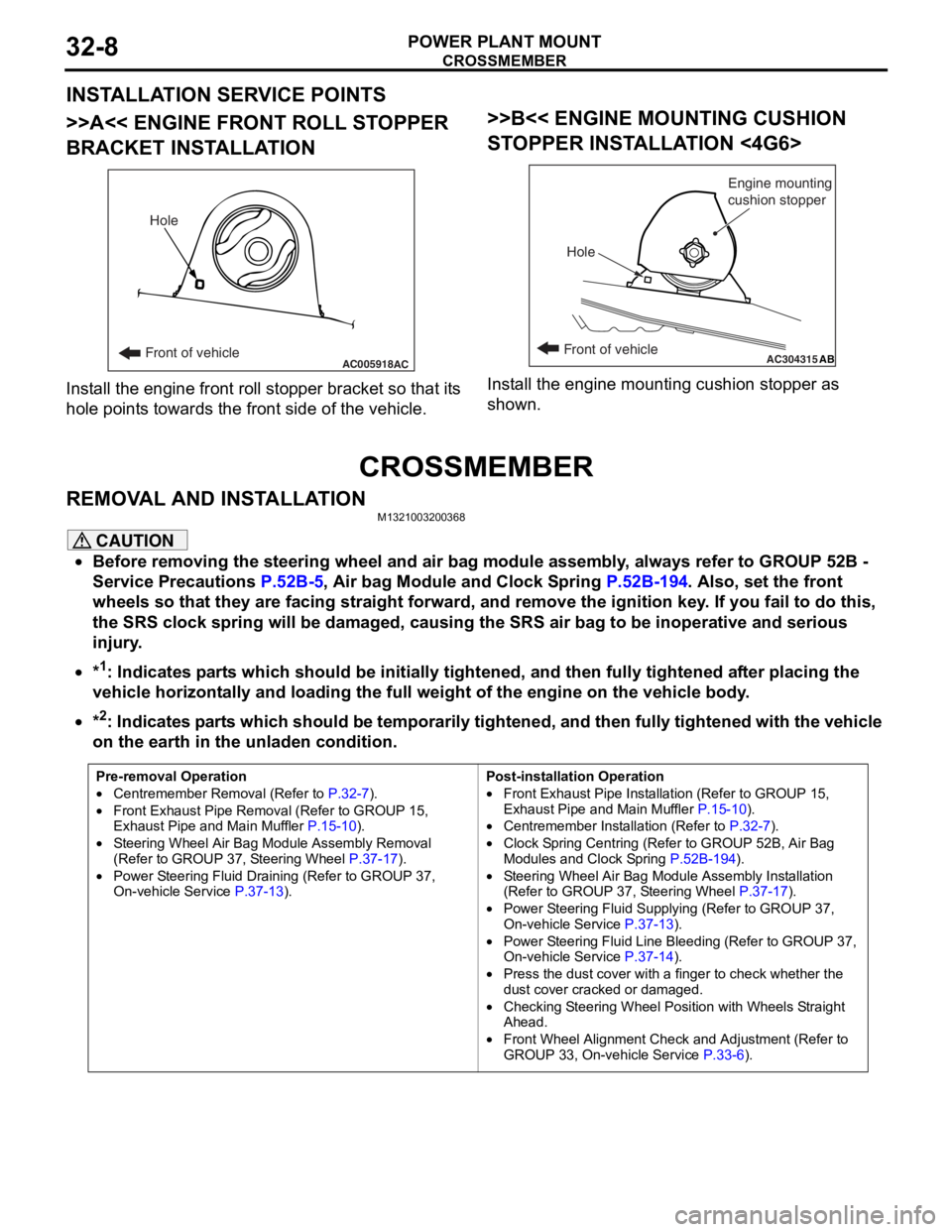
INSTALLATION SERVICE POINTS
>>A<< ENGINE FRONT ROLL STOPPER
BRACKET INSTALLATION
AC005918Front of vehicleHoleAC
Inst
all th e en gine fron t roll stop per b r acket so that it s
hole
point s towards the fro n t side of the vehicle.
>>B<< ENGINE MOUNTING CUSHION
ST
OPPER INST ALLA TION <4G6>
AC304315ABFront of vehicle
Hole Engine mounting
cushion stopper
Inst
all the e ngin e mo untin g cushio n sto pper a s
shown.
CROSSMEMBER
REMOVA L AND INST ALLA TIONM13210032 0036 8
CAUTION
•Before removing the steering wheel and air bag module assembly, always refer to GROUP 52B -
Service Precautions
P.52B-5, Air bag Module and Clock Spring P.52B-194. Also, set the front
wheels so that they are facing straight forward, and remove the ignition key. If you fail to do this,
the SRS clock spring will be damaged, causing the SRS air bag to be inoperative and serious
injury.
•*1: Indicates parts which should be initially tightened, and then fully tightened after placing the
vehicle horizontally and loading the full weight of the engine on the vehicle body.
•
Pre-removal Operation
•Centremember Removal (Refer to P.32-7).
•Front Exhaust Pipe Remova l (Refer to GROUP 15,
Exhaust Pipe and Main Muffler P.15-10).
•Steering Wheel Air Bag Mo dule Assembly Removal
(Refer to GROUP 37, Steering Wheel P.37-17).
•Power Steering Fluid Draining (Refer to GROUP 37,
On-vehicle Service P.37-13).
Post-installation Operation
•Front Exhaust Pipe Installation (Refer to GROUP 15,
Exhaust Pipe and Main Muffler
P.15-10).
•Centremember Installation (Refer to P.32-7).
•Clock Spring Centring (Refer to GROUP 52B, Air Bag
Modules and Clock Spring P.52B-194).
•Steering Wheel Air Bag Module Assembly Installation
(Refer to GROUP 37, Steering Wheel P.37-17).
•Power Steering Fluid Supplying (Refer to GROUP 37,
On-vehicle Service P.37-13).
•Power Steering Fluid Line Bleeding (Refer to GROUP 37,
On-vehicle Service P.37-14).
•Press the dust cover with a finger to check whether the
dust cover cracked or damaged.
•Checking Steering Wheel Position with Wheels Straight
Ahead.
•Front Wheel Alignment Check and Adjustment (Refer to
GROUP 33, On-vehicle Service P.33-6).
*2: Indicates parts which should be temporarily tightened, and then fully tightened with the vehicle
on the earth in the unladen condition.
Page 191 of 800
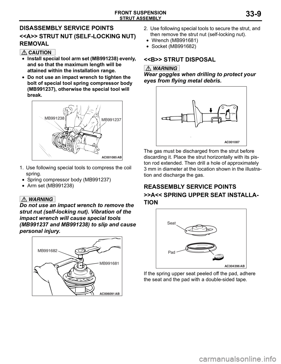
Page 192 of 800
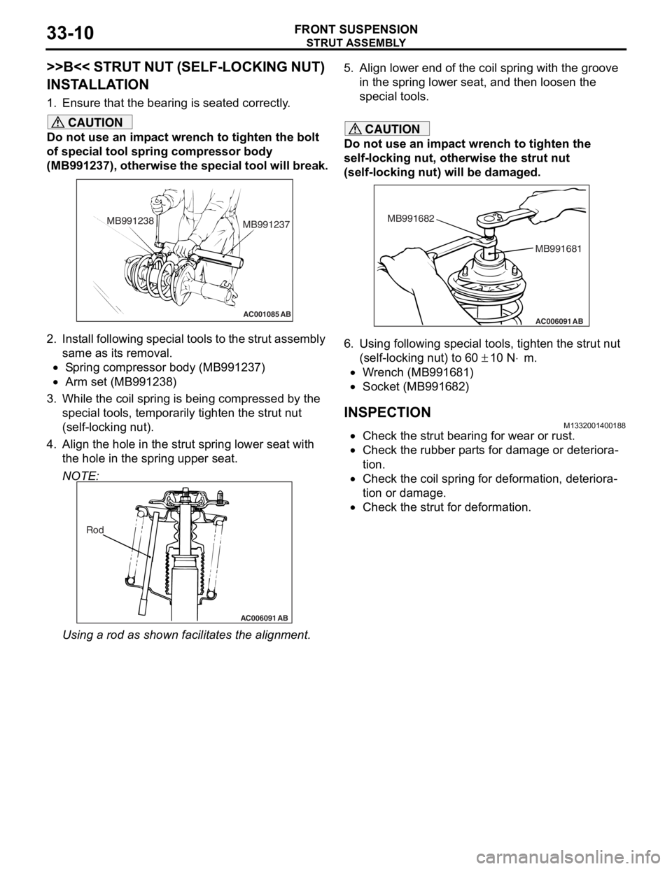
STRUT ASSEMBLY
FRONT SUSPENSION33-10
>>B<< STRUT NUT (SELF-LOCKING NUT)
INSTALLATION
1. Ensure that the bearing is seated correctly.
CAUTION
Do not use an impact wrench to tighten the bolt
of special tool spring compressor body
(MB991237), otherwise the special tool will break.
AC001085 AB
MB991238MB991237
2. Install following special tools to the strut assembly
same as its removal.
•Spring compressor body (MB991237)
•Arm set (MB991238)
3. While the coil spring is being compressed by the
special tools, temporarily tighten the strut nut
(self-locking nut).
4. Align the hole in the strut spring lower seat with the hole in the spring upper seat.
NOTE:
AC006091 AB
Rod
Using a rod as shown fa cilitates the alignment.
5. Align lower end of the coil spring with the groove
in the spring lower seat, and then loosen the
special tools.
CAUTION
Do not use an impact wrench to tighten the
self-locking nut, otherwise the strut nut
(self-locking nut) will be damaged.
AC006091 AB
MB991681
MB991682
6. Using following special tools, tighten the strut nut
(self-locking nut) to 60
± 10 N⋅m.
•Wrench (MB991681)
•Socket (MB991682)
INSPECTIONM1332001400188
•Check the strut bearing for wear or rust.
•Check the rubber parts for damage or deteriora-
tion.
•Check the coil spring for deformation, deteriora-
tion or damage.
•Check the strut for deformation.
Page 196 of 800
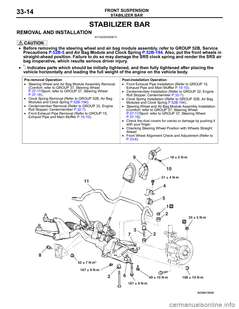
STABILIZER BAR
FRONT SUSPENSION33-14
STABILIZER BAR
REMOVAL AND INSTALLATIONM1332004000673
CAUTION
•Before removing the steering wheel and air bag module assembly, refer to GROUP 52B, Service
Precautions
P.52B-5 and Air Bag Module and Clock Spring P.52B-194. Also, put the front wheels in
straight-ahead position. Failure to do so may damage the SRS clock spring and render the SRS air
bag inoperative, which results serious driver injury.
•
Pre-removal Operation
•Steering Wheel and Air Bag Module Assembly Removal
(Comfort: refer to GROUP 37, Steering Wheel
P.37-17/Sport: refer to GROUP 37, Steering Wheel P.37-18).•Clock Spring Removal (Refer to GROUP 52B, Air Bag
Modules and Clock Spring P.52B-194).
•Centermember Removal (Ref er to GROUP 32, Engine
Roll Stopper, Centermember P.32-7).
•Front Exhaust Pipe Remova l (Refer to GROUP 15,
Exhaust Pipe and Main Muffler P.15-10).
Post-installation Operation
•Front Exhaust Pipe Installation (Refer to GROUP 15,
Exhaust Pipe and Main Muffler P.15-10).•Centermember Installation (Refer to GROUP 32, Engine
Roll Stopper, Centermember P.32-7).
•Clock Spring Installation (Refer to GROUP 52B, Air Bag
Modules and Clock Spring P.52B-194).
•Steering Wheel and Air Bag Module Assembly Installation
(Comfort: refer to GROUP 37, Steering Wheel
P.37-17/Sport: refer to GROUP 37, Steering Wheel P.37-18).•Check the dust covers for cracks or damage by pushing it
with your finger.
•Checking Steering Wheel Position with Wheels Straight
Ahead
•Front Wheel Alignment Check and Adjustment (Refer to P.33-6).
AC006139 AE
49 ± 10 N·m 108 ± 10 N·m
167 ± 9 N·m
167 ± 9 N·m
52 ± 7 N·m* 25 ± 5 N·m
21 ± 4 N·m
18 ± 2 N·m
10
9
4
5 1
2
2
3
7
6
2
11
8
*: Indicates parts which should be initially tightened, and then fully tightened after placing the
vehicle horizontally and loading the full weight of the engine on the vehicle body.