body MITSUBISHI LANCER 2006 User Guide
[x] Cancel search | Manufacturer: MITSUBISHI, Model Year: 2006, Model line: LANCER, Model: MITSUBISHI LANCER 2006Pages: 800, PDF Size: 45.03 MB
Page 56 of 800
INLET MANIFOLD
INTAKE AND EXHAUST15-6
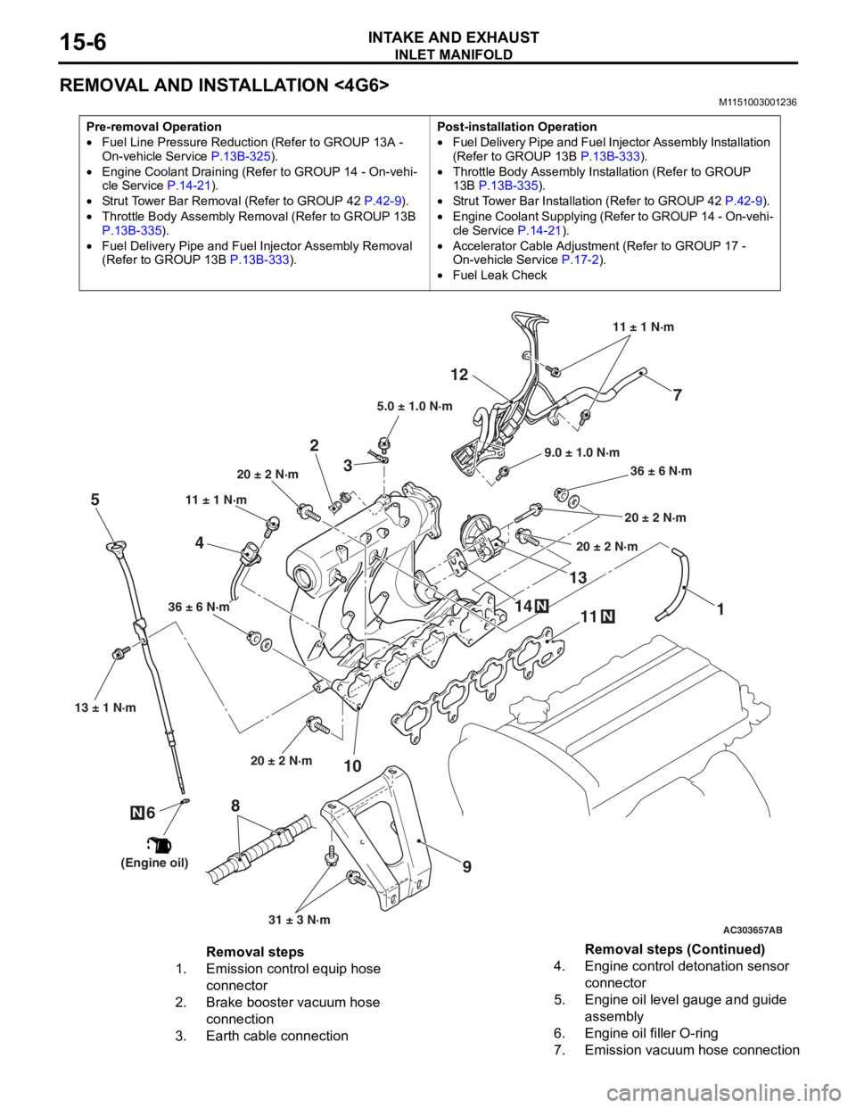
REMOVAL AND INSTALLATION <4G6>
M1151003001236
Pre-removal Operation
•Fuel Line Pressure Reduction (Refer to GROUP 13A -
On-vehicle Service P.13B-325).
•Engine Coolant Draining (Refer to GROUP 14 - On-vehi-cle Service P.14-21).
•Strut Tower Bar Removal (Refer to GROUP 42 P.42-9).
•Throttle Body Assembly Re moval (Refer to GROUP 13B
P.13B-335).
•Fuel Delivery Pipe and Fuel Injector Assembly Removal
(Refer to GROUP 13B
P.13B-333).
Post-installation Operation
•Fuel Delivery Pipe and Fuel Injector Assembly Installation
(Refer to GROUP 13B P.13B-333).
•Throttle Body Assembly Inst allation (Refer to GROUP
13B P.13B-335).
•Strut Tower Bar Installati on (Refer to GROUP 42 P.42-9).
•Engine Coolant Supplying (Refer to GROUP 14 - On-vehi-
cle Service P.14-21).
•Accelerator Cable Adjustment (Refer to GROUP 17 -
On-vehicle Service
P.17-2).
•Fuel Leak Check
AC303657
9.0 ± 1.0 N·m11 ± 1 N·m
20 ± 2 N·m 31 ± 3 N·m
36 ± 6 N·m
20 ± 2 N·m
20 ± 2 N·m
36 ± 6 N·m
20 ± 2 N·m
11
9
10
2
12
N14
13N
AB
5.0 ± 1.0 N·m
3
1
11 ± 1 N·m
4
N
13 ± 1 N·m
5
6
(Engine oil)
7
8
Removal steps
1.Emission control equip hose
connector
2.Brake booster vacuum hose
connection
3.Earth cable connection
4.Engine control detonation sensor
connector
5.Engine oil level gauge and guide
assembly
6.Engine oil filler O-ring
7.Emission vacuum hose connection
Removal steps (Continued)
Page 68 of 800

CHARGING SYSTEM
ENGINE ELECTRICAL16-6
9. Check that the reading on the voltmeter is equal
to the battery voltage.
NOTE: If the voltage is 0 V, the cause is probably
an open circuit in the wire or fusible link between
the alternator "B" terminal and the battery (+) ter
-
minal.
10.Turn the light switch on to turn on headlamps and
then start the engine.
11.Immediately after setting the headlamps to high
beam and turning the heater blower switch to the
high revolution position, increase the engine
speed to 2,500 r/min and read the maximum
current output value displayed on the ammeter.
Limit: 70 % of normal current output
NOTE: .
•For the nominal current output, refer to the
Alternator Specifications.
•Because the current from the battery will soon
drop after the engine is started, the above step
should be carried out as quickly as possible in
order to obtain the maximum current output
value.
•The current output value will depend on the
electrical load and the temperature of the
alternator body.
•If the electrical load is small while testing, the
specified level of current may not be output
even though the alternator is normal. In such
cases, increase the electrical load by leaving
the headlamps turned on for some time to dis
-
charge the battery or by using the lighting sys-
tem in another vehicle, and then test again.
•The specified level of current also may not be
output if the temperature of the alternator body
or the ambient temperature is too high. In such
cases, cool the alternator and then test again.
12.The reading on the ammeter should be above the
limit value. If the reading is below the limit value
and the alternator output wire is normal, remove
the alternator from the engine and check the
alternator.
13.Run the engine at idle after the test.
14.Turn the ignition switch to the "LOCK" (OFF)
position.
15.Remove the tachometer or the M.U.T.-II/III.
16.Disconnect the negative battery cable.
17.Disconnect the ammeter and voltmeter.
18.Connect the negative battery cable.
Page 86 of 800
STARTING SYSTEM
ENGINE ELECTRICAL16-24
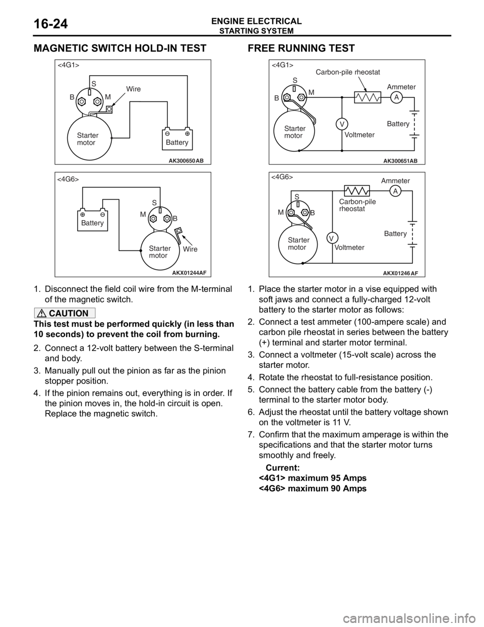
MAGNETIC SWITCH HOLD-IN TEST
AK300650AB
<4G1>S
B MWire
Battery
Starter
motor
AKX01244
<4G6>
SB
M
Battery
Starter
motorWire
AF
1.
Disco nnect the field coil wire f r om th e M-te rmin al
of the magnet ic switch.
CAUTION
This test must be performed quickly (in less than
10 seconds) to prevent the coil from burning.
2. Connect a 12-volt battery between the S-terminal and body.
3. Manually pull out the pinion as far as the pinion stopper position.
4. If the pinion remains out, everything is in order. If
the pinion moves in, the hold-in circuit is open.
Replace the magnetic switch.
FREE RUNNING TEST
AK300651AB
<4G1>
S
A
M
V
B
Carbon-pile rheostat
Battery
Voltmeter Ammeter
Starter
motor
AKX01246
<4G6> S
M B Ammeter
Carbon-pile
rheostat
Battery
Starter
motor Voltmeter
AF
A
V
1. Place the starter motor in a vise equipped with soft jaws and connect a fully-charged 12-volt
battery to the starter motor as follows:
2. Connect a test ammeter (100-ampere scale) and carbon pile rheostat in series between the battery
(+) terminal and starter motor terminal.
3. Connect a voltmeter (15-volt scale) across the starter motor.
4. Rotate the rheostat to full-resistance position.
5. Connect the battery c able from the battery (-)
terminal to the starter motor body.
6. Adjust the rheostat until the battery voltage shown
on the voltmeter is 11 V.
7. Confirm that the maximum amperage is within the specifications and that the starter motor turns
smoothly and freely.
Current:
<4G1> maximum 95 Amps
<4G6> maximum 90 Amps
Page 87 of 800
STARTING SYSTEM
ENGINE ELECTRICAL16-25
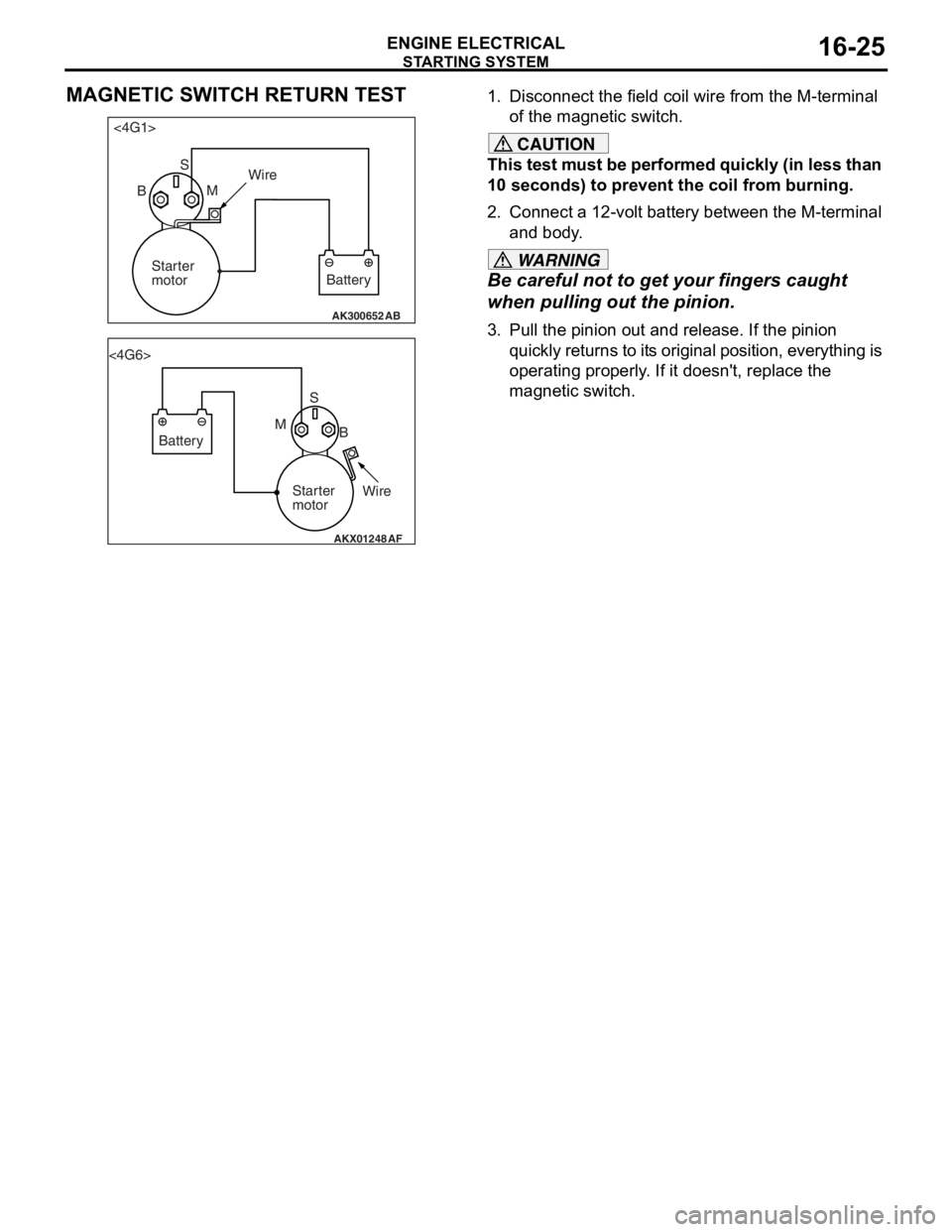
MAGNETIC SWITCH RETURN TEST
AK300652AB
<4G1>S
B MWire
Battery
Starter
motor
AKX01248
<4G6>
SB
M
Battery
Starter
motorWire
AF
1.
Disco nnect the field coil wire f r om th e M-te rmin al
o f the magnet ic switch.
CAUTION
This test must be performed quickly (in less than
10 seconds) to prevent the coil from burning.
2. Connect a 12-volt battery between the M-terminal and body.
WARNING
Be careful not to ge t your fingers caught
when pulling out the pinion.
3. Pull the pinion out and release. If the pinion
quickly returns to its original position, everything is
operating properly. If it doesn't, replace the
magnetic switch.
Page 91 of 800
AK202734
STARTING SYSTEM
ENGINE ELECTRICAL16-29
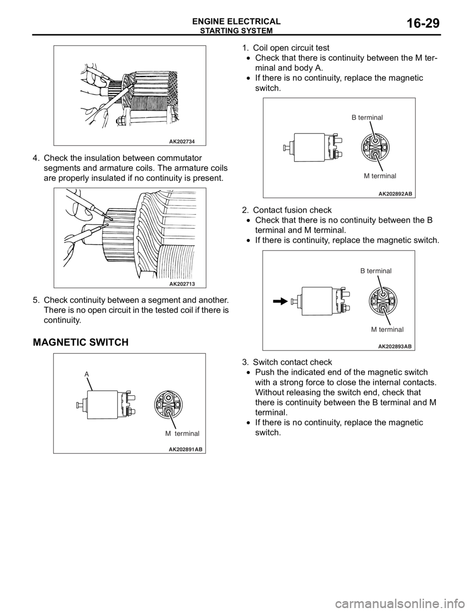
4. Check t he in sulation between commut ator
segment s an d arma ture coils. Th e armature coils
are prope rly insu lated if no con t inuity is pre s ent .
AK202713
5. Check continuit y bet ween a segment and another .
Th ere is n o ope n circui t in th e t e s t e d c o il if t h e r e is
continuity .
MA GNETIC SW ITCH
AK202891
A
M terminal
AB
1.Coil ope n circuit test
•Check that there is continuity be twe en the M te r-
minal and body A.
•
AK202892
M terminal
B terminal
AB
If th
ere is no continuit y , replace t he ma gnetic
sw
itc h .
2.Cont act fusion check
•Check that there is no co ntinu i ty between the B
termina
l and M te rmin al.
•
AK202893
M terminal
B terminal
AB
If th
ere is co ntinu i ty , re place the magn etic switch.
3.Switch cont act check
•Push the indicated end o f the magne tic switch
with
a stro ng force to close th e inte rnal cont act s .
Without re
leasing the switch end, check tha t
the
r e is con t inuity b e tween th e B terminal and M
termina
l .
•If there is no continuit y , replace t he ma gnetic
sw
itc h .
Page 109 of 800
ENGINE CONTROL
ENGINE AND EMISSION CONTROL17-3
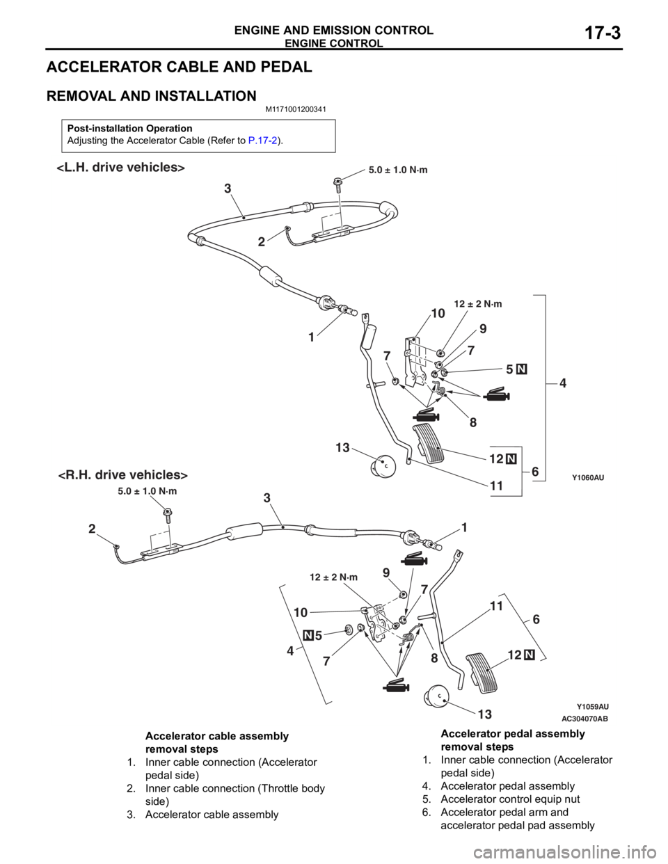
ACCELERATOR CABLE AND PEDAL
REMOVAL AND INSTALLATION
M1171001200341
Post-installation Operation
Adjusting the Accelerator Cable (Refer to P.17-2).
Y1059AU
Y1060AU
AC304070
N
4
5 7 8
10
11
N12
13
AB
1
2 3
5.0 ± 1.0 N·m
6
12 ± 2 N·m9
7
1
2
3
5.0 ± 1.0 N·m
N
4
5
7
8
10
11
N12
13
6
12 ± 2 N·m
9
7
Accelerator cable assembly
removal steps
1.Inner cable connection (Accelerator
pedal side)
2.Inner cable connection (Throttle body
side)
3.Accelerator cable assembly
Accelerator pedal assembly
removal steps
1.Inner cable connection (Accelerator
pedal side)
4.Accelerator pedal assembly
5.Accelerator control equip nut
6.Accelerator pedal arm and
accelerator pedal pad assembly
Page 113 of 800
EMISSION CONTROL
ENGINE AND EMISSION CONTROL17-7
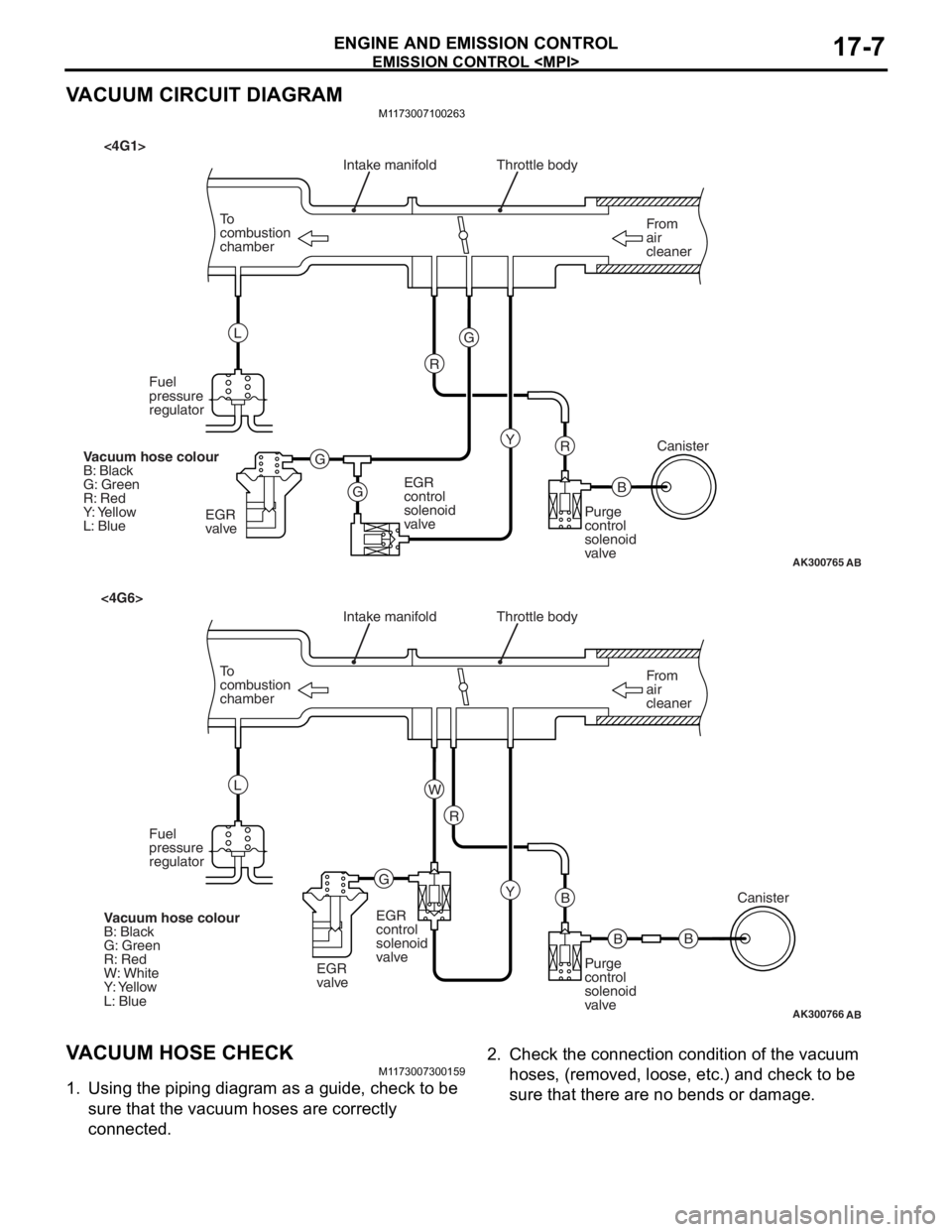
VACUUM CIRCUIT DIAGRAM
M1173007100263
AK300765
From
air
cleaner
To
combustion
chamber Throttle body
B
R
AB
Intake manifold
Y
G
G G R
L
Fuel
pressure
regulator
EGR
valve EGR
control
solenoid
valve
Purge
control
solenoid
valveCanister
Vacuum hose colour
B: Black
G: Green
R: Red
Y: Yellow
L: Blue
<4G1>
AK300766
From
air
cleaner
To
combustion
chamber Throttle body
B
B
AB
Intake manifold
Y
R
G W
L
Fuel
pressure
regulator
EGR
valveEGR
control
solenoid
valve
Purge
control
solenoid
valveCanister
Vacuum hose colour
B: Black
G: Green
R: Red
W: White
Y: Yellow
L: Blue
<4G6>
B
V ACUUM HOSE CHECK
M1 173 0073 0015 9
1.Using th e pip i ng d i agra m as a gu ide, check to be
sure th at the vacuum h o ses are correctly
connected.
2. Check t he co nnection cond itio n of th e vacuum
ho s e s, (re mo v e d, l o os e , et c . ) an d c h e c k t o b e
sure th at there are no bends or da mage .
Page 116 of 800
EMISSION CONTROL
ENGINE AND EMISSION CONTROL17-10
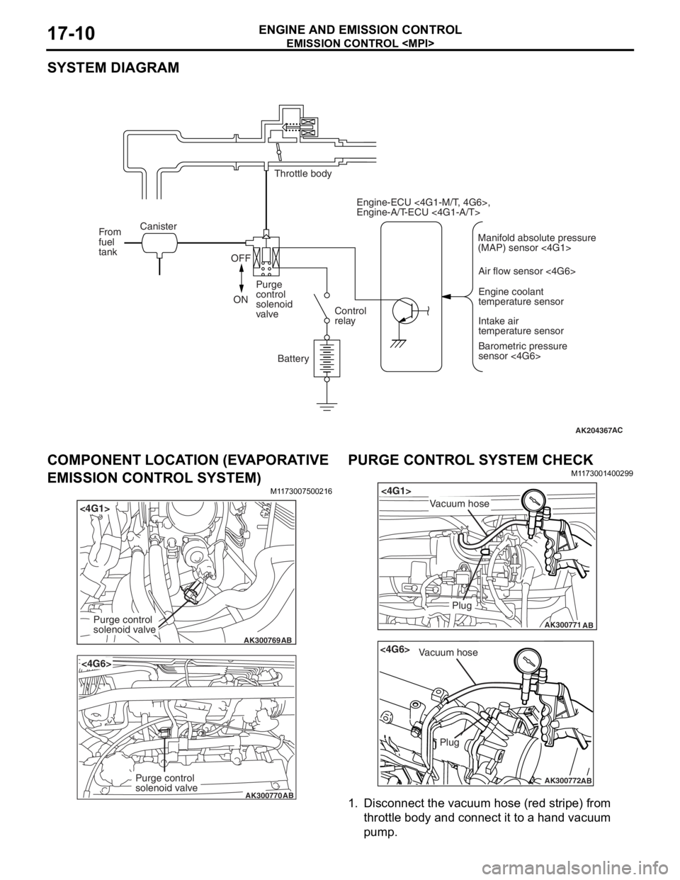
SYSTEM DIAGRAM
AK204367AC
Throttle body
Canister
From
fuel
tank
OFF
ON Purge
control
solenoid
valve
Control
relay
Battery Engine-ECU <4G1-M/T, 4G6>,
Engine-A/T-ECU <4G1-A/T>
Air flow sensor <4G6>Engine coolant
temperature sensor
Intake air
temperature sensor
Barometric pressure
sensor <4G6>
Manifold absolute pressure
(MAP) sensor <4G1>
COMPONENT LOCA
TION (EV A PORA TIVE
EMISSION CONTROL SYSTEM)
M1173 0075 0021 6
AK300769
<4G1>
AB
Purge control
solenoid valve
AK300770
<4G6>
AB
Purge control
solenoid valve
PURGE CONTROL SYSTEM CHECK
M1173 0014 0029 9
AK300771
<4G1>
AB
Plug
Vacuum hose
AK300772
<4G6>
AB
Plug
Vacuum hose
1.Disco nnect the vacu um h o se (re d str i pe) fro m
th rottle body and conne ct it to a h and vacu um
pu m p .
Page 117 of 800
EMISSION CONTROL
ENGINE AND EMISSION CONTROL17-11
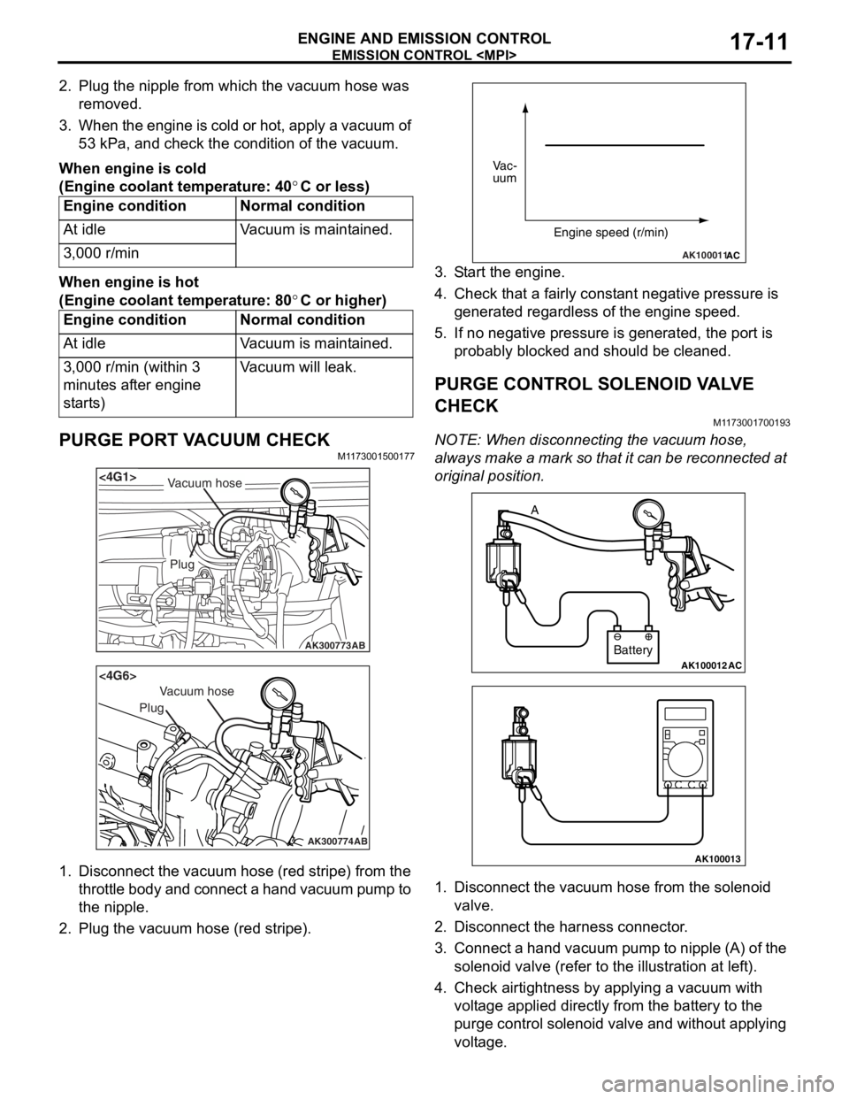
2. Plug the nipple from which the vacuum hose was removed.
3. When the engine is cold or hot, apply a vacuum of 53 kPa, and check the condition of the vacuum.
When engine is cold
(Engine coolant temperature: 40°C or less)
Engine conditionNormal condition
At idleVacuum is maintained.
3,000 r/min
When engine is hot
(Engine coolant temperature: 80°C or higher)
Engine conditionNormal condition
At idleVacuum is maintained.
3,000 r/min (within 3
minutes after engine
starts)Vacuum will leak.
PURGE PORT VACUUM CHECKM1173001500177
AK300773
<4G1>
AB
Plug
Vacuum hose
AK300774
<4G6>
AB
Plug
Vacuum hose
1.Disco nnect th e vacuum ho se (red st ripe) from the
throttle body and connect a hand vacuum pump to
th e nip p le.
2.Plu g the vacuum hose (red stripe).
AK100011AC
Vac-
uum
Engine speed (r/min)
3.S t art the engine.
4.Check t hat a f a irly co nst ant n egative p r essure is
g enerate d regard l ess of the en gine spee d.
5.If no neg ative pressur e is genera t ed, th e port is
p r obably blocked an d sh ould be cleane d.
PURGE CONTROL SOLENOID VA L V E
CHECK
M1173 0017 0019 3
NOTE: Whe n discon nect i ng th e va cuum hose,
always make a mark so th at it can be reconnected at
original p o sition.
AK100012AC
Battery
A
AK100013
1.
Disco nnect the vacu um h o se f r om th e solenoid
valve.
2.Disco nnect the ha rness connector .
3.Con nect a ha nd vacu um pump to nipp le (A) of the
solen o id valve (ref e r to th e ill ust r ation at le f t ).
4.Check a i rtig htness b y app lying a vacuum with
volt age applied d i rectly from t he batt e ry to the
p u rge con t rol so leno id valve an d without app lying
volt age .
Page 136 of 800
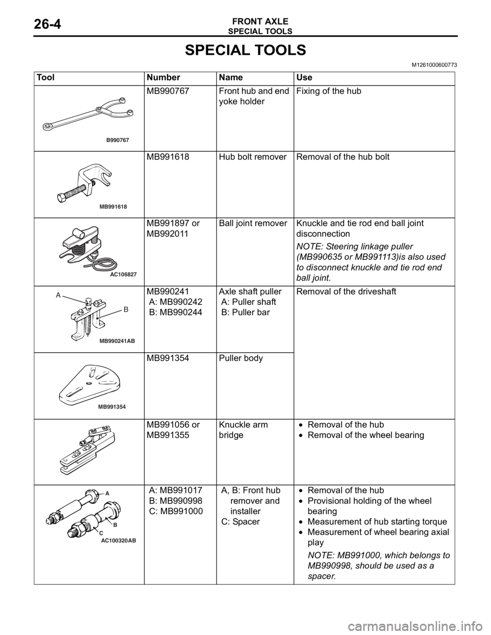
SPECIAL TOOLS
FRONT AXLE26-4
SPECIAL TOOLS
M1261000600773
ToolNumberNameUse
B990767
MB990767Fr o n t hu b a n d en d
yoke holderFixing of the h u b
MB991618
MB991618Hub bolt remo verRemoval of the h ub bolt
AC106827
MB991897 or
MB992
01 1Ball j o int remo verKnuckle and tie rod e nd ball joint
discon
nection
NOTE: St eering linkage pu lle r
(MB990 635 or MB991 1 13)is also u s ed
to disconnect kn uckle an d tie rod en d
bal
l j
o
int.
MB990241AB
A BMB990241
A: MB9902 42
B: MB990244
Axle shaft pu ller
A: Puller shaf t
B: Puller bar
Rem o va l of t h e dri v es h a f t
MB991354
MB991354Pulle r body
MB991 056 or
MB991
355Knuckle a r m
bridg
e•Removal of the hu b
•Removal of the whee l bea ring
AC100320 ABA
B
C
A: MB9910 17
B: MB990998
C: MB99100 0
A, B: Fr ont hu b
remover and
ins t all e r
C: Sp acer
•Removal of the hu b
•Prov ision a l ho ldin g of th e wheel
b
earin g
•Measurement of hub st a r ting t o rque
•Measurement of wh eel b earin g axial
pl
a y
NOTE: MB9 91000, which b e lon g s to
MB9909 98, should be used a s a
sp
acer
.