cooling MITSUBISHI LANCER 2006 Owner's Guide
[x] Cancel search | Manufacturer: MITSUBISHI, Model Year: 2006, Model line: LANCER, Model: MITSUBISHI LANCER 2006Pages: 800, PDF Size: 45.03 MB
Page 45 of 800
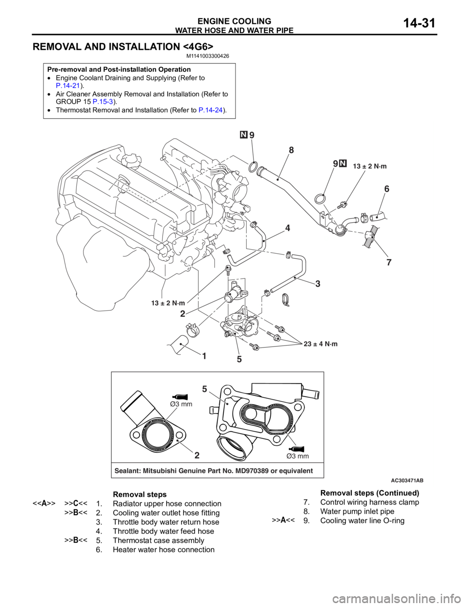
WATER HOSE AND WATER PIPE
ENGINE COOLING14-31
REMOVAL AND INSTALLATION <4G6>
M1141003300426
Pre-removal and Post-installation Operation
鈥ngine Coolant Draining and Supplying (Refer to P.14-21).
鈥ir Cleaner Assembly Removal and Installation (Refer to
GROUP 15 P.15-3).
鈥hermostat Removal and Installation (Refer to P.14-24).
AC303471
1
2
3
4
5 6
7
8
9
9
13 卤 2 N路m
23 卤 4 N路m
13 卤 2 N路m
N
N
AB
2
Sealant: Mitsubishi Genuine Part No. MD970389 or equivalent
脴3 mm
脴3 mm
5
Removal steps
<>>>C<<1.Radiator upper hose connection
>>B<<2.Cooling water outlet hose fitting
3.Throttle body water return hose
4.Throttle body water feed hose
>>B<<5.Thermostat case assembly
6.Heater water hose connection
7.Control wiring harness clamp
8.Water pump inlet pipe
>>A<<9.Cooling water line O-ring
Removal steps (Continued)
Page 46 of 800
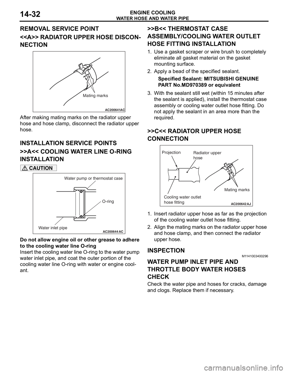
Page 47 of 800
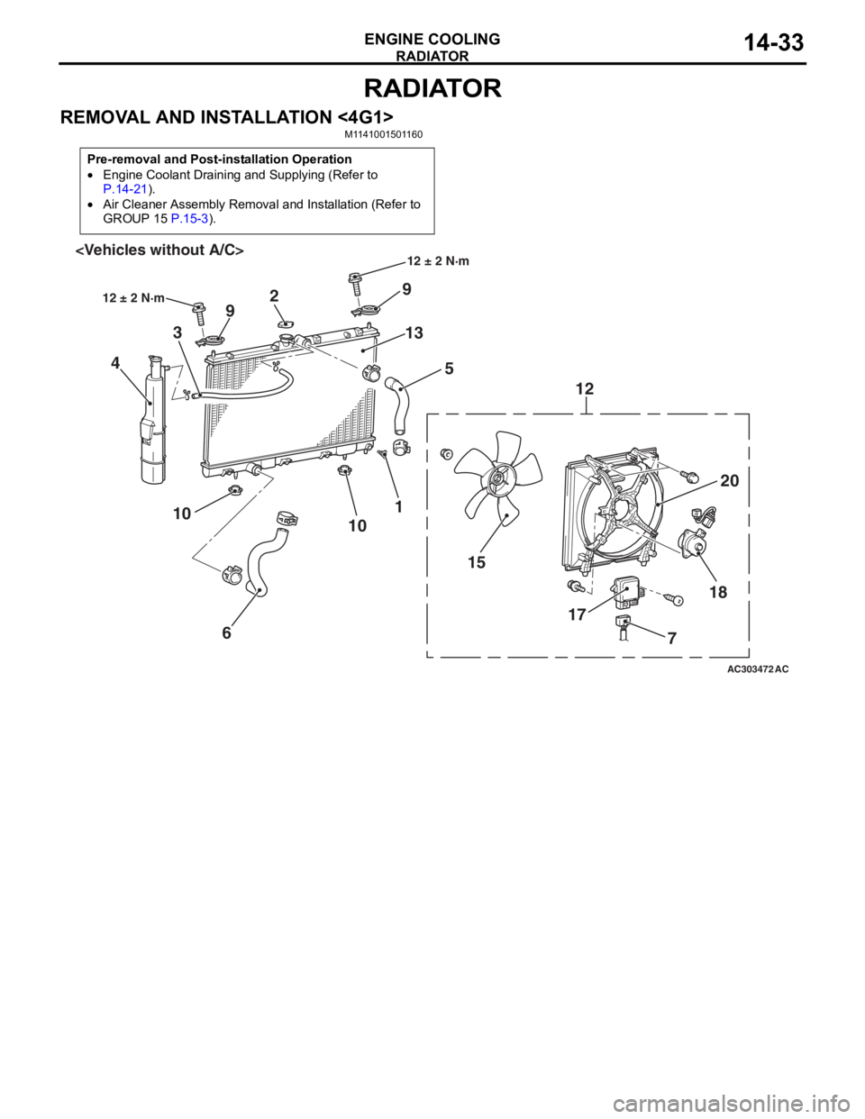
RADIATOR
ENGINE COOLING14-33
RADIATOR
REMOVAL AND INSTALLATION <4G1>M1141001501160
Pre-removal and Post-installation Operation
鈥ngine Coolant Draining and Supplying (Refer to
P.14-21).
鈥ir Cleaner Assembly Removal and Installation (Refer to
GROUP 15
P.15-3).
AC303472
18
17
15 20
12
9
13 5
2
9
3
4
1
10
6
10
AC
12 卤 2 N路m
12 卤 2 N路m
7
Page 48 of 800
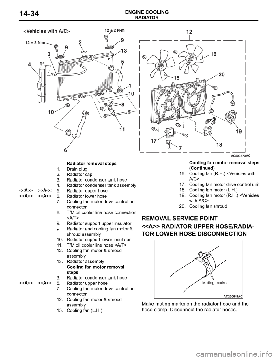
AC303473
18
17 15
20
12
9
13
5
2
9
3
4
1
10
6
10
12 卤 2 N路m
AC
12 卤 2 N路m
16
19
8
11
7
Radiator removal steps
1.Drain plug
2.Radiator cap
3.Radiator condenser tank hose
4.Radiator condenser tank assembly
<>>>A<<5.Radiator upper hose
<>>>A<<6.Radiator lower hose
7.Cooling fan motor drive control unit
connector
8.T/M oil cooler line hose connection
9.Radiator support upper insulator
鈥adiator and cooling fan motor &
shroud assembly
10.Radiator support lower insulator
11 .T/M oil cooler line hose
12.Cooling fan motor & shroud
assembly
13.Radiator assembly
Cooling fan motor removal
steps
3.Radiator condenser tank hose
<>>>A<<5.Radiator upper hose
7.Cooling fan motor drive control unit
connector
12.Cooling fan motor & shroud
assembly
15.Cooling fan (L.H.)
16.Cooling fan (R.H.)
17.Cooling fan motor drive control unit
18.Cooling fan motor (L.H.)
19.Cooling fan motor (R.H.)
20.Cooling fan shroud
RADIA T OR
ENGINE COOLING14-34
REMOV A L SER VICE POINT
<> RADIAT OR UPPER HOSE/RADIA-
TO R LOW E R HOSE DISCONNECTION
AC200641AC
Mating marks
Make mating marks on the rad i ator hose and th e
hose
cla m p. Disconnect the ra diat or hoses.
Cooling fan motor removal steps
(Continued)
Page 49 of 800
RADIATOR
ENGINE COOLING14-35
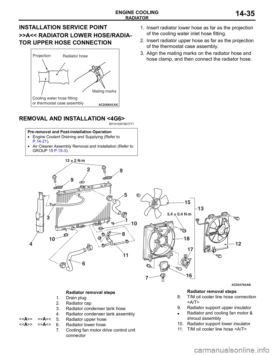
INSTALLATION SERVICE POINT
>>A<< RADIATOR LOWER HOSE/RADIA-
TOR UPPER HOSE CONNECTION
AC200642
Mating marks
Projection
Cooling water hose fitting
or thermostat case assembly
AK
Radiator hose
1.In sert ra diato r lower h o se as fa r as th e projection
o f the cooling wate r inlet hose fit t ing.
2.In sert radia t or up per h o se as far a s t he pro j ection
o f the th ermost at ca se asse mbly .
3.Align th e ma ting marks on the rad i ator hose and
h o se clamp, an d then conn ect the radiator h o se.
REMOVA L AND INST ALLA TION <4G6>
M11 4100 1501 17 1
Pre-removal and Post-installation Operation
鈥ngine Coolant Draining and Supplying (Refer to
P.14-21).
鈥ir Cleaner Assembly Removal and Installation (Refer to
GROUP 15
P.15-3).
AC504783
1
12 卤 2 N路m
10
2
3
4
5
6
7
8
9
9
10
11 13
15
18
16
17
12
AB
5.4 卤 0.4 N路m
Radiator removal steps
1.Drain plug
2.Radiator cap
3.Radiator condenser tank hose
4.Radiator condenser tank assembly
<>>>A<<5.Radiator upper hose
<>>>A<<6.Radiator lower hose
7.Cooling fan motor drive control unit
connector
8.T/M oil cooler line hose connection
9.Radiator support upper insulator
鈥adiator and cooling fan motor &
shroud assembly
10.Radiator support lower insulator
11 .T/M oil cooler line hose
Radiator removal steps
Page 50 of 800
RADIATOR
ENGINE COOLING14-36
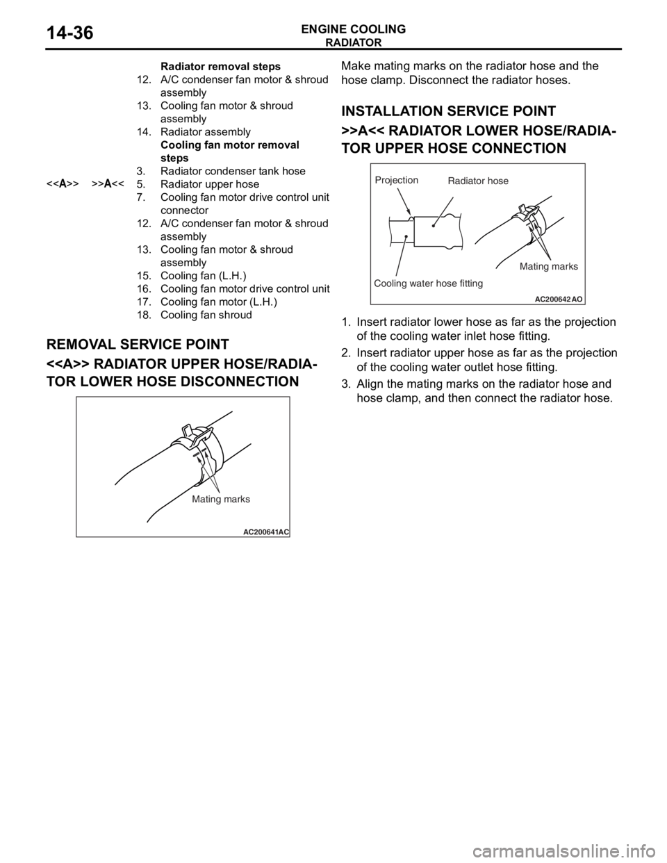
REMOVAL SERVICE POINT
<> RADIATOR UPPER HOSE/RADIA-
TOR LOWER HOSE DISCONNECTION
AC200641AC
Mating marks
Make mating marks on the rad i ator hose and th e
hose
cla m p. Disconnect the ra diat or hoses.
INSTALLA T ION SER VICE POINT
>>A<< RADIAT OR LOW E R HOSE/RADIA-
TO R UPPER HOSE CONNECTION
AC200642
Mating marks
Projection
Cooling water hose fitting
AO
Radiator hose
1.In sert ra diato r lower h o se as fa r as th e projection
o f the cooling wate r inlet hose fit t ing.
2.In sert radia t or up per h o se as far a s t he pro j ection
o f the cooling wate r outle t hose fitt ing.
3.Align th e ma ting marks on the rad i ator hose and
h o se clamp, an d then conn ect the radiator h o se.
12.A/C con den se r fan mo to r & sh ro ud
assembly
13.Coo ling fan mo to r & sh ro ud
assembly
14.Rad i ator a s sem b ly
Cooling fan mo tor r e mova l
st
ep s
3.Radi ator con den ser t a nk h o se
<>>>A<<5.Radi ator u ppe r ho se
7.Cooling fan mo to r dr ive contr o l unit
con
nector
12.A/C con den se r fan mo to r & sh ro ud
assembly
13.Coo ling fan mo to r & sh ro ud
assembly
15.Coo ling fan ( L .H.)
16.Coo ling fan mo to r dr ive contro l unit
17.Coo ling fan mo to r ( L .H.)
18.Coo ling fan shr o u d
Radiator re mova l st ep s
Page 392 of 800
ECU
COMPONENT LOCATIONS70-2
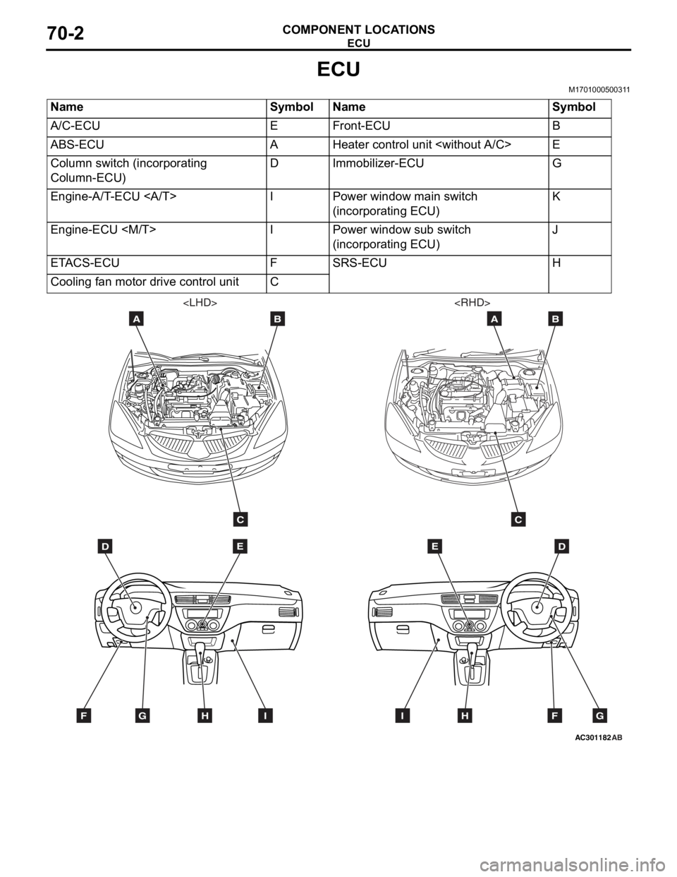
ECU
M1701000500311
NameSymbolNameSymbol
A/C-ECUEFront-ECUB
ABS-ECUAHeater control unit
Column switch (incorporating
Column-ECU)DImmobilizer-ECUG
Engine-A/T-ECU IPower window main switch
(incorporating ECU)K
Engine-ECU
(incorporating ECU)J
ETACS-ECUFSRS-ECUH
Cooling fan motor drive control unitC
AC301182
DE
AB
C
FGHI
AB
DE
AB
C
FGHI
Page 393 of 800
AC304537
JK*
AE
ECU
COMPONENT LOCA TIONS70-3
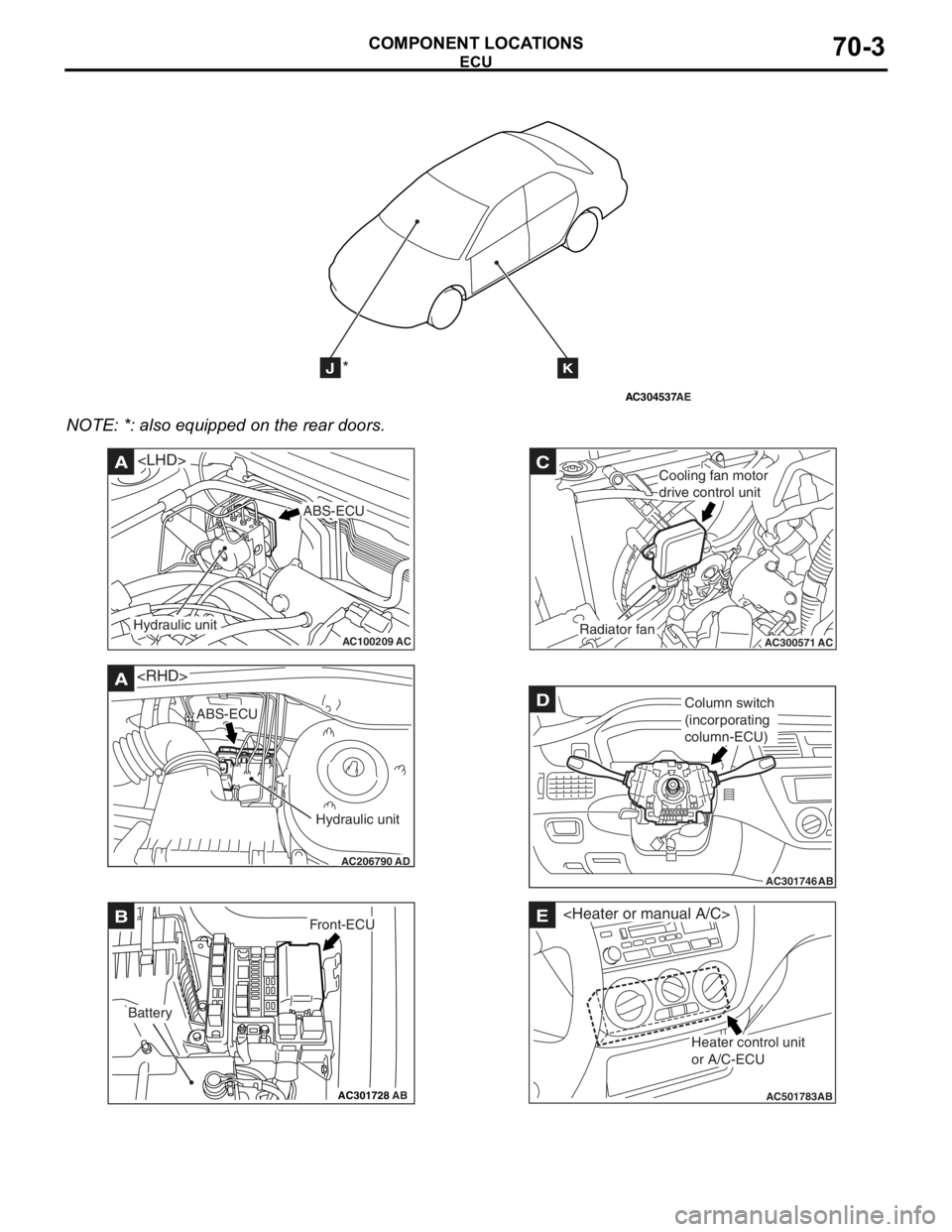
NOTE: *: also eq uipp ed on the rear doors.
AC100209AC
A
ABS-ECU
Hydraulic unit
AC206790
A
AD
ABS-ECU
Hydraulic unit
AC301728AB
BFront-ECU
Battery
AC300571
C
ACRadiator fan
Cooling fan motor
drive control unit
AC301746
DColumn switch
(incorporating
column-ECU)
AB
AC501783AB
E
Heater control unit
or A/C-ECU
Page 417 of 800
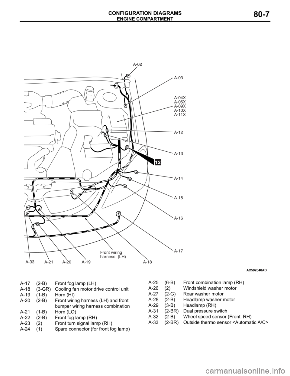
AC502048AB
A-02A-03
A-04X
A-05X
A-09X
A-10X
A-11X
A-12
A-13
A-14
A-15
A-16
A-17
A-18
A-19
A-20
A-21 Front wiring
harness
(LH)
12
A-33
A-17(2-B)Front fog lamp (LH)
A-18(3-GR)Cooling fan motor drive control unit
A-19(1-B)Horn (HI)
A-20(2-B)Front wiring harness (LH) and front
bumper wiring harness combination
A-21(1-B)Horn (LO)
A-22(2-B)Front fog lamp (RH)
A-23(2)Front turn signal lamp (RH)
A-24(1)Spare connector (for front fog lamp)
A-25(6-B)Front combination lamp (RH)
A-26(2)Windshield washer motor
A-27(2-G)Rear washer motor
A-28(2-B)Headlamp washer motor
A-29(3-B)Headlamp (RH)
A-31(2-BR)Dual pressure switch
A-32(2-B)Wheel speed sensor (Front: RH)
A-33(2-BR)Outside thermo sensor
ENGINE COMP AR TMEN T
CONF IGURA TION D I A G RA MS80-7
Page 419 of 800
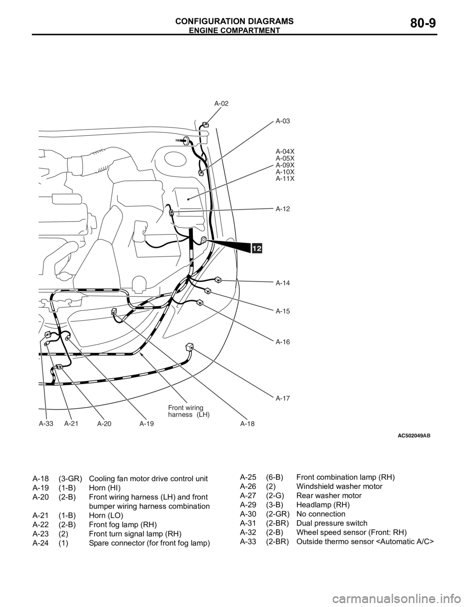
AC502049
A-33
AB
A-02A-03
A-04X
A-05X
A-09X
A-10X
A-11X
A-12
A-14
A-15
A-16
A-17
A-18
A-19
A-20
A-21 Front wiring
harness
(LH)
12
A-18(3-GR)Cooling fan motor drive control unit
A-19(1-B)Horn (HI)
A-20(2-B)Front wiring harness (LH) and front
bumper wiring harness combination
A-21(1-B)Horn (LO)
A-22(2-B)Front fog lamp (RH)
A-23(2)Front turn signal lamp (RH)
A-24(1)Spare connector (for front fog lamp)
A-25(6-B)Front combination lamp (RH)
A-26(2)Windshield washer motor
A-27(2-G)Rear washer motor
A-29(3-B)Headlamp (RH)
A-30(2-GR)No connection
A-31(2-BR)Dual pressure switch
A-32(2-B)Wheel speed sensor (Front: RH)
A-33(2-BR)Outside thermo sensor
ENGINE COMP AR TMEN T
CONF IGURA TION D I A G RA MS80-9